FDU
1
2
3
4
5
6
7
8
9
10
11
12
13
14
15
1
2
3
4
5
6
7
8
9
10
11
12
13
14
15
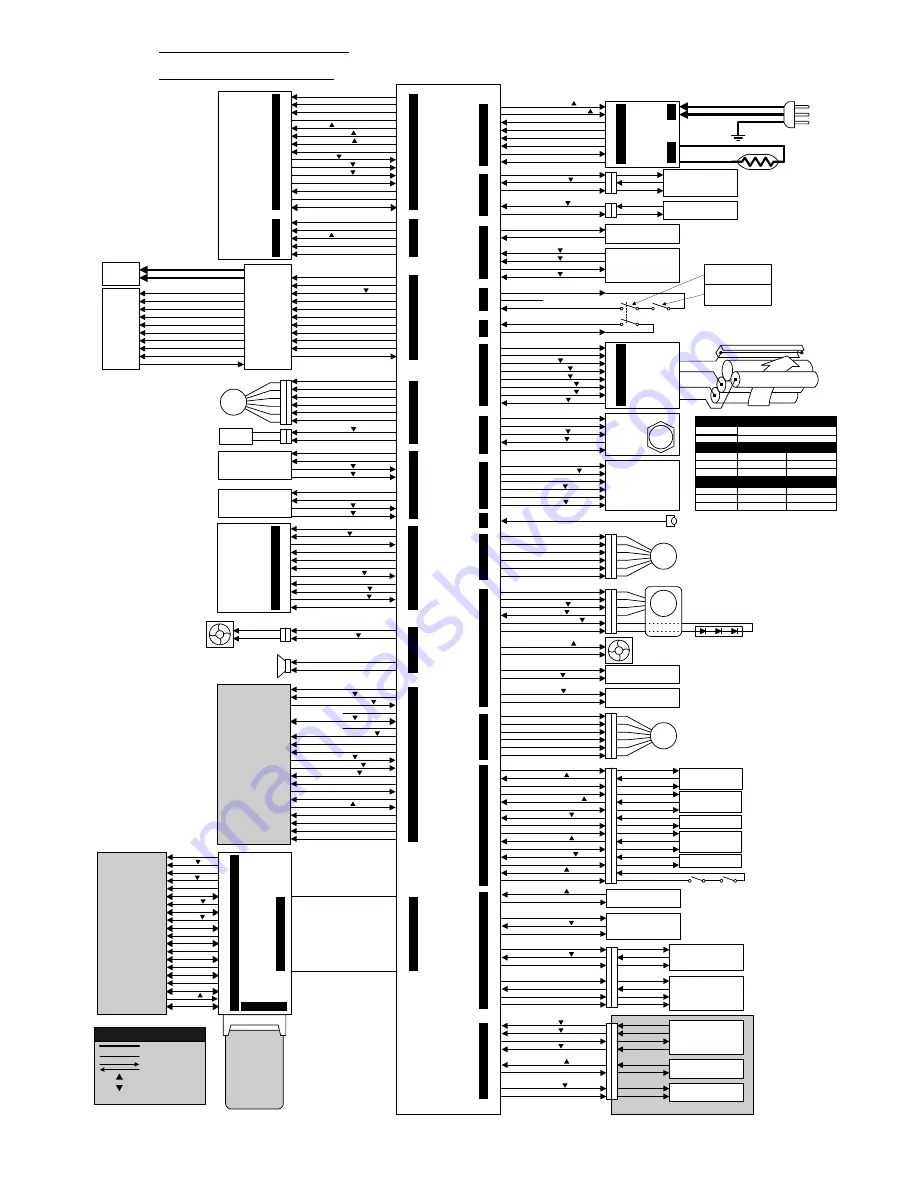
Point-to-Point Diagram
Point-to-Point Diagram
Model: LSO (MV310)
Model: LSO (MV310)
Issued on: May 22nd, 1995
Revision 1.0
Subject to change
Transfer Bias (T)
Toner Application Bias (B1)/ Development Bias
(B2)
OFF/OFF
Bias 0 = L
Bias 0 = H
Bias 1 = L
Bias 1 = H
-700V/ - 400V
- 50V/ +250V
OFF/-400V
OFF
Bias 0 = L
Bias 0 = H
Bias 1 = L
Bias 1 = H
+5
µµ
A
- 1000V
OFF
Charge Bias (C)
Charge = H
Charge = L
- 305
µµ
A
OFF
AC Line
DC Line
Signal Direction
Active High
Active Low
Voltage
Symbol Table
[ ]
Tx
Motor
Paper End Sensor
(Standard Cassette)
Bypass Feed Sensor
Registration Sensor
Toner End Sensor
Not used
Toner End Sensor Output
+5V
COM1
Paper Present [
5]
+5V
COM1
+5V
Paper Present [
5]
COM1
COM1
Paper End [
5]
1
2
3
4
5
6
7
8
9
10
11
12
CN7
Scanner
Motor
A
BB
COM34
B
AB
COM12
1
2
3
4
5
6
CN17
PI1
Laser Syncronization Signal (Optical Fibre)
+24V
+24VD
Not used
+5V
+5VLD
Top Cover Interlock
Switch
Front Cover Interlock
Switch
1
2
CN11
1
2
3
CN10
1
2
3
4
5
6
CN63
Paper
Feed
Motor
A
BB
+24VMM
B
AB
+24VMM
CN61
1
2
3
4
5
6
7
8
9
10
11
12
13
14
15
COM1
COM1
Cover Open [ 5V]
COM1
B4 Original Present [
5V]
COM1
Original Present [
5V]
+5V
COM1
Original Present [
5V]
+5V
Scanner at Home Position [
5V]
COM1
+5V
Cover Open [ 5V]
Platen Cover
Switch
Scanner HP
Sensor
Document Sensor
Scan Line Sensor
B4 Width Sensor
ADF Cover
Switch
ADF Release
Switch
Document Width
Sensor
+5V
COM1
5SIZE 2 [
5]
5SIZE 3 [
5]
1
2
3
4
5
6
7
8
Document Length
Sensor
+5V
COM1
5SIZE 0 [
5]
5SIZE 1 [
5]
CN64
CN62
A
BB
COM34
B
AB
COM12
1
2
3
4
5
6
7
8
Stamp
+24VD
Stamp ON [
24]
RS232C Interface
(Optional)
FCE
1
2
3
4
5
6
7
8
9
10
11
12
13
14
15
16
17
18
19
20
CN1
CN3
CN2
CN1
100 pins
IC Card
(Optional)
68 pins
A0
D7
1DEIT2 [
5 ]
D6
A3
D5
A2
D4
A1
D3
COM1
D2
5EXCS0 [
5]
D1
5RSRES [
5]
D0
+5V
5RD [
5]
COM1
5WR [
5]
1
2
3
4
5
6
7
8
9
10
11
12
13
14
15
16
17
18
19
20
CN3
Printer Interface
(Optional)
Controller Ready [
5]
+24V
COM3
COM3
+5V
Interrupt [
5]
Serial Data (Status)
Serial Data (Command)
Serial Clock
Printer Ready [
5]
COM1
Print Start [
5]
Vertical Synchronization Signal
Horizontal Synchronization Signal
Line Synchronization Signal [
5]
Not used
Print Data [
5]
Not used
Printer Interface Installed [
5]
PIF Reset [
5]
CN18
COM1
Speaker Output
Monitor Speaker
Ozone Fan Motor
+24VM
Fan Motor ON [
24]
1
2
3
4
OPU
CN1
1
2
3
4
5
6
7
8
9
10
11
1
2
3
4
5
6
7
8
9
10
11
CN23
Reset [
5]
COM1
Document Sensor ON [
5 ]
Energy Saver LED ON [
5 ]
+5VE
Energy Saver Key [
5 ]
COM1
Serial Data
Serial Clock
Serial Data
+5V
NCU
CN1
1
2
3
4
5
CN2
1
2
3
4
5
6
7
8
9
10
11
12
13
14
15
CN4
+24V
HOOK1 [
5]
EXTDI [
5] (US only)
COM1
OHDISW [
5]
CMLSW [
5]
DOSW [
5] (US - Not used)
Not used
RSEL (US - Not used)
COM3
TRXD (Tx/Rx Signal)
Not used
COM2
EXRING
HOOK0 [
5]
1
2
3
4
5
CN5
CSEL1 (US - Not used)
+5VEE (US - Not used)
+5VE (US - Not used)
GSSW [
5] (US - Not used)
CSEL0 (US - Not used)
+24V
+24V
COM3
Power to the Fusing Lamp ON [
5]
Fusing Lamp ON [
5]
COM3
+24VM
COM3
ACL
ACN
GND
ACN
ACL
PSU
1
2
3
4
5
6
7
8
CN4
CN2
CN1
1
2
3
4
5
6
7
8
CN12
Fusing Exit Sensor
Fusing Exit Cover Sensor
COM1
Cover Open [
5]
+5V
Paper Present [
5]
COM1
1
2
3
4
5
CN13
Fusing Thermistor
Paper Size Sensor
(Standard Cassette)
+5V
COM1
CAS2 [
5]
CAS1 [
5]
CAS0 [
5]
Thermistor Output
1
2
3
4
5
6
CN25
Charge
Transfer
Toner
Application
Development
+24V P.P.
Charger Leak [
24]
Development Bias 1 [
24]
Development Bias 0 [
24]
Transfer Bias 1 [
24]
Transfer Bias 0 [
24]
Charge [
24]
COM3
Power
Pack
1
2
3
4
5
6
7
8
CN1
C
T
B1
B2
1
2
3
4
5
6
7
8
CN21
LDDR
+5VLD
LD Enable [
5]
COM1
Print Data [
5]
COM1
5APC Sampling Hold [
5]
1
2
3
4
5
6
CN26
CN15
Paper Feed Clutch
+24VD
Clutch On [
24]
Mechanical Counter
(Optional)
Count-up [
24]
+24VD
Fusing Fan Motor
COM3
Fan Motor Enable [
24]
1
2
3
4
5
6
7
8
9
10
11
12
Quenching Lamp
+24VM
Quenching Lamp Enable [
24]
+24VD
Motor Lock [
5]
Motor Enable [
24]
COM3
Main
Motor
1
2
3
4
5
6
7
8
100 Sheet Cassette (Optional)
Paper Feed Clutch
CAS4 [
5]
CAS6 [
5]
COM1
CAS5 [
5]
+24VM
Clutch ON [
24]
COM1
Paper End [
5]
Paper End Sensor
Paper Size Sensor
CN20
Xe Lamp
AC
AC
COM3
+24VM
Analog Video Signal
COM1
+5VV
-5V
+5VV
Line Synchronization Signal
COM1
Clock
Contact
Image
Sensor
CN60
1
2
3
4
5
6
7
8
9
10
11
COM3
+24VM
Analog Video Signal
COM1
+5VV
-5V
+5VV
Line Synchronization Signal
COM1
Clock
Scanner Lamp ON [
5]
Xe Lamp
Driver
Polygonal
Mirror
Motor
+24VM
Motor Clock
Motor Lock [
5]
Motor Enable [
24]
COM3
1
2
3
4
5
CN14

