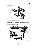
5.7.3. FDU and FCE
Harness Connections from the FDU
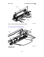
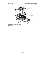
[A]
[B]
H521R045.wmf
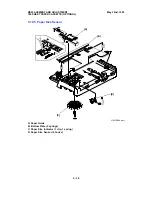
Note: The NCU should be removed first.
A: FDU (2 screws)
B: FCE (2 screws)
After installing the new FCE, transfer the RAM data from the old FCE using service
function 12 (refer to section 4.1.22).
FDU
CN3
CN4
CN61
CN104
CN7
CN5
CN12
CN1
CN41
CN40
CN51
CN13
CN63
CN15
CN62
CN17
CN20
CN18
CN21
CN60
CN50
CN64
CN23
CN26
CN10
CN25
CN14
Sensors
- Paper Exit
- Fusing Exit
Cover
NCU
Printer I/F
(Optional)
Sensors
- Paper End
- Bypass Feed
- Registration
- Toner End
Paper Feed
Motor
Main Motor
Quenching Lamp
Fan Motor
Mech. Counter
Paper Feed CL
Tx Motor
Stamp
Scanner
Motor
Not Used
Not Used
Polygonal
Mirror Motor
Not Used
Paper Size Sensor
Thermistor
PSU
100 Sheet
Cassette
(Optional)
Ozone Fan
Speaker
Power Pack
Contact
Image Sensor
Not Used
LDDR
Fusing Unit
Cover
Interlock
Switch (+5V)
Doc. Width
Sensor
Doc. Length
Sensor
OPU
Video Signal Test
Pins
FCE
Platen Cover Sw.
Scanner HP
Sensor
ADF Sensors
Not
Used
CN11
Fusing Unit Cover
Interlock Switch (+24V)
H521R545.wmf
May 22nd, 1995
REPLACEMENT AND ADJUSTMENT
PCBs
5 - 25

