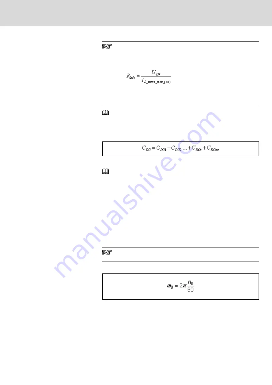
Charging resistance of HCS03 converters
In HCS03.1E-W0070…0150 converters, the DC bus is charged
via integrated resistors for charging current limitation, and in
HCS03.1E-W0210 converters, it is charged via a thyristor circuit:
The charging ability is limited by the properties of the integrated
resistor; its resistance value clearly rises with increasing thermal
load.
For the data of the inrush current I
L_trans_max_on
and the mains voltage U
LN
,
see Project Planning Manual "Rexroth IndraDrive Supply Units and Power
Sections" → Chapter of the respective device → "Technical Data" → "Basic
Data" → table "Data for Mains Voltage Supply".
Resulting DC Bus Capacitance
Effective DC bus capacitance of all devices at common DC bus:
C
DC
Capacitance in DC bus
Fig.15-51:
DC Bus Capacitance
For the data of the capacitance in DC bus C
DC
, see Project Planning
Manual "Rexroth IndraDrive Supply Units and Power Sections" → Chapter of
the respective device → "Technical Data" → "Basic Data" → table "Data of
Power Section - DC bus".
15.4.2
Calculating Speed Characteristic and Braking Time With DC Bus
Short Circuit (ZKS)
Components equipped with the ZKS function (e.g HLB01) short-circuit the DC
bus via the braking resistor when the DC bus short circuit (ZKS) is active. At
synchronous motors with permanent magnet excitation, the short circuit cau‐
ses speed-dependent braking torque.
The braking torque and the braking time can be estimated with the following
formulas.
The calculation formulas below can only be applied to rotary mo‐
tors for which, in addition, the relation L
d
/ L
q
must be approx. 1.
Basic Formula 1
ω
0
[Initial angular velocity motor] = s
-1
n
0
[Motor speed at beginning of ZKS] = min
-1
Fig.15-52:
Initial Angular Velocity
DOK-INDRV*-SYSTEM*****-PR06-EN-P
Rexroth IndraDrive Drive Systems with HMV01/02 HMS01/02, HMD01, HCS02/03
Bosch Rexroth AG
277/309
Calculations


