Correction Factor for Bundling of Lines (Installation Methods B2 and E) and
Circuits (Installation Method B1
1)
)
Number of lines
1
2
3
4
5
Correction factor according to
EN 60204‑1:2006, table D.2
1
1,25
1,43
1,54
1,67
Correction factor according to
NFPA 79:2007, table 12.5.5(b)
1
1,25
1)
Three single cores (L1, L2, L3) for mains supply of a device are to be
considered as one circuit.
Tab.15-7:
Correction Factor for Bundling of Lines and Circuits in Accordance
with EN 60204-1:2006 and NFPA 79:2007
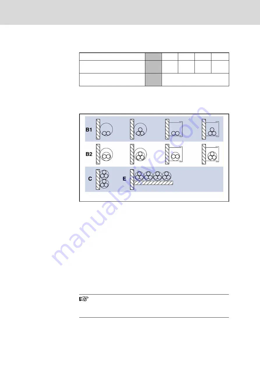
B1
Conductor in installation pipes and in installation channels to be
opened
B2
Cables or lines in installation pipes and in installation channels to be
opened
C
Cables or lines on walls
E
Cables or lines on open cable trays.
Fig.15-40:
Installation methods (compare IEC 60364-5-52; VDE0298-7; EN
60204-1)
15.3.6
Determining the Leakage Capacitance
The capacitances which generate so-called leakage currents against ground
at the outputs of inverters are regarded as leakage capacitance C
ab
. The de‐
cisive values for the total value C
ab_g
of the leakage capacitance are:
●
Capacitances of output filters
●
Capacitances of power cables (capacitance per unit length against
shield and ground wire)
●
Capacitances of motors (winding capacitance against housing)
The capacitance per unit length of the hybrid cable of Rexroth
IndraDrive Mi is insignificant for determining the leakage capaci‐
tance, because the hybrid cable is at the DC bus and not at the
output of the inverter.
Bosch Rexroth AG
DOK-INDRV*-SYSTEM*****-PR06-EN-P
Rexroth IndraDrive Drive Systems with HMV01/02 HMS01/02, HMD01, HCS02/03
272/309
Calculations


