


1-6
System overview
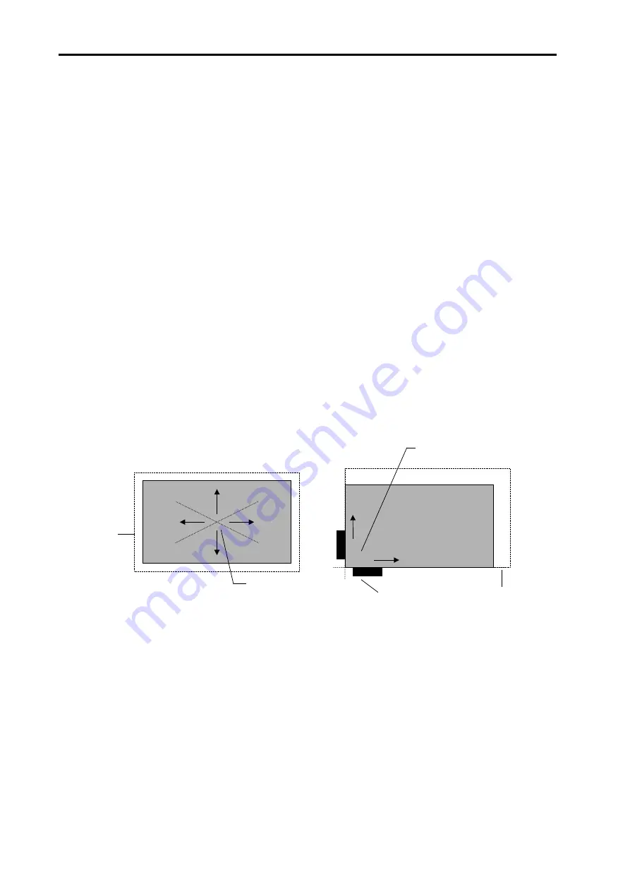
Workpiece expansion concept
The size of a workpiece is proportional to its CTE and the ambient temperature. One of
the major sources of error in large parts can be ‘feature misplacement’, which can result
from thermal expansion or contraction of the part.
Consider two matching workpieces – one made at 30 °C (86 °F) and one made at 20 °C
(68 °F). If these parts are machined without workpiece expansion compensation applied,
they will not be the same size when brought together at the same temperature (the part
made at the higher temperature will be smaller than the one made at the lower
temperature).
By constantly monitoring the workpiece temperature, the RCU10 can use its CTE to
calculate the expansion that has occurred relative to a nominal reference temperature of
20 °C (68 °F). This process ensures that parts machined in a poorly controlled
environment will be as accurate and consistent as parts machined in an environment
maintained at 20 °C (68 °F). That is to say, no matter what temperature the part is
machined at, it will be the correct size when measured at 20 °C (68 °F).
Expansion is a greater problem in large workpieces because the amount of expansion is
proportional to the distance from the reference point. For example, at a point 40 m
(
≈
130 ft) from the reference point on an aluminium workpiece at 30 °C (86 °F), the error
will be 8 mm (5/16 in).
New
‘expanded’
size
Reference point,
centre of the
workpiece
Anchor
point
Expanded
size
Expansion is forced in
these directions, away
from the anchor point
Figure 1.4 – Workpiece expansion
Workpiece compensation reference point
It is up to each user to establish a reference point suitable for their specific workpiece and
application. Some experimentation may need to be carried out in order to determine how
each fixture or workpiece behaves and thus the best way to apply compensation.
The process of defining a reference point can be complex and depends on many factors.
It is up to the user to decide on the best jigging and anchoring options for the workpiece.
Summary of Contents for RCU10
Page 1: ...Installation and user s guide M 9904 1122 09 A RCU10 quadrature compensation unit...
Page 11: ...viii Contents This page is intentionally left blank...
Page 23: ...1 12 System overview This page is intentionally left blank...
Page 39: ...2 16 System design...
Page 49: ...3 6 Kit configuration and part identification This page is intentionally left blank...
Page 67: ...4 18 System installation This page is intentionally left blank...
Page 91: ...A 6 RCU10 system specifications This page is intentionally left blank...
Page 147: ...E 8 Commissioning tests This page is intentionally left blank...
Page 175: ...F 28 Extended capability This page is intentionally left blank...
Page 189: ...G 14 Reference This page is intentionally left blank...
Page 193: ...H 4 Test records This page is intentionally left blank Cut here Cut here...
Page 195: ...H 6 Test records This page is intentionally left blank Cut here Cut here...