


Extended capability
F-7
F.1.5
Parameter table selection
A number of ‘parameter tables’ may be available for use during operation. The purpose of
these is to allow the easy selection of a number of common options/operations.
The parameters which may be selected are shown below:
Dead path for laser encoders or reference offset from scale expansion origin
Workpiece temperature sensor serial number
Workpiece expansion coefficient
Workpiece origin offset
Workpiece origin type
The use of these switchable parameters allows such options as:
Multiple machine home positions.
Changing to an alternative machining zone.
Use of multiple workpiece material sensors (for multiple machine zones or other
reasons).
Changing of the material type (e.g. aluminium/steel)
The values for these parameters may be pre-configured at
System Configurator
level as
detailed in sections 4.2.4 and F.1.7.1, and then selected during operation by the machine
control or a simple switch.
The number of parameter tables available depends on how the system configurator has
programmed the RCU10s. A maximum of four parameter sets may be selected by use of
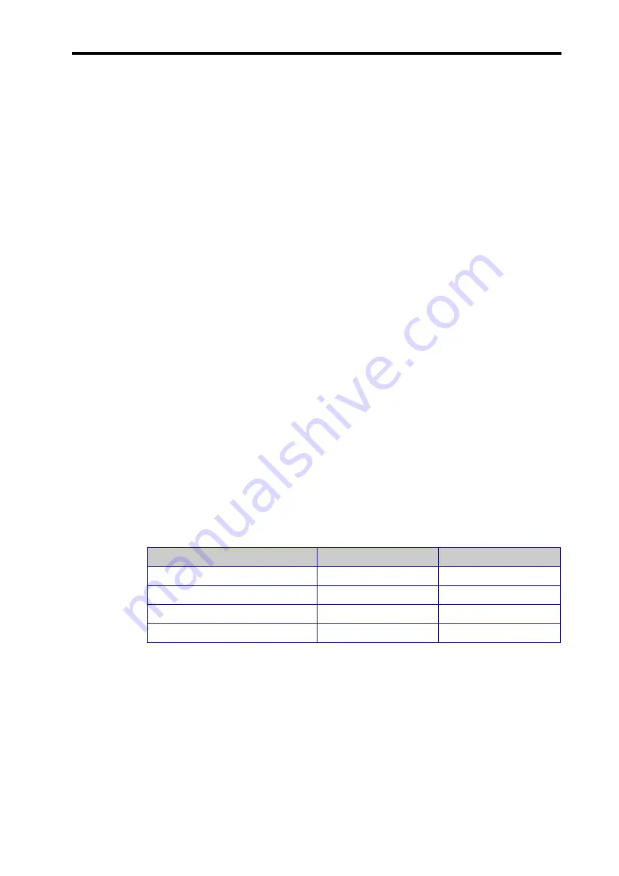
two hardware lines. The selection control is shown in the table below:
Table F.2 – Parameter table selection
Select parameter table
PT select 1
PT select 2
1
HIGH
HIGH
2
LOW
HIGH
3
HIGH
LOW
4
LOW
LOW
(NOTE:
If single parameter table operation is selected, there is not a requirement to
connect to the parameter table select lines.)
The procedure for use should be as follows:
1. Stop the machine/part program.
2. Change the selected parameter table (by use of the control lines).
3. Re-home the machine or axis. Once this is complete, the new parameter set will be
used and displayed in the software. This can be confirmed by looking at the RCU CS
status display screen to see which parameter table is shown as active.
Summary of Contents for RCU10
Page 1: ...Installation and user s guide M 9904 1122 09 A RCU10 quadrature compensation unit...
Page 11: ...viii Contents This page is intentionally left blank...
Page 23: ...1 12 System overview This page is intentionally left blank...
Page 39: ...2 16 System design...
Page 49: ...3 6 Kit configuration and part identification This page is intentionally left blank...
Page 67: ...4 18 System installation This page is intentionally left blank...
Page 91: ...A 6 RCU10 system specifications This page is intentionally left blank...
Page 147: ...E 8 Commissioning tests This page is intentionally left blank...
Page 175: ...F 28 Extended capability This page is intentionally left blank...
Page 189: ...G 14 Reference This page is intentionally left blank...
Page 193: ...H 4 Test records This page is intentionally left blank Cut here Cut here...
Page 195: ...H 6 Test records This page is intentionally left blank Cut here Cut here...