Renishaw RCU10 Installation And User Manual Download Page 139

D-22


Compensation system status information and diagnostics


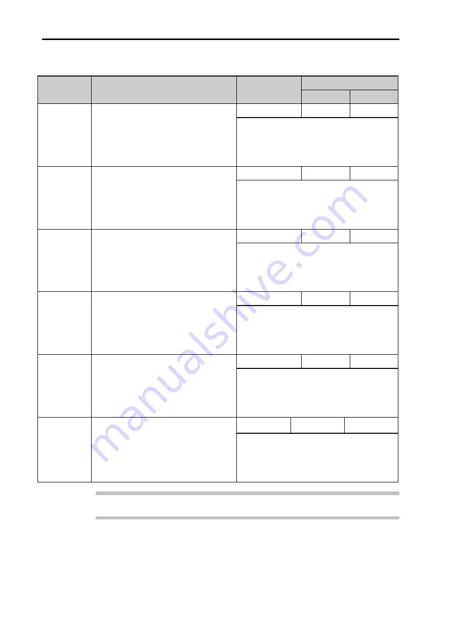
Table D.17 – Axis diagnostics (Sensors tab) 

Error 

Description 

Configuration 

mode 

Compensation mode 

Advanced 

Simple 

Pressure 
Sensor 
Failure 

Allocated pressure sensor has failed. 

WARNING 

SUSPEND 

ERROR 

Check sensor connections. 

Check 

Sensor

 screen for errors. 

Check individual sensor errors. 

Assert 

Reset

 line on Auxiliary I/O connector 

(Error condition only). 

Air Temp 
Sensor 
Failure 

Allocated air temperature sensor has 
failed. 

WARNING 

SUSPEND 

ERROR 

Check sensor connections. 

Check 

Sensor

 screen for errors. 

Check individual sensor errors. 

Assert Reset line on Auxiliary I/O connector 

(Error condition only). 

Workpiece 
Sensor 
Failure 

Allocated material temperature sensor 
has failed. 

WARNING 

SUSPEND 

ERROR 

Check sensor connections. 

Check 

Sensor 

screen for errors. 

Check individual sensor errors. 

Assert 

Reset

 line on Auxiliary I/O connector 

(Error condition only). 

Structure 
Sensor 
Failure 

Allocated material temperature sensor 
has failed. 

WARNING 

SUSPEND 

ERROR 

Check sensor connections. 

Check 

Sensor

 screen for errors. 

Check individual sensor errors. 

Assert 

Reset

 line on Auxiliary I/O connector 

(Error condition only). 

Encoder 
Sensor 
Failure 

Allocated material temperature sensor 
has failed.  

WARNING 

SUSPEND 

ERROR 

Check sensor connections. 

Check 

Sensor

 screen for errors. 

Check individual sensor errors. 

Assert 

Reset

 line on Auxiliary I/O connector 

(Error condition only). 

System 
Sensor 
Failure 

Sensor connected to but not used by 
RCU unit under interrogation has failed. 

WARNING 

WARNING 

WARNING 

Check sensor connections. 

Check 

Sensor

 screen for errors. 

Check individual sensor errors. 

Assert 

Reset

 line on Auxiliary I/O connector 

(Error condition only). 

Note:

 If mode is simple, any rate of change errors are treated as a warning. 

Summary of Contents for RCU10

Page 1: ...Installation and user s guide M 9904 1122 09 A RCU10 quadrature compensation unit...

Page 2: ...y measures that can be included in machine design However it is the sole responsibilty of the OEM system integrator to specify and integrate measures suitable for the application Symbol definition The...

Page 3: ...general household waste Please dispose of the used batteries at a designated collection point This will prevent potential negative effects on the environment and human health which could otherwise ari...

Page 4: ...put see item 3 below If the controller is not capable of detecting open circuit position feedback signals this option must not be enabled 2 The axis must include physical limit switches which when tri...

Page 5: ...axes should be monitored If the difference in their positions exceeds an expected limit then axis motion must be stopped Note In the case of measures 6 9 the limits need to be selected carefully depe...

Page 6: ...3 1 Connector positions 2 5 2 3 2 Connector functions 2 6 J1 24 V dc power 2 6 J2 Controller output 2 6 J3 Encoder input 2 6 J4 Reference switch port 2 7 J7 Auxiliary I O 2 8 J8 PC port 2 9 2 4 Veloci...

Page 7: ...rror testing 5 2 5 2 2 RCU10 error testing 5 3 5 2 3 Testing environment sensors 5 5 5 2 4 Auxiliary I O connector input functions 5 6 5 2 5 Reference mark connector function 5 8 5 2 6 Encoder conside...

Page 8: ...1 Connector pinout B 11 B 6 2 Wiring requirements B 11 B 7 PC port J8 B 13 B 7 1 Connector pinout B 13 B 7 2 Wiring requirements B 13 B 8 Fastlink port B 14 B 9 Sensors J5 J6 B 14 B 9 1 Connector pino...

Page 9: ...2 F 1 2 Extended system status monitoring F 2 F 1 2 1 Extended status monitoring F 2 F 1 3 Axis referencing with extended error lines F 4 F 1 4 Controlling workpiece compensation from motion control s...

Page 10: ...tion of compensation terms G 6 G 2 Air refraction compensation G 9 G 3 Worked example laser compensation G 11 G 3 1 Direction sense setting G 11 G 3 2 Laser dead path LO G 12 G 3 3 Workpiece thermal e...

Page 11: ...viii Contents This page is intentionally left blank...

Page 12: ...ctor 1 4 1 3 2 Air refractive index compensation 1 4 1 3 3 Encoder thermal expansion compensation 1 5 1 3 4 Workpiece thermal expansion compensation 1 5 1 3 5 Structure thermal compensation 1 7 1 4 Op...

Page 13: ...network of sensors and uses advanced digital signal processing to perform real time compensation on the position feedback signals The RCU10 can provide Refractive index compensation for laser encoder...

Page 14: ...to the motion controller The corrected feedback signals are provided to the motion controller in either RS422 digital A quad B or analogue Sin Cos 1 Vpp formats with a nominal accuracy of 1 ppm refra...

Page 15: ...ls can be found in Appendix G 1 3 1 Scale factor The RCU10 is capable of performing a fixed scale factor correction to convert the intrinsic encoder resolution into a more useable value e g 633 nm 1 m...

Page 16: ...for this effect by measuring the temperature of the scale and applying the relevant positional correction This will significantly improve system accuracy when subjected to temperature variation To uti...

Page 17: ...ts machined in an environment maintained at 20 C 68 F That is to say no matter what temperature the part is machined at it will be the correct size when measured at 20 C 68 F Expansion is a greater pr...

Page 18: ...la to convert from ppm C to ppm F ppm C multiplied by 5 9 ppm F e g 20 ppm C x 5 9 11 11 ppm F 1 3 5 Structure thermal compensation An additional source of positioning error may be the thermal distort...

Page 19: ...ging of the material type e g aluminium steel 1 4 2 Compensation buffering When the RCU10 is in this mode it will continue to monitor the encoder input and perform the relevant quadrature scaling Howe...

Page 20: ...buted to other RCU10s in the network via a high speed serial link Compensation unit part number RCU10 XX XX Similar to the RCU10 PX XX however this assembly does not contain a pressure sensor Note tha...

Page 21: ...to meet the requirements of the application Communication with the RCU10 units is established through an RS232 or RS485 serial link in some instances this may necessitate the use of a USB to RS232 co...

Page 22: ...nstallation process detailed information has been placed within the appendices Reference to these appendices is made where appropriate Figure 1 5 Installation flow diagram System design Section 2 Defi...

Page 23: ...1 12 System overview This page is intentionally left blank...

Page 24: ...Controller output 2 6 J3 Encoder input 2 6 J4 Reference switch port 2 7 J7 Auxiliary I O 2 8 J8 PC port 2 9 2 4 Velocity resolution bandwidth considerations 2 9 2 4 1 Encoder input frequency 2 10 2 4...

Page 25: ...digital quadrature in differential RS422 format or analogue Sine Cosine quadrature in 1 Vpp format is capable of recognising an error condition by one of the following methods RS422 differential erro...

Page 26: ...0 sensors are factory programmed with an address that is the same as the serial number of the sensor engraved on the sensor body Each sensor port can supply power to a maximum of four sensors which me...

Page 27: ...wn in Figure 2 3 making a maximum of eight sensors per RCU10 There is a limit of 32 sensors per multi axis system Additionally of these 32 sensors only 24 may be distributed Distributed sensors are th...

Page 28: ...to Appendix B CAUTION Do not connect anything other than Renishaw environmental sensors to the sensor ports 2 3 1 Connector positions Figure 2 4 Front panel layout Figure 2 5 Top panel layout Not curr...

Page 29: ...analogue incremental sine cosine format 1 Vpp differential sine and cosine line driver outputs using the configuration software The output resolution of the RCU10 system may be selected from a number...

Page 30: ...input can accept a range of actuator types that have solid state high side or low side 5 V logic signal or mechanical switch output formats The reference process is triggered by the current s rising e...

Page 31: ...V or 24 V Connect to 5 V 1 or 24 V 11 as required Note This must also be selected to match the RCU10 configuration 5 Seek reference I Enables search for reference mark input LOW 15 Reset I Resets the...

Page 32: ...m Renishaw Alternatively custom cables may be made by the user connector kits are available Please see Appendix B for connector pinouts and standard cable specifications Notes New PCs are increasingly...

Page 33: ...ast 25 greater than the encoder output quadrature rate 2 4 2 Output frequency Determine the RCU10 output controller input resolution Calculate the maximum output frequency as follows Output frequency...

Page 34: ...oder input resolution nm RCU10 output resolution sinusoid period m 20 25 40 50 100 316 5 00 m s 158 3 164 m s 3 164 m s 3 164 m s 79 1 1 582 m s 1 582 m s 1 582 m s 1 582 m s 39 6 0 791 m s 0 791 m s...

Page 35: ...f the reference switch To overcome this the RCU10 includes a circuit that re phases the position signals so that the reference mark output occurs synchronised and in a repeatable position Digital inte...

Page 36: ...ude of sine and cosine are equal The re synchronisation process ensures a reference output starts nominally 256 output counts later than the reference input and is valid at 320 1 Figure 2 8 Analogue i...

Page 37: ...ssued In this case it is advisable that the reference position is located outside the normal working zone of the axis Linking Reset permanently to 0 V will cause the RCU10 to automatically reset the e...

Page 38: ...n be used to enable a reference cycle In this mode of operation taking the Seek Reference line low enables the reference mark input line into the RCU10 At all other times i e with Seek Reference high...

Page 39: ...2 16 System design...

Page 40: ...y to port the pressure sensor aperture to the outside environment such that the correct air pressure is measured This can be done by using 4 mm O D plastic tubing which will simply push fit into the a...

Page 41: ...or should be positioned in a dry location in air next to the laser beam An armoured cable option is available for applications where there is a danger of the cable being stressed or cut The sensor is...

Page 42: ...e contamination It is common for material temperature sensors to be mounted in variable locations on a machine area being removed and replaced as required An armoured cable option is available for app...

Page 43: ...ingle RCU10 sensor port One cable is attached to the RCU10 and the sensors are plugged into the distribution box at a remote location The box may be mounted vertically or horizontally using either set...

Page 44: ...identification Contained in this section 3 1 Defining kit numbers 3 2 3 2 Kit numbers and part identification 3 3 3 2 1 RCU10 kit numbers laser encoder based systems 3 3 3 2 2 RCU10 kit numbers non la...

Page 45: ...eparately if required N Total number of axes in system Range 1 6 N Number of air sensors required Range 0 6 It is assumed that if an air sensor is required at least one axis will be using refractive i...

Page 46: ...U10 55AFZ RCU10 66AGZ RCU10 PX XX RCU10 compensation unit with pressure sensor 1 1 1 1 1 1 RCU10 XX XX RCU10 compensation unit 0 1 2 3 4 5 RCU10 AT XX Air temperature sensor 1 2 3 4 5 6 RCU10 MT XX Ma...

Page 47: ...0 XX XX RCU10 compensation unit 1 2 3 4 5 6 RCU10 MT XX Material temperature sensor 1 1 1 1 1 1 RCU10 TC X5 Sensor cable 1 1 1 1 1 1 RCU10 CS XX RCU10 CS software 1 1 1 1 1 1 A 9904 1455 RCU10 connect...

Page 48: ...and part identification 3 5 3 3 Additional components and part identification Part number Component description A 8014 0670 Serial USB adaptor RCU10 DB XX Sensor distribution box RCU10 AC X5 Armoured...

Page 49: ...3 6 Kit configuration and part identification This page is intentionally left blank...

Page 50: ...0 address set up 4 2 4 1 3 Electrical installation 4 4 4 1 4 RCU CS settings 4 4 4 2 System configuration 4 5 4 2 1 System configuration 4 6 4 2 2 Sensor network configuration 4 7 4 2 3 Compensation s...

Page 51: ...detailed in section 2 At this stage the high speed serial link cables and controller output cables should be disconnected The remaining cables J3 Encoder input J4 Reference switch port J5 and J6 Senso...

Page 52: ...NOTE Each unit must have a unique address before connection as part of a network for example a six axis system must have RCU10s addressed as 1 2 3 4 5 and 6 It is important to ensure that compensator...

Page 53: ...ectly Ensure the configuration PC is connected to an RCU10 unit it may be connected to any RCU10 in a multi axis system Press the Receive button on the RCU CS screen to establish communications The RC...

Page 54: ...either Metric or Imperial when using imperial distance measurements values are entered and displayed in decimal format Three options are available Inches Millimetres or Metres 4 2 System configuration...

Page 55: ...s not applied to any extra length Error Monitoring Error Line Only standard error mode in which the RCU10 produces an Error output for any system error Error Suspend and Warning Lines extended error m...

Page 56: ...figurator has the option to apply limits to the air and material temperature sensor readings minimum maximum and also the rate of change If the limits are exceeded an error warning is asserted which c...

Page 57: ...system configuration window Configuration is split into five main sections Encoder Input Compensation Output To Controller Limits and Misc It is recommended that you follow this order during configur...

Page 58: ...e 4 4 Configuration window Compensation tab Encoder Input Encoder Type Selects the type of encoder used from a pre defined list RLE Axis 1 RLE Axis 2 HS10 or Linear Tape and Glass Wavelength Pitch Eac...

Page 59: ...thermal expansion compensation algorithm Structure Thermal Selects the machine structure thermal expansion compensation algorithm Output to Controller Signal Format Selects the format of the feedback...

Page 60: ...movement when Rate certain functions are operated e g deactivating workpiece compensation at distance compensation buffering Misc Inhibit Compensation When selected the RCU10 will only power up into M...

Page 61: ...hat the direction sense is carefully considered Failure to do this may cause opposite ends of the cross member to move in opposite directions possibly causing damage to the machine 3 To maintain the i...

Page 62: ...s before continuing on to the next table validate current tab will validate all parameter tables not just the one visible To move to the next table for the axis press the right arrow key by the Displa...

Page 63: ...ture sensor to be used in the compensation algorithm Common for all parameter tables in one RCU10 axis Expansion Coefficient Define the coefficient of expansion for the scale substrate to be used in t...

Page 64: ...sary to transmit it from the PC into the RCU10 units The RCU10 units will then store the configuration in non volatile memory so it is retained even if the RCU10s are switched off To transmit the conf...

Page 65: ...RCU10 system may be returned to configuration mode at any time if it is required to make changes to the parameters or configuration The RCU10 does not provide valid feedback signals when in configurat...

Page 66: ...nostic information Step through the Configuration Compensation Communication and Sensors tabs to find the source of the problem which will be depicted by a RED indicator Having identified the source o...

Page 67: ...4 18 System installation This page is intentionally left blank...

Page 68: ...g 5 2 5 2 2 RCU10 error testing 5 2 5 2 3 Testing environment sensors 5 5 5 2 4 Auxiliary I O connector input functions 5 6 5 2 5 Reference mark connector function 5 8 5 2 6 Encoder considerations 5 9...

Page 69: ...ored by the controller and if it is asserted on any axis the machine control MUST stop all axes of motion 2 It is the responsibility of the system integrator to ensure in the event of a failure of any...

Page 70: ...ure With reference to the wiring diagrams in Appendix B connect the encoder output cables to the encoder input connection on the relevant RCU10 unit Clear the initial error asserted at start up by sen...

Page 71: ...laced between the head and the scale Check on the machine control that the Error line is active Remove the source of the error condition and send a Reset signal to the RCU10 to clear the error Check o...

Page 72: ...nger than one second and the RCU10 has been referenced then the Suspend and Error lines will also be asserted to indicate the failure of a compensation algorithm These can be cleared by issuing a Rese...

Page 73: ...e the error conditions as described in sections 5 2 1 5 2 2 and 5 2 3 Ensure that the controller recognises the input and responds as detailed in Table 5 1 Table 5 1 Auxiliary I O connector functions...

Page 74: ...n advanced mode to indicate when the machine may not be accurately positioned The controller can use the signal to suspend machining and hence prevent inaccurate parts Suspend is also asserted tempora...

Page 75: ...tting 5 2 5 Reference mark connector function The reference mark function must be tested at this stage to ensure that it is behaving correctly Ensure that the drives are inactive and that they will no...

Page 76: ...er system is a little more difficult because it makes the process of ensuring that the resolution and direction of count are correct for feedback purposes more difficult It will be necessary to move t...

Page 77: ...s should be checked on both the RCU10 compensation display and the controller s dummy axis If the movement is not what you expected continue to section 5 2 8 Repeat for all axes Method 2 single encode...

Page 78: ...an encoder and compensation system is installed on to an existing machine a retrofit or a machine that has already had its motors tuned according to a rotary encoder then a different tuning set up is...

Page 79: ...irm the correct operation of the machine home or reference cycle once the system is correctly homed compensated feedback can begin Perform a normal machine home operation if possible setting the feed...

Page 80: ...n 6 Operation Contained in this section 6 1 Standard operation 6 2 6 2 RCU CS status during operation 6 2 6 2 1 Compensation display 6 3 6 2 2 Sensor display 6 4 6 2 3 Diagnostics display 6 5 6 3 Gene...

Page 81: ...tering compensation mode 6 2 RCU CS status during operation RCU CS software is not required for normal operation however it may be used to display information about the RCU10 s status To use RCU CS so...

Page 82: ...the individual axis required from the displayed tabs in this window this summary information may be displayed in a clearer single screen shown in Figure 6 3 Figure 6 3 Axis compensation screen Note Fo...

Page 83: ...d in the RCU10 network It displays operational and communication status as well as a real time display of the reported readings If the system is functioning correctly all readouts should be green Lase...

Page 84: ...led description of the fault condition double click the axis name to open up the individual axis s diagnostic screen Figure 6 6 Axis diagnostics screen selection This screen details most of the functi...

Page 85: ...or details of battery replacement The customer must not change the battery Typical battery life is ten years At end of life the RCU10 must be disposed of in accordance with local regulations The use o...

Page 86: ...Appendix A RCU10 system specifications Contained in this appendix A 1 RCU10 system performance A 2 A 2 Component performance A 4 A 2 1 Compensation unit A 4 A 2 2 Air sensor A 5 A 2 3 Material sensor...

Page 87: ...ctive index compensation only This assumes a working environment that falls within Temperature range 0 C to 40 C Pressure range 650 mB to 1150 mB Relativity humidity RH entered within 20 2 ppm with 10...

Page 88: ...contains a digital filter which is used to remove noise spikes from the incoming signals This filter is only operational for input sample clocks of 10 MHz and below NOTE RCU10 performance specificatio...

Page 89: ...V 2 V Current 0 25 A Maximum power 6 W with 8 sensors connected The 24 V power supply should be single fault tolerant certified to EN IEC 60950 1 Operating environment Pressure Normal atmospheric 650...

Page 90: ...3 Material sensor Accuracy 0 1 C k 2 Measurement range 0 C 55 C Update rate 1 Hz A 2 4 Pressure sensor Accuracy 2 mbar k 2 Measurement range 650 mbar to 1150 mbar Operating temperature 0 C 60 C Updat...

Page 91: ...A 6 RCU10 system specifications This page is intentionally left blank...

Page 92: ...equirements B 5 B 3 2 Analogue feedback signals B 6 B 3 2 1 Connector pinout B 6 B 3 2 2 Wiring requirements B 7 B 4 Encoder input J3 B 8 B 4 1 Connector pinout B 8 B 4 2 Wiring requirements B 9 B 5 R...

Page 93: ...pecified for the cable connector All pinouts are shown from the connector wiring side RCU10 front panel B 2 24 V dc power J1 B 2 1 Connector pinout 4 way binder 680 series female The connector is view...

Page 94: ...2 V and 26 V and has reverse and overvoltage protection The supply is reverse voltage protected and if the supply is taken above its normal operating range will be protected by means of an inline ther...

Page 95: ...1 9 0 V sense line see Note 1 10 11 Error error output RS422 12 Z reference output RS422 13 B Quad RS422 14 A Quad RS422 15 Inner screen see Note 2 Shell Case Note 1 Pins 2 7 8 and 9 are provided as...

Page 96: ...ture and reference pairs may be ac terminated with a series combination of 100 to120 resistor and 1 nF capacitor For cable lengths less than 1 m a smaller 100 pF capacitor is recommended The Error lin...

Page 97: ...ference output 1 V analogue 13 Sine 1 V analogue see Note 1 14 Cos 1 V analogue see Note 1 15 INSCR inner screen see Note 3 Shell Case Note 1 Under error conditions the quadrature signal level will dr...

Page 98: ...he differential pairs This should be applied to the quadrature and reference lines only When correctly terminated the amplitude of the differential Sine and Cosine signals is specified to be 1 V 5 pea...

Page 99: ...nse 9 Do not connect Do not connect 0 V Sense 10 Do not connect Do not connect Do not connect 11 Error Beam blocked Error 12 Z Beam low Z 13 B quad B quad B quad 14 A quad A quad A quad 15 Do not conn...

Page 100: ...error line differential pair is ac terminated with a series 120 resistor and 10 nF capacitor In addition the line is pulled active in the event of a disconnection to either signal All the encoder port...

Page 101: ...ference switch port interface e g Belden 9925 The interface is isolated and consists of four terminals the power and its return and the signal and its return To make the reference activate the interfa...

Page 102: ...ctor 24 V 10 O Warning open collector 24 V 11 O 24 V output 12 I Parameter table select 1 13 I Parameter table select 2 14 I Buffer enable 15 I Reset Shell Case B 6 2 Wiring requirements The operating...

Page 103: ...idual current In this situation it is recommended that the user fits external pull ups of 2K2 in parallel to each signal Figure B 3 Auxiliary I O port circuit NOTE For HS20 applications the RCU10 syst...

Page 104: ...2 cables should be constructed using multi conductor cable with an overall shield e g Belden 9925 If the interface is longer than 10 m it is recommended that the RS485 interface be used instead of the...

Page 105: ...rmination Run the configuration software and select termination on the two end units only Remove and re apply power or reset the system to activate the termination NOTE The configuration software only...

Page 106: ...an inline thermal fuse if activated then power must be removed from the RCU10 unit so that it can reset The Data and Data lines are protected from short circuit to each other and to either supply line...

Page 107: ...n 88102 are shown below For a single run Belden 88102 has 24AWG cores that give a resistance of 76 per km which means a maximum single run of 400 m see Figure B 5 A common network with three equally s...

Page 108: ...this appendix C 1 RCU CS C 2 C 1 1 Overview C 2 C 1 2 Access levels C 2 C 1 3 Operating modes C 3 C 1 4 Configuration data C 4 C 2 RCU CS installation C 5 C 2 1 System requirements C 5 C 2 2 Installat...

Page 109: ...ation of the system No changes can be made to the system configuration or the current operating mode This level is intended for the base level end user Access at this level does not require a password...

Page 110: ...not be enabled In this mode the RCU10 error output signal 24 V error is asserted so that the controller can disable motion Compensation This is the normal operating mode once configuration has been co...

Page 111: ...the system This data is stored only in the relevant RCU10 unit and comprises all the settings and data in the Compensation and Parameters tabs of the configuration screen detailed in sections 4 2 3 a...

Page 112: ...ons 40 MB free hard drive space minimum Windows 7 and Windows 8 32 bit or 64 bit 800 x 600 screen resolution minimum 1024 x 768 preferred DVD ROM At least one free serial port either RS232 or USB used...

Page 113: ...he latest version of RCU CS This program will install the RCU CS software and associated files in the default folder C Program Files Renishaw RCU CS if using a Windows 64 bit PC then C Program Files x...

Page 114: ...the RCU CS is shown in Figure C 2 Any commands that require user input will be marked in bold Figure C 2 RCU10 status display Button bar Menu bar Status bar Serial port status RCU10 connection status...

Page 115: ...to the software at a different access level Exit the RCU CS software package Open the configuration dialogue to allow system configuration In compensation mode it will display the configuration stored...

Page 116: ...cified Set the RCU10 network system time to the PC s current time Configure the units used by the RCU CS software for information display see section 4 1 4 for details Serial port configuration System...

Page 117: ...play the real time RCU10 network compensation status screen Sensors Display the real time RCU10 network sensor status screen Diagnostics Display the real time RCU10 diagnostics status screen Data Log...

Page 118: ...n screens D 4 D 3 1 Compensation system screen D 4 D 3 2 Compensation axis screen D 8 D 3 3 Sensor data screen D 9 D 3 3 1 Individual View status screen D 10 D 3 4 Diagnostics D 13 D 3 4 1 System stat...

Page 119: ...to contact Renishaw for further support D 1 1 Process overview There should be a sequential approach to diagnosing problems on the RCU10 compensation system Refer to the RCU CS diagnostics screens Ide...

Page 120: ...signal is asserted and the condition that caused the error has disappeared Suspend conditions indicate states where the compensator has not fully completed the compensation adjustment such as waiting...

Page 121: ...der Count size depends upon the selected encoder input resolution and amount of movement since referencing the axis Single counts OC Output count Fully compensated output count from the RCU10 Count si...

Page 122: ...ctor Axis is in a normal operational state None required AMBER Warning line is active low on the Auxiliary I O connector Check compensation process for errors or sensor errors in Diagnostics window EC...

Page 123: ...nector Errors will register in error log and on error line for one second before auto resetting Take Reset line inactive high on Auxiliary I O connector if using basic or extended operation No action...

Page 124: ...Enable line on the Auxiliary I O connector is active low Compensation buffering is enabled To deactivate take Compensation Buffer Enable line inactive high on the Auxiliary I O connector SW Seek work...

Page 125: ...mm m Wavelength Compensated Axis position with air refractive index compensation applied Greyed out in encoder compensation mode in mm m Diff bottom Difference between wavelength compensated and fully...

Page 126: ...overview of the entire sensor network as well as offering individual sensor status information It is accessible by pressing Sensors on the button bar Figure D 3 Sensor data screen Table D 7 Sensor da...

Page 127: ...connection The RCU unit that the sensor is physically connected to Integer 1 6 Sensor Type Sensor type One of three variants air temperature sensor material temperature sensor and air pressure sensor...

Page 128: ...alibrated specification None required RED Sensor data is out of calibration Return sensor to Renishaw for recalibration Not Ready OFF Sensor is operating normally None required RED Sensor s operationa...

Page 129: ...is configured correctly Check sensor is wired correctly Replace sensor Comms Error OFF Compensator is communicating with the sensor correctly None required RED Communications error Parity overrun or...

Page 130: ...equired RED RCU communication error As there are no communications relevant data cannot be displayed Check network communications and connections Status GREEN Axis is operating correctly None required...

Page 131: ...ne on Auxiliary I O connector is asserted or Error in simple error reporting mode Check individual tabs in axis diagnostics screen to locate cause Warning GREEN Axis is functioning without a suspend s...

Page 132: ...ional configuration and start up errors that can occur inside the RCU10 NOTE In the following tables System Reset refers to a power cycle of the RCU10 unit This enables the unit to start up again perf...

Page 133: ...onfiguration data targeted at FPGA is invalid SYSTEM ERROR System Reset Check configuration and re send to unit Sensor Configuration Invalid Sensor configuration is invalid Configuration data targeted...

Page 134: ...information and diagnostics D 17 D 3 4 4 Axis diagnostics Compensation tab This screen details the errors that can occur to prevent the RCU10 compensating correctly Figure D 9 Axis diagnostics Compens...

Page 135: ...has failed or is in error SUSPEND ERROR Check Sensors diagnostic tab for errors Check Sensors screen for errors Assert Reset line on Auxiliary I O connector Workpiece Comp Failure Workpiece compensat...

Page 136: ...agnostics D 19 D 3 4 5 Axis diagnostics Communication tab This screen details the systems communication status This may be the sensor communications RCU10 network communications or PC communications F...

Page 137: ...ARNING SUSPEND ERROR Check sensor connections Check Sensor screen for errors Check individual sensor errors Assert Reset line on Auxiliary I O connector Error condition only PC Comms Timeout Communica...

Page 138: ...Compensation system status information and diagnostics D 21 D 3 4 6 Axis diagnostics Sensors tab Compensation mode Figure D 11 Axis diagnostics Sensors tab...

Page 139: ...heck Sensor screen for errors Check individual sensor errors Assert Reset line on Auxiliary I O connector Error condition only Structure Sensor Failure Allocated material temperature sensor has failed...

Page 140: ...est 1 Linear compensation air refractive index or encoder scale compensation E 3 E 1 3 Test 2 Workpiece thermal expansion compensation E 4 E 1 4 Test 3 Workpiece thermal expansion at higher temperatur...

Page 141: ...s required Renishaw XC 80 environmental compensation unit Renishaw XC 80 air temperature sensor Renishaw XC 80 material temperature sensor Each set of tests should be conducted for each axis before mo...

Page 142: ...XC 80 by setting the expansion coefficient to zero in the LaserXL software Ensure that the RCU10 controlling the axis under test has been referenced This will automatically activate air refractive ind...

Page 143: ...active index compensation in the RCU10 Move the axis under test to a position near the axis reference position Datum the XL 80 inputting an offset if required to allow the XL 80 and RCU10 to display t...

Page 144: ...rature sensor artificially to a constant temperature Repeat the ISO230 2 accuracy check as previously outlined The accuracy and repeatability figures should be unchanged from test 2 NOTE The XL 80 cal...

Page 145: ...out the test monitor the XL 80 reading As the temperature changes there should be no change in the axis position as indicated by the XL 80 reading E 1 6 Test 5 Static workpiece temperature change at d...

Page 146: ...e movement use the following formula Distance distance from workpiece reference X change in temperature X EC where EC expansion coefficient Example With an offset of 2500 mm a coefficient of expansion...

Page 147: ...E 8 Commissioning tests This page is intentionally left blank...

Page 148: ...pending workpiece compensation F 6 F 1 4 5 Multiple fixturing with workpiece compensation F 6 F 1 5 Parameter table selection F 7 F 1 6 Compensation buffering F 8 F 1 7 Configuration of advanced featu...

Page 149: ...Error output line There is also an extended mode of error handling termed Advanced which allows a greater level of monitoring of the RCU10 status by the machine control When the extended mode is selec...

Page 150: ...nance Suspend Sensor rate of change exceeded Sensor reading out of range Following error Accuracy detected Axis not yet referenced homed Sensor failure Compensation failure Parameter table select fail...

Page 151: ...ferencing with extended error lines The axis referencing sequence for applications that use Error Suspend and Warning lines is shown in Figure F 1 Figure F 1 Axis referencing sequence using extended e...

Page 152: ...ine Workpiece compensation temperature freeze is used to do this This function can also be implemented as machine M codes M92 Suspend workpiece temperature sensor reading M93 Resume workpiece temperat...

Page 153: ...antly Low M92 The material temperature is held at the last reading F 1 4 5 Multiple fixturing with workpiece compensation If because of multiple fixturing the machine now moves to the next part with w...

Page 154: ...tem Configurator level as detailed in sections 4 2 4 and F 1 7 1 and then selected during operation by the machine control or a simple switch The number of parameter tables available depends on how th...

Page 155: ...selected each axis has a number of selectable tables of parameters which may be switched during machine operation By making the appropriate hardware selection the parameter tables may be selected on...

Page 156: ...that is available Repeat this for each axis In this case Expansion coefficient 1 will be set for one material and Expansion coefficient 2 will be set for another etc 4 In operation the appropriate mat...

Page 157: ...e two parameter tables are used to switch between two working positions on a machine Axes X1 X2 and Y use laser encoders and axes Z W and A use linear tape scales Workpiece compensation is used only o...

Page 158: ...sition a different method of enabling workpiece compensation is to be used It is configured to enable workpiece compensation at the same point as the machine home reference position An offset is enter...

Page 159: ...e used F 2 1 1 Saving the configuration It is advisable to save the finished configuration to a file that may be kept as a back up of the system configuration This may then be used in the event of a f...

Page 160: ...on data is displayed in the configuration window If the contents of the file are correct press OK to overwrite the PC data If the contents are deemed incorrect press Cancel and the data will be discar...

Page 161: ...PC communication port The default setting for the PC communication with the RCU10s is COM 1 If an alternative COM port is to be used this can be done as follows From the Tools menu select the Serial P...

Page 162: ...ess level Select Configure Passwords from the Tools menu The following screen will appear Select the password to change and enter the new password into both fields Click OK when complete Make a note o...

Page 163: ...he File menu RCU CS will return to the main log in screen allowing the user to select the access level required F 2 1 6 Rebooting the RCU By selecting Re boot RCU from the Tools menu the user may re s...

Page 164: ...t the mode the unit s must start up into True will boot the RCU10 s into configuration mode False will boot the RCU10 s into compensation mode NOTE If any of the units have Inhibit Compensation Mode s...

Page 165: ...The data is recorded at the rate at which it is received from the RCU10 network This is approximately 17 20 readings per second The number of records created depends upon the number of display screens...

Page 166: ...he Data Log button on the button bar or select Data Log from the Tools menu Select Disabled from the drop down list Press Save to transfer the data log results to a file Define a file name for the dat...

Page 167: ...s provided primarily for Renishaw diagnostics purposes To activate the error log it must be configured in the global system settings Ensure that the RCU10 network is in configuration mode Press the Co...

Page 168: ...Select All to enable the logging of all errors Press OK to continue and transmit the configuration as normal Each individual unit will now log all errors during operation To access the error log selec...

Page 169: ...d capability The screen will show a list of up to the last 32 errors logged in all the RCU10s in the network To look at individual errors double click the error to display the full details of that err...

Page 170: ...n to call up the screen below Saving data The error log may be saved for records or analysis Select Save from the Log menu in the error log window This will allow the data to be stored in a delimited...

Page 171: ...0x800 HS10 signal low warning 0x1000 Reserved 0x2000 Air temperature sensor failure 0x4000 Workpiece material temperature sensor failure 0x8000 Reserved 0x10000 UARTB error 0x20000 Air compensation fa...

Page 172: ...Extended capability F 25 F 2 3 1 Error log descriptions The dialog below shows all the errors that can be recognised by the system...

Page 173: ...nput Error The encoder is producing an error This also freezes the compensation process internal counters ERROR ERROR Gantry Axis Failure Not implemented Air Temp Snsr Failure Allocated air temperatur...

Page 174: ...s active ERROR ERROR SMat Temp Snsr Failure Allocated material temperature sensor has failed All four encoder errors fail together when zoning is not available SUSPEND ERROR RTC and NVRAM Failure Real...

Page 175: ...F 28 Extended capability This page is intentionally left blank...

Page 176: ...ation terms G 3 G 1 2 Laser compensation G 5 G 1 2 1 Definition of position terms G 5 G 1 2 2 Definition of compensation terms G 6 G 2 Air refraction compensation G 9 G 3 Worked example laser compensa...

Page 177: ...he axis encoder measured in m IQR20 Nominal encoder Input Quadrature Resolution at 20 C taken from encoder manufacturer s datasheet and expressed in m IQCer Input Quadrature Count since the encoder wa...

Page 178: ...ds EO should be entered as a negative value if the axis would have to travel in a negative reverse direction to move from the encoder expansion point to the encoder s reference point e Encoder s linea...

Page 179: ...piece expansion origin and the cutting tool tip or processing point when workpiece expansion compensation is going to be enabled WO is measured parallel to the axis of motion and expressed in metres W...

Page 180: ...ength in air at 20 C 101 325 Pa 50 RH 450ppm CO2 expressed in nm Refer to section G 2 IQCer Input Quadrature Count since the laser encoder was referenced The input quadrature direction sense must be s...

Page 181: ...a 50 RH 450ppm CO2 Refer to section G 2 Laser dead path wavelength compensation m LO 10 6 c r 1 This is the additional compensation for the effects of changes in the refractive index of air on the las...

Page 182: ...o section G 2 r Laser wavelength in air at instant the laser encoder is referenced Refer to section G 2 The use of r instead of ntp ensures the axis doesn t jump as it is referenced Machine structure...

Page 183: ...piece expansion origin and the cutting tool tip or processing point when workpiece expansion compensation is going to be enabled WO is measured parallel to the axis of motion and expressed in metres W...

Page 184: ...is expressed in nm For dry air at a temperature of t C and a pressure of p Pa the refractivity ntp 1 is given by ntp 1 p ns 1 1 p 60 1 0 972 t x 10 10 96 095 43 1 0 003 661 t The refractivity of wate...

Page 185: ...e the reference values from which all the other values have been derived by using the Edlen equations above to go from left to right in the table or by dividing by successive powers of two to go down...

Page 186: ...axis at the axis reference position For simplicity of installation workpiece thermal expansion compensation is also enabled at this position Figure G 3 Worked example The text describes how the laser...

Page 187: ...rse direction in order to move the tool tip from the point at which workpiece compensation is enabled to the workpiece expansion origin G 3 4 Machine structure thermal expansion compensation Tsc S The...

Page 188: ...sed to measure how much the spindle moves relative to the table surface as the column temperature varies Note This test must be performed with the machine in closed loop mode holding a constant positi...

Page 189: ...G 14 Reference This page is intentionally left blank...

Page 190: ...ords H 1 Appendix H Test records Contained in this appendix H 1 Installation and configuration checklist H 2 H 2 Installation details H 3 H 3 Sensor record test sheet H 5 H 4 Parameter table record sh...

Page 191: ...set up 4 1 2 Electrical installation 4 1 3 RCU CS settings 4 1 4 Configure system tab 4 2 1 Configure sensor tab 4 2 2 Configure compensation tab including all sub tabs for each axis 4 2 3 Configured...

Page 192: ...type Encoder serial no RCU model RCU serial no Axis length example X1 RLE Ax1 H11092 RCU10 P H11802 1000 mm Axis 1 Axis 2 Axis 3 Axis 4 Axis 5 Axis 6 No of parameter tables 1 2 3 4 Error indication E...

Page 193: ...H 4 Test records This page is intentionally left blank Cut here Cut here...

Page 194: ...Test records H 5 H 3 Sensor record test sheet Sensor type Serial number Location function Connected to RCU axis number Example Air temperature V12345 X axis laser 1 Air pressure Cut here Cut here...

Page 195: ...H 6 Test records This page is intentionally left blank Cut here Cut here...

Page 196: ...Axis Units select Air dead path 1 mm m inch Workpiece temperature sensor 1 Serial Workpiece expansion coefficient 1 ppm C ppm F Workpiece origin offset mm m inch Actuation method Structure thermal com...

Page 197: ...Air dead path 2 mm m inch Workpiece temperature sensor 2 Serial Workpiece expansion coefficient 2 ppm C ppm F Workpiece origin offset mm m inch Actuation method Structure thermal compensation tempera...

Page 198: ...Air dead path 3 mm m inch Workpiece temperature sensor 3 Serial Workpiece expansion coefficient 3 ppm C ppm F Workpiece origin offset mm m inch Actuation method Structure thermal compensation tempera...

Page 199: ...Air dead path 4 mm m inch Workpiece temperature sensor 4 Serial Workpiece expansion coefficient 4 ppm C ppm F Workpiece origin offset mm m inch Actuation method Structure thermal compensation tempera...

Page 200: ...gure D 11 D 21 Axis referencing sequence using extended error lines Error Suspend and Warning Figure F 1 F 4 Button bar Figure C 8 C 10 Compensation axis screen Figure D 2 D 8 Compensation system scre...

Page 201: ...re 1 1 1 2 Reference mark actuator connection Figure 2 6 2 7 RS422 differential line driver outputs Figure 2 1 2 2 Sensor data screen Figure D 3 D 9 Sensor data screen sensor information Table D 8 D 1...

Page 202: ...n under Edge Gloucestershire GL12 8JR United Kingdom T 44 0 1453 524524 F 44 0 1453 524901 E uk renishaw com www renishaw com For worldwide contact details please visit our main website at www renisha...

Reviews: