background image

 
Manual - TC.P Quadro 

D) Configuration


2016-08-05


302/330


V04.52


9


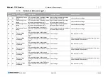
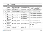
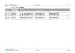
Flash 
Code 

Error 

Error message 
TopCon (Long) 

Description 

Possible Cause 

Counteraction 

14-8 

D7 

Number of devices 
in parallel config. 
does not corre-
spond with the 
given value 

The number of devices in parallel 
circuit does not match with the sys-
tem configuration.  

The module IDs are badly config-
ured.  

Consult manual to reconfigure module IDs to 
match the requirements.  

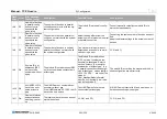
14-8 

D7 

Number of devices 
in parallel config. 
does not corre-
spond with the 
given value 

The number of devices parallel cir-
cuit does not match with the system 
configuration.  

default setting differs from the 
actual number of modules in serial 
or parallel connection.  

Connecting the same number of devices as speci-
fied. 
Adapt the Master settings to the actual number of 
devices.    

14-8 

D7 

Number of devices 
in parallel config. 
does not corre-
spond with the 
given value 

The number of devices in serial or 
parallel circuit does not match with 
the system configuration.  

One slave at minimum was not 
detected as a result of a commin-
cation or login error 

Cf. 6)  and C). 

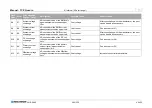
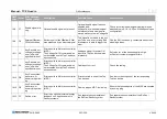
14-9 

D8 

All slave ID's or 
addresses (RSC 
on) have to be 
numbered without 
a gap 

The module IDs or addresses (RSC 
on) aren’t numbered consecutively 
without gap.  

The Module IDs or addresses 
(RSC on) aren’t numbered con-
secutively without gap. Refer to 
section “network” in manual for 
explanation of “without gap” (e.g. 
in parallel connection the expres-
sion “without gap” means that IDs 
= 00h, 10h, 20h, … are used.) The 
value 'ui-
CAN_MaxNumModuleParallel' 
must be set  identically in all mod-
ules. default value: 8. 

The module ID according the manual and the de-
sired configuation are set correctly. 

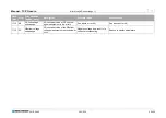
14-10  D9 

All HMI/RCU ID's 
have to be num-
bered without a 
gap 

The HMI IDs aren’t numbered con-
secutively without gap. 
From HMI firmware V5.15.00  the ID 
have to be only unique  

The HMI IDs aren’t numbered 
consecutively without gap. 

All HMI IDs must start with 01 and must be num-
bered consecutively without gap. 

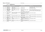
14-11  DA 

Number of slaves 
does correspond 
with the given val-
ue 

The total number of devices doesn’t 
match the default.  

Cf.  D6)  and D7). 

Cf.  D6)  and D7). 

Summary of Contents for TC.P Quadro

Page 1: ...TopCon series DC power supply Regatron AG Kirchstrasse 11 CH 9400 Rorschach Tel 41 71 846 67 67 Fax 41 71 846 67 77 www regatron com topcon regatron ch Distributor sticker Manual for model TC P Quadro ...

Page 2: ...indows XP Vista Windows 7 are trademarks of Microsoft Inc USA LabView is a trademark of National Instruments This information in this documentation corresponds to the development situation at the time of going to print and is therefore not of a binding nature Regatron AG reserves the right to make changes at any time for the purpose of technical progress or product improvement without stat ing the...

Page 3: ... From version V5 08 00 TopControl From Version V4 01 66 Error list From version V11 28 Table 1 Subject to technical change without notice xx valid for all sub versions General information on the manual Purpose of the manual This manual provides information on the usage of the TopCon TC P DC power supply It serves as instructions and as a reference work Famil iarise yourself with the contents of th...

Page 4: ...nformation 23 2 2 1 Supplying electrical power using the TopCon power supply 23 2 2 2 Model range overview of the standard models 25 2 2 3 Control and internal controller structure 27 2 2 4 Principle of the scope of operation authorisation concept 28 2 2 5 Parameterisation the process in principle 29 3 THE TOPCON QUADRO POWER SUPPLY SINGLE DEVICE 31 3 1 Technical data 31 3 1 1 Device layout views ...

Page 5: ...2 Analogue remote programming 74 3 3 3 3 Analogue remote programming switching on off the device 75 3 3 3 4 Analogue remote programming for current and voltage 75 3 3 3 5 Analogue remote programming for power limit and internal resistance simulation 76 3 3 3 6 Digital outputs relay contact 77 3 3 4 Diagnostic and control connection RS 232 DLL TopControl application 77 3 3 5 System internal communi...

Page 6: ...128 4 4 8 RS 232 to Ethernet converter option 129 5 MULTI UNIT SYSTEM 131 5 1 Introduction 131 5 2 Load connection on devices in multi unit operation 132 5 2 1 Sense function in a multi unit system 133 5 3 Internal system communication 134 5 3 1 Hardware required for the multi unit system 134 5 3 2 Interlock circuit in a multi unit system 134 5 3 3 Multi unit system with TopCon power supplies 136 ...

Page 7: ...176 6 4 5 2 Menu bar user level and functionality 177 6 4 5 3 Tabs user level and functionality 178 6 4 6 Using the software menu bar 179 6 4 6 1 Menu File 179 6 4 6 2 Menu Window 181 6 4 6 3 Menu Info 183 6 4 7 Using the software tabs 184 6 4 7 1 Tab CONTROL 184 6 4 7 2 Tab STATUS 187 6 4 7 3 Tab FUNCGEN option 189 6 4 7 4 Tab SCOPE 205 6 4 7 5 Tab CONFIG 223 6 4 7 6 Tab PROTECT 229 6 4 7 7 Tab A...

Page 8: ... PDSP 270 9 1 3 2 Output current 272 9 1 4 3 Output voltage 274 9 1 5 4 Supply 276 9 1 6 5 Temperature 280 9 1 7 6 Communication 282 9 1 8 7 Internal Modulator 285 9 1 9 8 Internal AD overrange 1 288 9 1 10 9 Internal AD overrange 2 290 9 1 11 A Internal AD underrange 1 292 9 1 12 B Internal AD underrange 2 294 9 1 13 C Login 296 9 1 14 D Configuration 301 9 1 15 E Configuration 2 304 9 1 16 F Mis...

Page 9: ...the rigorous application of specialist electrical rules The system is subject to the Low voltage directive it is to be operated by adequately trained and instructed personnel 1 1 1 Categorisation of the hazard areas The assessment of the effects of hazards from low voltage systems with a flow of energy for supply and possibly regeneration is divided into the following areas Fig 2 Categorisation of...

Page 10: ...ng it should be rigorously applied during all connection and wiring work Follow the rules 1 Electrically isolate 2 Secure against switching back on 3 Short circuit 4 Connect to earth 5 Report and instruct After shut down the short circuiting of the outputs and earthing are particularly important for safety reasons if reactive loads or loads that store energy rechargeable batteries capacitors ULTRA...

Page 11: ...itored endurance tests insulation fires and short circuits may be caused At particular risk are connectors switchgear and cable terminals Check these parts particularly carefully and at regular intervals Use wiring material suitable and stipulated for your application with the related insulation class Monitor your system actively or passively using appropriate sen sors or by monitoring parameters ...

Page 12: ...ge systems produce elec trical and magnetic fields However these fields comply fully with the usual standards Note however that particularly the EM fields from your cables and equipment connected could nevertheless produce interference on ob jects in the immediate area Note the following Keep data carriers and PC based measuring environments an adequate distance from live cables to prevent interfe...

Page 13: ...to some extent signifi cantly higher peak currents are to be expected during switching processes Unlike the TopCon low voltage system which is fully current limited in the case of stores containing large amounts of energy a short circuit or failure can be very serious Due to the high cur rents serious injuries and serious damage can be caused The following incomplete list indicates some this damag...

Page 14: ...y is dis sipated with the aid of forced ventilation to the rear of the TopCon pow er supply It is to be ensured that the rooms in which TopCon power supplies op erate are cool and therefore the heat produced can actually be re moved Active cooling is however generally unnecessary The forced ventilation discharges air from the rear side of the TopCon power supply It is to be ensured that there are ...

Page 15: ... transport of systems the following is to be noted It is not allowed to tip the system by more than 20 degrees Larger tip ping angles could cause mechanical damage to the carrying frame and the TopCon front panels As a rule the doors on the case for the sys tem should be closed during transport so that the case can absorb higher loads On moving the system using a forklift truck Depending on the de...

Page 16: ... against mechanical damage lifting using 2 better 3 carrying straps It is imperative you remove all cable connections prior to moving the system Note that between switching off the power supply and discon necting the power cables on the output side it is necessary to wait at least 15 min for discharging Keep all doors closed during the transport of cabinets Pay attention to protruding parts such a...

Page 17: ...3 Periodic overcurrents are to be avoided 4 The DC ripple currents produced on the load side are to be mon itored to avoid overloading filter capacitors in case of doubt ask the manufacturer 5 The system is always to be operated within the permissible tem perature range High temperatures will significantly reduce the service life of various modules 1 1 8 Ordinances and regulations Follow the mount...

Page 18: ...possibly hazardous situation that can result in serious injuries or fatality For a possibly hazardous situation that could result in damage to the product or another item in its surroundings Table 2 Basic hazard and warning information Further warning and hazard information Pictogram Meaning DANGER WARNING or CAUTION due to electrical power DANGER WARNING or CAUTION related to suspended load Table...

Page 19: ...Meaning Important information Table 4 Mandatory signs that are important for the operation of the device or the software General notes Pictogram Meaning Tip for working efficiently with the device Table 5 Additional information so that you can find possibly important information quickly ...

Page 20: ...n connection of the TopCon power supply to the PC 6 4 3 173 Table 6 Overview of getting started with the TopCon power supply We strongly recommend you to take the time to become familiar with the new TopCon power supply using these instructions Reading the instructions will result in the following advantages 1 Device check You will become familiar with the TopCon power supply and the TopControl ap...

Page 21: ...m page 62 Connect the control interface X105 to the 25 pin dummy plug device rear side The CAN bus for the device communication is connected Situation no RCU Remote Control Unit available The communication and interlock interface X101 on the rear side of the TopCon power supply is terminated using the Inter lock and CAN Term dummy plug 9 pin device rear side Situation RCU Remote Control Unit avail...

Page 22: ... supply Any direction of rotation is acceptable and the N conductor is not used 2 1 2 Switching on and off a TopCon power supply Switching on the device Switch on main switch On the front of the TopCon power supply in the form of a triple switch The TopCon power supply is booted The signal processors are initialised and a device self test per formed Can be seen on the HMI RCU during the login proc...

Page 23: ...ce simulation of up to 3 2 Ω is possible Output current Pmax Imax CV CP CC CV Voltage control CP Power control Power reduction CC Current control Output voltage Umax Fig 5 Voltage current and power characteristics of the regulated TopCon power supplies Here the maximum output values are the nominal output values Nominal signifies a constant maximum output value The maximum value can also include t...

Page 24: ...ies form the heart of even larger electrical power supply systems They contain all the necessary basic functions for stand alone opera tion however the multi unit operation connected in series and or paral lel of several power supplies with one or more loads is also possible See multi unit operation chapter 4 4 from page 122 ...

Page 25: ...P 20 65 400 S 0 65 0 32 0 600 19 x 9 U x 590 68 TC P 32 65 400 S 0 100 0 10 0 125 19 x 6 U x 495 42 TC P 10 100 400 S 0 100 0 16 0 200 19 x 6 U x 495 44 TC P 16 100 400 S 0 100 0 20 0 250 19 x 9 U x 590 64 TC P 20 100 400 S 0 100 0 32 0 400 19 x 9 U x 590 68 TC P 32 100 400 S 0 130 0 10 0 96 19 x 6 U x 495 42 TC P 10 130 400 S 0 130 0 16 0 153 19 x 6 U x 495 44 TC P 16 130 400 S 0 130 0 20 0 192 1...

Page 26: ...0 0 10 0 16 19 x 6 U x 495 42 TC P 10 800 400 S 0 800 0 16 0 25 19 x 6 U x 495 44 TC P 16 800 400 S 0 800 0 20 0 32 19 x 9 U x 590 64 TC P 20 800 400 S 0 800 0 32 0 50 19 x 9 U x 590 68 TC P 32 800 400 S 0 1000 0 10 0 13 19 x 6 U x 495 42 TC P 10 1000 400 S 0 1000 0 16 0 20 19 x 6 U x 495 44 TC P 16 1000 400 S 0 1000 0 20 0 25 19 x 9 U x 590 64 TC P 20 1000 400 S 0 1000 0 32 0 40 19 x 9 U x 590 68...

Page 27: ...590 68 TC P 32 500 480 S 0 600 0 20 0 40 19 x 9 U x 590 64 TC P 20 600 480 S 0 600 0 32 0 66 19 x 9 U x 590 68 TC P 32 600 480 S 0 800 0 20 0 32 19 x 9 U x 590 64 TC P 20 800 480 S 0 800 0 32 0 50 19 x 9 U x 590 68 TC P 32 800 480 S 0 1000 0 20 0 25 19 x 9 U x 590 64 TC P 20 1000 480 S 0 1000 0 32 0 40 19 x 9 U x 590 68 TC P 32 1000 480 S 0 1200 0 20 0 20 19 x 9 U x 590 64 TC P 20 1200 480 S 0 120...

Page 28: ...uations and in particular the residual ripple The ripple is at 300Hz on 3x400V 50Hz systems 360Hz on 3x480V 60Hz systems 2 2 4 Principle of the scope of operation authorisation concept TopCon power supplies have numerous functions The actual scope of operation available is dependent upon The authorisation level user level The functions enabled options During this process all interfaces are used to...

Page 29: ...d in special manu als See gridfile listing page 214 Depending on the type of data the data are saved differently internally and processed internally by the power supply Peripherie DSP RAM Main DSP RAM Modulator DSP RAM I O RS 232 Power Amplifier Flash EEProm PC Software TopControl Gridfiles Gridfiles Gridfiles TopCon Quadro 4 5 6 3 1 2 7 Fig 7 Scheme setting the parameters for the control of the T...

Page 30: ...the Main DSP Only after the entry of the command Store Settings are the data saved 6 in the non volatile flash EEProm 5 Saved data are retained When the power supply is restarted the new parameters are automati cally loaded from the flash memory 5 into the RAM for the Main DSP 6 Data that are not saved will be lost If temporary parameters are only written to the RAM and are not saved in the flash ...

Page 31: ...evice 3 1 1 1 The front side of the device 2 3 1 Fig 8 Overview of the front side of the TopCon Quadro power supply 6 U with HMI Front side of TopCon Quadro power supply cf Fig 8 1 TopCon standard interface With address selection interface RS 232 status LED For further information see chapter 3 1 1 2 page 32 2 HMI control panel option For further information see chapter 3 1 1 3 page 33 3 Main circ...

Page 32: ...Standard covered by plastic caps AH Upper address range AL Lower address range 2 RS 232 interface For operation via a PC using the TopControl application 3 DEVICE LED indicator Indication of the device status Green POWER Yellow STATUS WARNING Red ERROR 4 CONTROL LED indicator Green LED illuminates in front of the related label for the operating state VOLTAGE Voltage control CURRENT Current control...

Page 33: ...m screen 5 MENU button Opens the main menu 6 ON OFF switch ON Green LED illuminated On reaching the operating state the output value set is present on the device output OFF Green LED is off device output is electrically isolated 7 REMOTE switch Change over as to whether the TopCon power supply is to be remotely con trolled Deactivated Red LED off HMI is ready for entries Activated Red LED illumina...

Page 34: ...meters 3 Regulated fans As an option there may also be connections for the water cooling LC option 4 Mains connection 300 400 480VAC 5 Blind cover strip Can be removed for further interfaces 6 Interfaces D Sub Upper area CAN communication interfaces X101 X102 Lower area analogue and digital interface X105 7 Auxiliary fuse For the internal 24 V supply Only for the device variant 10 16 kW On the dev...

Page 35: ...00 VAC 3 phase 20 Aeff 32 Aeff 40 Aeff 60 Aeff Model 480 VAC 3 phase 17 Aeff 27 Aeff 33 Aeff 50 Aeff Inrush current 1 15 A Nominal current Circuit breaker 2 25 A 32 A 40 A 63 A Breaking capacity Circuit breaker 2 10 kA Power factor cos φ 0 85 0 87 Harmonics content 0 72 Efficiency approx 90 92 93 95 Power loss approx 1 1 kW 1 4 kW 1 5 kW 2 0 kW Table 15 Electrical parameters for the various TopCon...

Page 36: ...value as standard 1 2 or optional 3 2 Accuracy measurement resolution 1 Analogue input and output 0 1 at 10 bit resolution Actual voltage 0 025 at 12 bit resolution Actual current 0 025 at 12 bit resolution Temperature measurement 0 2 C Table 18 Measuring accuracy of the TopCon power supply 1 Absolute value or referred to nominal values Times Starting time Control electronics 1 5 0 s Power section...

Page 37: ...rs 1 Referred to nominal values with Ohmic load 3 1 5 Protection functions Overvoltage protection In operation as current source Voltage limiting In case of malfunction Electronic inhibit Response threshold 1 2 0 110 Response time 2 50 µs 1600 ms Table 21 TopCon power supply overvoltage protection 1 Referred to nominal voltage 2 Adjustable Overcurrent protection In operation as voltage source Curr...

Page 38: ...r operation Max 1000 m above sea level Reduced power Max 2000 m above sea level Ingress protection IEC 60529 Basic version IP 20 Appropriate case 2 Up to IP 43 Utilisation category Protection class I Overvoltage category I I I Degree of soiling 2 Vibration 2 Up to 2 g Table 23 1 For versions with expanded characteristics please contact your TopCon sales partner 2 Tested in accordance with standard...

Page 39: ...ub 9 pin front side Table 24 Information on the interface X301 RS 232 3 1 7 2 Analogue and digital inputs and outputs X105 Task interface X105 Set value specification U I P Ri actual value output U I Digital remote control Safety circuit interlock Pin definition for the interface X105 see chapter 3 2 4 7 page 64 Analogue inputs Configuration Quantity 4 can be configured to a certain extent sin gle...

Page 40: ...r information chapter 3 3 3 2 page 74 Reference output Configuration Quantity 1 Output voltage 10 VDC Output current Max 10mA Reference ground Common with 24 V control voltage Physical connections On X105 pin 6 Table 27 Reference output on interface X105 Further information chapter 3 3 3 2 page 74 Digital inputs Configuration Quantity 3 can be configured to a certain extent Input voltage active 10...

Page 41: ...ce X105 Further information chapter 3 3 3 6 page 77 3 1 7 3 CAN communication interfaces X101 X102 Tasks Communication between the devices in multi unit operation Safety circuit interlock Terminating resistor Pin definition for the interface X101 X102 chapter 3 2 4 7 page 64 Interfaces X101 X102 on the device rear side 1 X101 interface D Sub 9 pin For connecting interlock or terminating resistor t...

Page 42: ...to controller and earth Same as the device power output Physical connections Plus and minus pole earth Table 31 Short description of the interface X104 Further information on the sense function Single devices chapter 3 2 4 3 page 54 Multi unit system chapter 5 2 1 page 133 3 1 8 Mechanical properties 3 1 8 1 Device weight Weight power class TC P 10 TC P 16 TC P 20 TC P 32 Weight 42 kg 44 kg 64 kg ...

Page 43: ... 52 3 3 1 8 2 Installation height 6U for TopCon power supplies with 10 16 kW Rear view 2 62 B 2 65 465 A 190 7 Fig 12 Rear view of the TopCon power supplies with 6 U Side view 265 22 5 2 262 452 38 5 9 Fig 13 Side view of the TopCon power supplies with 6 U ...

Page 44: ... 3 1 8 3 Installation height 9 U for TopCon power supplies with 20 32 kW Rear view 399 394 B 120 6 A 101 6 101 6 465 Fig 14 Rear view of the TopCon power supplies with 9 U Side view 523 5 9 2 399 17 9 42 394 Fig 15 Side view of the TopCon power supplies with 9 U ...

Page 45: ...ystems and machines with built in TopCon power supplies remains with the manufacturer of the system or ma chine On the usage of the electrical power supply in certain application areas the related applicable standards and health and safety regulations are to be followed 3 2 2 Safety information Possible mortal danger due to electric shock Avoidance Never connect or disconnect electrical connection...

Page 46: ...ies are installed in standard cases or switch cabi nets either separately or in multi unit systems In the standard design TopCon power supplies are intended to be in stalled in standard 19 cases and switch cabinets with an external air flow In this case they are to be placed on rails or shelves and fastened at the points provided on the front panel Number of screws For 6 U devices typically 4 x sc...

Page 47: ...rature and humidity see chapter 3 1 6 page 38 1 2 2 3 2 4 4 Fig 16 Scheme of the passage of the air on installation in a cabinet case 1 Air supply 2 Air exhaust 3 Depth to the rear wall 150 mm 4 Air short circuit must be prevented Table 32 Schematic illustration of the cooling air flow For the supply and removal of cooling air sufficiently large suitable cases with corresponding inlet and outlet o...

Page 48: ...wall During this process an air short circuit 4 must be avoided Directly drawing back in discharged cooling air Air filter If the TopCon power supplies are to be operated in an environment with medium or heavily soiled air the cooling air supplied must be filtered ei ther externally e g on entry into a switch cabinet in the cabinet door or directly at the devices so that inadmissible deposits of d...

Page 49: ...f the modules and documentation supplied must be checked 1 Do the type plates match the order and delivery documentation 2 Are the device nominal data suitable for the intended application 3 Do the cables connector supplied match the intended connections During the installation work pay particular attention to the following 1 Never connect or disconnect electrical connections while they are live 2...

Page 50: ...function the following conditions must apply Large area earthing suitable for EMI Shield mains and load connection Depending on load and installation situation Connect both ends of shields to earth Depending on load and installation situation Interference immunity The system must be fully earthed encompassing all parts and earthed suitable for EMI Correct earthing and shielding of the cable connec...

Page 51: ... and load connection Depending on load and installation situation Connect both ends of shields to earth Depending on load and installation situation 3 2 4 2 System overview connections Block diagram The mains voltage is rectified and smoothed in a DC intermediate circuit with capacitors From this smoothed voltage a high frequency AC volt age is generated using a full IGBT bridge in the power secti...

Page 52: ... 5 8 pol Directly screwed tight on fixing rail 5x0 75 5x0 75 J4 J10 IG BT B Thyristor J1 6 2 2x0 75 J16 1 G K X1 20 X1 21 J2 3 J2 2 J2 1 S cr e en 2x0 7 5 S hiel ding X103 Sen se White Brown X20 8 X20 8 X20 7 X 207 X205 X2 05 X403 F L1 L2 L 3 F C D E F P E P E P P J18 IGB T A Outpu t Mains X105 X102 X1 01 X106 Backwards I nterlock Emergency Dig ital Contro l I O RS 42 2 optiona l Je CAN Interlock ...

Page 53: ...to the power line earth and output The analogue inputs and outputs are isolated in relation to the power line earth output and digital interfaces The RS 232 interface is isolated in relation to the power line earth output and controller The connections given above are described in more detail in this sec tion Name Interface Mains connection 3 400 480 VAC Sense X103 remote voltage sensor Correction...

Page 54: ...K option 2 The external main switch is mostly used for devices in a multi unit system in a switch cabinet Fuse F 1 In case of cable lengths over 3 m a fuse must be included in the circuit in accordance with VDE636 The rating is to be selected as appropriate see Table 34 page 54 Cable cross section The external cables must have the necessary cable cross section see Table 34 page 54 Mains connection...

Page 55: ...function in multi unit systems in the chapter on multi unit systems See chapter 5 2 1 page 133 Characteristics of the sense function On the usage of the sense function the following characteristics apply to the overall system The controller compensates for losses that result in particular due to high load currents and high cable resistances The load cable may be interrupted in operation The maximu...

Page 56: ...coupling of electrical interfer ence onto the sense input Increase the interference immunity by means of simple measures Simply twist the sense cables Lay the sense cables physically separate from power cables Software requirements The following conditions must be met for the sense function to be sup ported and so that it can be activated Main DSP firmware from V4 11 33 TopControl application from...

Page 57: ...nce of the parameters see chapter 6 4 7 5 page 223 1 2 3 Fig 20 Configuration of the sense function in TopControl Sense actual value indication On the activation of the sense function the following indications alter nate CONTROL tab The labels Output Voltage 1 and Output Power 1 change to Sense Voltage 2 and Sense Power 2 2 1 Fig 21 Indication change between output voltage and sense voltage STATUS...

Page 58: ... voltage via the analogue interface X105 With the sense function activated the analogue sense voltage actual value can be used for the indication via the analogue interface X105 For further information on the pin definition of X105 see chapter 3 2 4 7 page 64 Sense function indication change On the CONTROL tab If the corresponding sense actual values cannot be achieved the sense indication voltage...

Page 59: ...ONFIG tab Max voltage drop is in sufficient to compensate for the voltage drop over the load cable The required sense voltage is not reached The maximum module voltage allowed is insufficient to achieve the required sense voltage The required sense power is not reached The maximum module power allowed is insufficient to achieve the required sense power ...

Page 60: ...1200 V 2 5 4 6 10 Table 35 Cross section sizing for the load cable as a function of the output voltage For cable lengths of more than 5 m the next size cross section up should be selected to keep the voltage drop over the load cable in lim its 3 2 4 6 System internal CAN communication X101 102 TopCon power supplies that are operated in a multi unit system require system internal communication via ...

Page 61: ... CAN 2 CAN_L I O CAN low 3 GND_CAN O CAN common 4 5 6 GND_CAN O CAN common 7 CAN_H I O CAN high 8 0 VDC I O O Auxiliary supply common 9 24 VDC I O O Auxiliary supply 24 VDC Shield connected to earth Table 36 Pin definition on the interfaces X101 X102 as per Fig 26 Recommended cable characteristics for the system communication Properties Description Characteristic impedance 120 20 Cable cross secti...

Page 62: ...at the start of the CAN multi unit system 3 CAN Term D Sub 9 pin dummy plug Label X102 CAN TERM Is connected to interface X102 on the rear side of the device at the end of the CAN multi unit system Table 38 Dummy plugs and their labelling Only one CAN Term is allowed to be connected to a single device Independent of whether X101 or X102 is used Establishment of communication connection TopCon with...

Page 63: ...OFF RCU 1 4 3 2 TopCon Netzgerät mit HMI ohne HMI TopCon Netzgerät X102 X101 X102 X101 Fig 28 Circuit diagram for TopCon with HMI left and without HMI right No Function Dummy plug used Device Interface 1 Interlock CAN TERM Dummy plug X101 TopCon RCU X101 2 Interlock Dummy plug X105 TopCon X105 3 CAN TERM Dummy plug X102 TopCon X102 4 CAN CABLE TopCon RCU X101 Table 39 Allocation of components to F...

Page 64: ...pecification are connected to a 25 pin D Sub connector female on the rear of the de vice Pin 1 Pin 14 Pin 13 Pin 25 Back panel Fig 29 Pin arrangement at analogue digital interface X105 Sub D 25 pin female Pin Signal I O Description 1 AGND I Analogue ground for pins 2 4 14 16 2 VREF I Voltage setpoint input 0 10 V 3 IREF I Current setpoint input 0 10 V 4 IACT O Current feedback output 0 10 V 5 0 VD...

Page 65: ...osed 23 WARN_c 2 O Relay output 3 common 24 INTERLOCK_IN_ I Input Interlock 25 24 VDC O 24VDC I O Aux power output 24 VDC max 0 2 A Table 40 Pin definition for the X105 interface 1 Pin 5 0 VDC is used as the reference earth for pin 25 24 VDC and is connected internally to the equipotential bonding via a 1 k resistor to earth 2 Maximum switching current 1 A maximum switching voltage 24 V 3 2 4 8 In...

Page 66: ...n multi unit systems the interlock circuit is interrupted immedi ately on the operation of an EMERGENCY STOP All devices in the multi unit system are shut down simultaneously X105 Suitable for an external EMERGENCY STOP button on a sin gle device The interlock contact is interrupted on the local sin gle device In the multi unit system the shutdown signal is only passed on via the internal device c...

Page 67: ... power supply On the rear side option If the device is part of a multi unit system or a Q14 ReGen sys tem and it is installed in a switch cabinet the interface is often fit ted on the rear side of the device The RS 232 interface on the front side of the TopCon power supply cannot be operated at the same time as other interface options Pin definition for the RS 232 interface TopControl end PC end P...

Page 68: ...page 54 Loads connected with correct polarity For further information see chapter 3 2 4 5 page 60 Control signals connected correctly For information on X101 X102 see chapter 3 2 4 6 page 60 For information on X105 see chapter 3 2 4 7 page 64 Interlock emergency stop circuit wired For further information see chapter 3 2 4 8 page 65 3 2 6 Switching on the device Condition All external control signa...

Page 69: ... 6 page 78 If the state machine remains in the ERROR state after a re peated start attempt look for the reasons for the error using the TopControl application and take the necessary corrective measures Parameterisation If possible do not make any changes to the factory settings as the fac tory settings take into account your needs the operation foreseen and your individual applications in the majo...

Page 70: ...rmation see chapter 6 4 7 1 page 184 Check the output voltage or current to ensure it matches the set values Please note that depending on the configuration of ramp functions the set values specified may in some circumstances only be reached after the related ramp functions time have been completed Error free state After you have set the set values the following occurs in the error free state The ...

Page 71: ...Y STOP switch with external voltage source With interrupted interlock circuit The power stage is switched off directly via a hardware link The controller remains switched on The device changes to the state Error To work using the TopCon power supply or a system with TopCon modules check that the interlock circuit is actually closed Ensure that the correct dummy plug has been used for the terminati...

Page 72: ...was switched on first takes over the control If several active HMI are switched on at the same time the se lection is random The HMI RCU interface can be set to passive such that it does not make any attempt to take control 2 Analogue interface X105 If the HMI is set to passive and there is a high level on pin 20 the analogue interface takes over control For further information see chapter 3 3 3 p...

Page 73: ...e by means of the following signals Rising edge from 0 V to 24 V If the ANALAOG_REFERENCE_SELECT signal has already reached the high level of 24 V on power up For information on the pin definition see Table 40 page 65 Pay attention to the interface hierarchy Activation of the analogue interface with HMI option for remote control Using the analogue selection in the HMI the control over the system c...

Page 74: ...lec tion using the Store Settings 4 button 3 3 3 2 Analogue remote programming Isolation of the signal inputs All four analogue inputs for current IREF voltage VREF RREF and power PREF are fully isolated as a result external isolating amplifiers are not required Reference ground The reference ground is common for all analogue inputs and must be connected to the reference potential of the supplying...

Page 75: ...d on 24 VDC are present Device switched off open connection Table 43 Switching states VOLTAGE_ON Use dummy plugs supplied In the simplest configuration the related dummy plug must be used this plug is fitted to interface connection X105 For information on dummy plugs see chapter 3 2 4 6 page 62 3 3 3 4 Analogue remote programming for current and voltage If this set value setting is not required th...

Page 76: ...t Internal resistance set value set value Fig 36 Analogue specification of power limit and internal resistance Analogue set value specification using potentiometers 1 Analogue set point specification using external sources 2 Pin Analogue control Function 14 Power limit PREF 10 0 V or 10 0 kΩ Output power Pmax Pnom 0 100 where PREF 0 100 15 Internal res RREF 0 10 V or 0 10 kΩ Internal resistance RR...

Page 77: ...RS 232 DLL TopControl application The diagnostic and control connection can be in the following positions on the device Built in on the front Built in on the rear option If this option is available it is not possible to use the interface on the front at the same time The RS 232 interface is the main access point for digital control infor mation Typically the connection is made via a PC using the T...

Page 78: ...e two interface connections For information on dummy plugs see chapter 3 2 4 6 page 62 3 3 6 Internal system status and troubleshooting This section explains the internal control processes It will help you to better understand the system messages in particular warnings and er ror messages provided by the device in various ways 3 3 6 1 Monitoring device internal processes The internal processes are...

Page 79: ...electrically isolated fans off 1 ST_STOP Stop state for software update FATAL_ERROR Internal communication failed Table 47 Internal system states 1 Depending on the temperature the fans may continue to operate at reduced speed The device state is output to the exterior on the following interfaces Light emitting diode on the front panel Green POWER Yellow STATUS Red ERROR For information on the con...

Page 80: ...ooting 4 Flashing if a warning is active at the same time 5 The three LEDs are flashing together internal communication failed Description of the shutdown process On devices with 20 kW and 32 kW Changing the position of the main switch does not shut down the Top Con power supply immediately instead a shutdown process is initiated In particular the discharge of the internal capacitors takes a certa...

Page 81: ...ion current monitoring concept The current limiting is intended on the one hand to protect the device above all the semiconductors against damage on the other hand cer tain monitoring functions can also be used to protect the load connect ed Monitoring Protection in case of Implementa tion Time range Short circuit monitoring by IGBT driver Transformer satura tion hardware faulty Hardware level fix...

Page 82: ...rrors are indicated sequentially as flashing codes on the red ERROR light emitting diode on the front of the device Warnings are indicated via the yellow STATUS light emitting diode on the front panel Output in the form of flashing codes is important in multi unit sys tems as in this case as a rule only one TopCon power supply has a HMI user interface However all TopCon power supplies have the LED...

Page 83: ... the light emitting diodes Count the flashes Group error code 16 Detail error code 3 Reference to the error code list shows that an interlock error has been detected F 2 Note that the error coding is in hexadecimal FHex 1510 3 is the third element in 0 1 2 3 The indication on the HMI or in TopControl is 0 15 or 0 FHex The flashing code on the ERROR LED does not have a zero and therefore assumes th...

Page 84: ... OK Alarm relay normally closed normally open For further information see chapter 3 3 3 6 page 77 The following VLS functions can be selected Exceeding a threshold Dropping below a threshold Entering a window Defined value range is reached Leaving window Defined value range is left Each threshold can also be assigned a hysteresis range above or below a threshold value A value of zero will deactiva...

Page 85: ...ng below the threshold 2 Entering a window leaving a window 2 1 Output quantity Output quantity upper threshold switching threshold switching threshold upper threshold switching threshold switching threshold lower threshold switching threshold switching threshold lower threshold switching threshold switching threshold unchanged Hysteresis 0 active area inactive area unchanged Hysteresis 0 unchange...

Page 86: ...ctive to inactive delay 20 ms the hysteresis set 0 V The current curve exceeds the threshold 1 as a consequence it is in the active range The active counter now counts up as per the limit val ue set inactive to active delay 2 In this example the current drops back below the lower hysteresis threshold 3 From this point in time the counter counts down 4 From point 5 the monitored current increases a...

Page 87: ... software require ments ReGen ResACT ACLF VLS can be programmed using the TopControl application supplied from V4 01 35 The data are then transferred directly to the TopCon power supply VLS then operates independent of the TopControl application i e continued connection to the PC is not necessary 2 1 3 4 5 6 7 8 9 Fig 41 The VLS Settings window is opened via the CONTROL 1 tab and the Edit VLS sett...

Page 88: ...is outside window Leaving a window 5 Limits text boxes Related thresholds and hysteresis for the selected range Depending on the selection in 4 different text boxes are activated 6 Relais switching behavior text boxes The adjustable switching delay between the active and the inactive range helps to ignore brief fluctuations in the output value 7 Relais switching behavior list box switching state S...

Page 89: ...oftware options Functions that are enabled using an enable key Interface options Additional hardware interfaces mostly with additional software or protocols In this chapter In this chapter options are described with a varying degree of detail Options that relate to TopCon power supplies in a multi unit sys tem are described in a dedicated chapter For further information see chapter 4 4 page 122 Fr...

Page 90: ...n IRXTS 4 2 9 110 Linear post processing unit TC LIN 4 2 10 112 Specification extensions Mil spec ruggedized 4 2 11 114 Table 52 Hardware and system options for TopCon Software option Name Chapter Page Function generator TFE 4 3 1 115 PV simulation Solar array simulator SAS Control 4 3 2 118 Rechargeable battery management Akku Control 4 3 3 121 Table 53 Software options for TopControl Interface o...

Page 91: ...era ture if the cooling liquid is correspondingly pre cooled or is con nected to a larger cooling water system A power loss primarily occurs in the following device elements Power semiconductor elements with 90 95 of the total power loss These elements are fastened to a heat exchanger The heat is removed from the interior of device using a cooling medium Inductive and resistive elements with 5 10 ...

Page 92: ... Position of the hose connection fittings on a 6 U device Dimensions on 9 U devices 186 5 483 399 88 5 60 1 2 Fig 43 Position of the hose connection fittings on a 9 U device Cooling liquid supply connections 1 Input standard G hose connection fitting 2 Output standard G hose connection fitting Table 55 Connections on 6 U and 9 U TopCon power supplies ...

Page 93: ... ing liquid 2 0 l min 2 5 l min Maximum permissible continuous outlet temperature KM 2 40 C 2 5 l min 50 C 5 l min Maximum permissible inlet temperature KM 2 25 C 2 5 l min 40 C 5 l min Table 56 Characteristics of the liquid cooling 1 On the usage of cooling liquids with significantly different specific heat capacity the figures must be modified accordingly 2 For other temperature values please co...

Page 94: ...hanger surfaces Electrolytic and or chemical corrosion The deposition of fine sludge Coating with foreign substances and as a result degradation of the heat transfer Recommended characteristics of water as a cooling medium Parameter Unit Limit value with single flow 1 ph value 6 8 Total hardness dH 2 15 Carbonate hardness dH 2 6 Non carbonate hardness mmol l 3 1 60 Carbon dioxide free mg l 3 Organ...

Page 95: ...cooling liquid pressure is 4 bar 4000 hPa 2 Recommended range Connection with quick release isolating valves Heat sink with internal pipework ready for connection of cooling liquid on site at the rear side of the device plus 2 quick release isolating valves on customer request inside diameter 6 mm Pressure difference Flow rate quick release isolating valves 0 06 bar 2 5 l min 0 15 bar 3 5 l min 0 ...

Page 96: ... The formation of bubble in the cooling circuit is minimised 3 Connect the device to your cooling circuit 3 1 2 Fig 44 Examples for liquid cooling using cooling liquid 90 quick release isolating valves 1 on a 32 kW power supply Hosing 2 and pipework 3 on a 32 kW power supply in a device cabinet 4 2 1 5 Connection of a connection fitting The G 1 2 adapter makes it possible to replace the hose conne...

Page 97: ...for the cooling liquid connection Damage possible Due to leaking cooling liquid Avoidance Close the main cooling liquid line to the device before you remove the hose connection fitting Have a container and cloths at hand to be able to collect around 1 2 l of cooling liquid Remove the hose connection fitting On the removal of the connection fitting 1 store the copper ring 2 in a safe place Free the...

Page 98: ...xample fine metal dust can cause lasting degradation of the func tion of the power supply and even damage 2 1 Fig 46 TopCon power supply 9 U with air filter 1 and without air filter 2 On the usage of filter mats with excessively small pores or in case of excessive soiling the TopCon power supplies may be further derated Air filter sizes Air filters are available in two versions depending on the po...

Page 99: ... The mechanically attached non conductive cover 3 is clipped to a metal bracket 2 to cover the current bars 1 The metal bracket is first attached to the rear side of the TopCon power supply around the output current bars 2 3 4 1 Fig 47 Protection against physical contact on the power outputs on 9 U devices PACOB components and position 1 Current bars TopCon power supply output 2 Metal bracket Scre...

Page 100: ...contact on the power outputs on 6 U devices PACOB components and position 1 Current bars Output on the 6 U TopCon power supply 2 PACOB protection against physical contact insulating plastic sleeve Is fitted over the connected TopCon current bars 3 Cable connected to current bar Table 62 PACOB components and position on 6 U devices ...

Page 101: ...present on the primary side of the transformer On the secondary side 3 this voltage is rectified and smoothed such that the resulting DC voltage is present at the output terminals QBH DC i ntermediate UP rim CSym IP rim QAH CS1 Inp ut rec ti fie r L1 L2 L3 3 2 1 Fig 49 Overview of the power circuit Safety related aspects The overall system can only transmit power if there is an AC voltage present ...

Page 102: ...abled and disconnected by an externally controlled safety relay A positively driven contact is used for the external monitoring of the correct function of the safety relay The state of the EMERGENCY STOP relay is also monitored by the main DSP 2 Signal circuit The start stop command can come via the hardware interface or one of the software interfaces The main DSP processes this command and proces...

Page 103: ... safety device is the product PNOZ manufacturer Pilz Fig 51 Example TopCon wiring with PNOZ safety switchgear TopCon N o t a u s r e l a i s P N O Z 1 24VD C 230VAC 230VAC 50Hz N etzgerät Z weikan aliger NOT AUS Schalter Schnitts telle MainDSP Regler On OFF Opto k oppler Pin 4 P in 9 P in 3 Pin 5 Sic herheit ss chnitt st el le X107 ...

Page 104: ...ng power system Q4 regeneration Energy is returned back to the supplying power system and not converted into waste heat ReGen systems exploit the following advantages of the regeneration of energy to the power system The power consumption is reduced In many cases the saving is considerable There are financial savings Improvement of environmental aspects The basic problem As a rule power supplies b...

Page 105: ... 480V 3 TopCon Power Supply Load DC output Fig 52 Principle of operation of a ReGen system The signal processors in the TopCon power supply control the regener ation in real time Thanks to the new control strategy Single Authority Control ambigui ties and dead zones in the area of low powers can be reliably avoided The high quality of the regenerated power is achieved by Optimal operation of the i...

Page 106: ... operated via a binary signal that is sent from the TopCon power supply to the discharge device Normally the discharge device can be integrated into the TopCon power supply However very high power discharge device resistors must be positioned externally depending on the load and requirement UOUT UDISCH UD_OFF UD_ON ON OFF tD_ON UIST USOLL t t Fig 53 Sketch of the switching threshold hysteresis of ...

Page 107: ...ing the TopCon control to a limited extent For example the output voltage will not drop fast enough or may even be increased The solution This undesirable behaviour can be avoided if a Down Programming Unit DPU is connected in parallel with the load The unit is activated if the output voltage current does not follow the internal control Typical usage of the DPU In the case of a load with a storage...

Page 108: ...ted or reactive power from the load side The solution On systems with low voltages and power with simultaneously high sys tem dynamic performance the ResACT system operates similarly to the ReGen system Controlled by the TopCon power supply a second system E Load helps to en sure the power returned from the load Load is consumed The power is converted into heat Compared to the ResPas system howeve...

Page 109: ...he TopCon system only provides unipolar volt ages at medium powers at low frequencies However there are cases where the TopCon power supply can only not be used because a bipo lar voltage source is required A normal frequency generator can how ever as a rule not provide enough power The solution The ACLF system combines a TopCon power supply or a multi unit system if higher powers are required wit...

Page 110: ...l resistance simulation 1 TopCon source with no load and internal resistance 2 TopCon source with load and internal resistance Example calculation The TopCon power supply simulates a rechargeable battery with an in ternal resistance RInternal 0 8 Ω and a no load voltage UL 48 V A load current I 12 A flows the voltage at the load ULoad is reduced by 20 from UL Differentiation between cases no load ...

Page 111: ...tions Internal resistance mΩ Standard internal re sistance 0 to 1000 With option IRXTS 0 to 32000 Customer request 1 Over 32000 Table 64 Overview of internal resistance simulation options 1 In consultation with Regatron support You can obtain further information from your sales partner and Rega tron support ...

Page 112: ...supply The difference between the output voltage output from the TopCon power supply and the load voltage is used as a controller amplitude re serve for the fast TC LIN linear controller Typical values are between 40 V and 50 V The TC LIN operates in principle as a current controller At very low cur rents the TC LIN switches to the voltage controller mode so that accu racy is maintained also in th...

Page 113: ...age V Input current A Output current A TC LIN SER 26 1000 26 1000 13 26 1 13 26 1 TC LIN SER 40 1000 40 1000 20 40 1 20 40 1 Table 65 TopCon TC LIN model range 1 The first value is the alternative current range half the second the standard current range full Higher power can be achieved by connecting in parallel in a multi unit system inverster TopCon TC P TopCon TC LIN TopCon TC LIN Load inverter...

Page 114: ...ce with IEC 60068 2 64 Extension of the temperature range e g 40 C to 55 C Condensation test visual tests function test In the case of such requirements or similar requirements please con tact your sales partner or Regatron support Example properties of a modified TopCon power supply No Short form Description of the test result Mechanical shock 1 In accordance with IEC 60068 2 27 30 g 11 msec 3 sh...

Page 115: ...ation of this option For a description of the parameter entry for the function generator TFE via the TopControl application see chapter 6 4 7 3 page 189 For information on calling defined function sequences for the function generator via the HMI see Table 87 page 162 Function Block FB A function block can be formed from various base functions for voltage current and or output power The following f...

Page 116: ...ined The following events Trigger mode can trigger a function sequence VOLTAGE ON Voltage on As soon as the output power is activated at the output of the power supply Manual triggering Manual Manual triggering is possible n the TopControl application or with the aid of the HMI RCU Analogue interface X105 High level on X105 19 If there is a high level on pin 19 of the interface Definition of refer...

Page 117: ...ined via this interface Maximum number of function sequences in the TopCon power supply Up to 256 time dependent standard function sequences In the case of arbitrary time dependent user defined func tion sequences the number is dependent on the number of points A maximum of 1000 points is possible In the case of arbitrary function sequences user defined AAP the number is dependent on number of poi...

Page 118: ...r up a previously saved function sequence is loaded au tomatically Several function sequences can be saved 64kB of memory are available for this feature Without user defined curve shapes up to 256 function sequences can be saved In the case of user defined curves 4 bytes per point the number reduces accordingly The function sequences are saved in a sequence number 1 1000 that can be selected and c...

Page 119: ... supply without AC polarity reverse bridge interprets negative set values as zero 4 3 2 Solar Array Simulator SAS option SASControl Function The function generator for the TopCon power supply is switched to the AAP mode with a function I f U and can behave like a solar panel in accordance with this function By overlaying on another AAP characteristic curve the effect of solar ir radiation and temp...

Page 120: ...vement of dynamic performance using the TC LIN linear se ries controller A further improvement in the dynamic performance of the system is provided by the usage of the downstream TC LIN linear series control ler The linear series controller communicates with the TopCon power supply While the TopCon power supply defines the signal coarsely the TC LIN modifies the output signal with high dynamic per...

Page 121: ...t applies in general only at higher loads On small energy stores it is often sensible to discharge using a dissipative load because energy recovery to the grid is only economical from higher quantities of energy The characteristics for the rechargeable battery management in the Regatron software Accu Control are Feature for charging and discharging a rechargeable battery via constant current or co...

Page 122: ...nformation X X X X Reference values set specify X X X X Read actual values X X X X Read errors warnings X X X X Function generator standard functions sine square triangle X 1 2 X 1 2 X 2 X 2 Function generator AAP function call X 1 2 X 1 2 X 2 X 2 Function generator AAP function define X 2 SCOPE function X Table 69 Overview of dependencies between task category and interface 1 Increased effort req...

Page 123: ...o interfaces are possible and function together autonomous The two interfaces are not possible at the same time Not foreseen possible at the moment The two interfaces are possible CAN CANOpen interface is dominant 1 External Profibus to RS 232 converter 2 External converter not bidirectional Functionality must be checked 3 External Ethernet to RS 232 converter P Only one interface is allowed to be...

Page 124: ...r side of the device It can be retrofitted to a device or be already installed on delivery Combination with other interfaces The RS 232 REAR interface takes over the tasks of the RS 232 interface on the front side of the device Technical characteristics Type of bus connection plug D Sub 9 pin Interface standard in accordance with EIA 232 For technical data and information on function see chapter 3...

Page 125: ...designed as D Sub socket 9 pin Interface standard ITU T V 11 Function The RS 422 interface is used for high speed data transmission over large distances The serial data are transmitted as a voltage difference between two cor responding wires without a reference to ground For each signal to be transmitted there is one pair of cores that com prises an inverted signal wire and a non inverted signal w...

Page 126: ... REAR interface takes over the tasks of the RS 232 interface on the front side of the device Technical characteristics Type socket for USB plugs of type B see Fig 64 USB in terface 1 in combination with RS 232 REAR interface 2 Interface standard USB 1 1 Function This is a serial interface and corresponds to the functionality of the RS 232 interface The USB interface is used for the transparent tra...

Page 127: ...mands instead Technical characteristics Type of bus connection plug D Sub 9 pin CANOpen protocol CiA standard 301 V 4 02 Function Unlike the internal CAN bus in the device which is responsible for the internal flow of information in the device and that is supplied as stand ard the optional CAN CanOpen interface is used for the connection of devices from other manufacturers As a real time system th...

Page 128: ...e time Combination with other interfaces is not possible Technical characteristics Type of bus connection socket Centronics 24 pin SCPI command set standard IEEE488 2 expanded with TopCon control commands Function Using commercially available Centronics connectors and the IEEE488 interface TopCon power supplies can be operated independently Dur ing this process specific TopCon control commands are...

Page 129: ...t case 2 view of front and underside and benchtop case 1 Converter variants Benchtop case 1 without clamping fitting but with feet and 9 VDC power supply socket Cabinet case 2 with clamping fitting for cabinet rails and 9 VDC power supply ter minals Combination of interfaces RS 232 interface D Sub plug 9 pin Ethernet 10 100 Mbps interface RJ45 socket ...

Page 130: ... converter The RS 232 to Ethernet converter ipEther 232 makes it possible to operate a serial interface RS 232 from a TCP IP network A 10 100 Mbps network is supported You will find further information in the instructions on the installation CD supplied with the order PC Virtual COM port Real COM port TopCon Internet TCP IP TCP IP RS 232 ...

Page 131: ...iple load Each device supplies a load and is not connected with any other device or only to one connection terminal on another device In principle the operating modes act on two areas Load connections The outputs on the TopCon power supplies are connected ac cordingly in the serial parallel multiple load or in the matrix multi unit system The related total output value is distributed evenly over a...

Page 132: ...ter slave principle play a role along with the type of config uration Master slave principle The set values are provided to the master device e g via HMI or the PC using the TopControl application The master device passes on the parameters to its slaves via the inter nal system communication The individual slave devices in the multi unit system convert the set values specified into the related out...

Page 133: ...e cables are not allowed to be connected An attempt to activate the related device will result in an er ror message Parallel multi unit system The sense function can be used in a parallel multi unit system All de vices in the multi unit system must be connected to the sense cable connected and the sense function must be configured in the controller Example sense configuration in a parallel multi u...

Page 134: ...cted to interface X102 on the rear side of the device at the end of the CAN multi unit system Table 38 Dummy plugs and their labelling Allocation of interfaces with the CAN cable For a wiring diagram for multiple power supplies see Fig 70 page 135 5 3 2 Interlock circuit in a multi unit system If the interlock circuit is used in a multi unit system there are changes compared to operation using an ...

Page 135: ...k circuit 2 Dummy plug X101 CAN TERM Interlock CTR 4 Is connected to interface X101 on the rear side so that the interlock circuit is not interrupted If there is no circuit 1 3 Dummy plug X105 Interlock CTR 4 Is connected to interface X105 on the rear side so that the interlock circuit is not interrupted 4 CAN cable connects interface X102 on the first device to the interface X101 on the following...

Page 136: ...em Several multi unit systems can be connected via a Multi Rack Controller MRC to form a large multi unit system Display of the operating parameters for individual devices The most important operating parameters are sent continuously by the slave devices to the master and can be displayed there e g using the TopControl application Errors in the multi unit system Control of the state information in...

Page 137: ...ddress range the device type and the master slave principle play a role along with the type of config uration Configuration of the addresses via the rotary switch The device address is configured via the rotary switches Default values are AH 0 AL 0 2 1 Fig 71 Rotary switches AH 1 for the upper address range Rotary switch AL 2 for the lower address range Addressing for a parallel multi unit system ...

Page 138: ...ystem 0 0 1 0 2 0 0 1 2 n 0 1 2 n 0 1 2 n 1 2 n 1 2 n 1 2 n AH AL AH AL AH AL AH AL AH AL AH AL AH AL AH AL AH AL AH AL AH AL AH AL AH AL AH AL AH AL AH AL AH AL AH AL AH AL AH AL AH AL n 0 1 2 n AH AL AH AL AH AL AH AL AH AL AH AL AH AL MASTER Fig 73 Example definition for device addresses with 4 TopCon in series ...

Page 139: ... multi unit system The optional display and data entry devices HMI and RCU have equal priority HMI devices directly installed in the power supply are not necessarily responsible for the display and entry of the data for the device In prin ciple all HMI devices in the multi unit system only display the overall system parameters 5 3 4 1 Master slave principle for HMI RCU option Using the master HMI ...

Page 140: ...s with ID address 1 Slave 1 2 Slave 2 3 Slave 3 4 etc Configuration of ID addresses on the HMI RCU Fig 75 Configuration of ID addresses on HMI RCU Opening the settings menu Switch on the device 1 Press the Menu button 2 Using the JogDial find the HMI settings 3 menu item and accept your selection by press ing the JogDial Select the HMI ident number 4 menu item using the JogDial and accept this sel...

Page 141: ...HMI X105 X10 2 X1 01 Master HDMI ID 1 AH 0 AL 0 Slave 1 HDMI ID 2 AH 1 AL 0 Slave 2 HDMI ID 3 AH 2 AL 0 3 4 5 4 6 5 5 2 1 Fig 76 Examples for systems with corresponding system communication Master slave configuration with address specification and hardware configuration No Description 1 2 TopCon power supplies 1 master device with HMI 1 slave device without HMI 1 RCU 2 3 TopCon power supplies 1 ma...

Page 142: ...nfiguration using TopControl 3 4 1 2 Fig 77 Setting up multi unit system using TopControl On the CONFIG 1 tab press the System Configuration 2 button The Multi module system configuration 3 window opens Set the parameters for the multi unit system For further information on the meaning and entry of the parame ters see chapter 6 4 7 5 Table 136 page 228 Accept your entries using the OK 4 button A m...

Page 143: ... interface PC Software TopControl LabView Proprietary Software DLL TopCon CAN BUS LabView Proprietary Software Low Level Protocol Fig 78 Overview of the most common operating modes and the resulting options for operating a TopCon power supply A TopCon power supply can be operated in the following systems Single unit system Single device Multi unit system o Multi unit system device as slave Passive...

Page 144: ...pControl application see chapter 6 4 page 170 via DLL function library Set value specification actual value output complete function generator option scope int data acquisition display errors warnings system information parameterisation adjustment LabView see chapter 6 5 page 247 Virtual remote control for base functions available Access in principle to all functions in the DLL Proprietary softwar...

Page 145: ...ation see chapter 3 3 3 page 73 Utilisation of the Multi Rack Controller MRC Operation of the master devices in several multi unit systems to form a large multi unit system For information of the multi unit system see chapter 5 page 131 6 3 HMI and RCU 6 3 1 Case designs The HMI and RCU are available in three different forms Fig 79 Installation forms for the control unit HMI RCU Case designs for H...

Page 146: ...e an interlock switch on the front Function As per the analogue interface using the HMI reference values such as current voltage and power can be specified the voltage switched on off and warnings and errors acknowledged In addition the HMI provides the following features Plain text indication of errors and warnings Error thresholds for overcurrent and overvoltage Adjustment of the bandwidth of th...

Page 147: ...sible for the display and entry of the data for the device In prin ciple all HMI devices in the multi unit system only display the overall system parameters HMI identification All HMI or RCU must be equipped with a unique identifier ID Im portant for the sequence The identifier sequence must start with 1 for master The identifier sequence must be contiguous 6 3 3 Technical data on the HMI The HMI ...

Page 148: ... DISPLAY button Cycles entire main window 4 ESC button Leaves the actual window and return to the next level up in the hierarchy Acknowledges error messages and warnings 5 MENU button Opens the main menu 6 ON OFF switch ON Green LED illuminated In the operating state the output val ue set is present at the device output OFF Green LED is off device output is electrically isolated 7 REMOTE switch Ch...

Page 149: ...ed explicitly using the MENU button Each individual configuration window is opened using the JogDial and left again using the ESC button For an overview of the MENU level see Fig 84 page 152 DATA INPUT level You can open the data input level using the JogDial A text box is selected by clicking the related cursor position The value can be changed using the JogDial Navigation aids within windows Fig...

Page 150: ...tom the cursor jumps to the entry at the top 3 Select By pressing the JogDial once the actual selection cursor position is selected Depending on the selection you can define a value or open a submenu Table 77 Navigation using the JogDial on the HMI menus Functions of the JogDial DATA INPUT level 1 Increase the value The value is increased as long as the JogDial is turned or until the maximum value...

Page 151: ...Manual TC P Quadro HMI and RCU 2016 08 05 151 330 V04 52 6 6 3 4 3 Navigation overview display level Fig 83 Overview of HMI operation DISPLAY level ...

Page 152: ...Manual TC P Quadro HMI and RCU 2016 08 05 152 330 V04 52 6 6 3 4 4 Navigation overview menu level Fig 84 Overview of HMI operation MENU level ...

Page 153: ...ata 3 4 5 Duration of indication approx 5 s 3 Operating mode read only indication Indication of the possible operating modes Single device Multi unit system 4 Device parameters read only indication Parameters for the maximum values that the device reaches in the hardware Maximum voltage UMax maximum current IMax maximum power PMax 5 Version information read only indication firmware HMI Human Machi...

Page 154: ...cally isolated and the power semiconductor is inhibited Indication error in the message bar 2 STOP Is generated by the TopControl application on an update to the firmware for the TopCon power supply The control electronics are inhibited The output is electrical ly isolated and the power semiconductor is inhibited After the update the device must be switched off briefly via the circuit breaker and ...

Page 155: ...raph 3 1 7 2 page 39 3 Voltage limit text box V Selection of the voltage Ulimit from which the device indicates an overvoltage error and the output is electrically isolated Value range 0 V 1 1 UMax default 1 1 UMax 4 Current limit text box A Selection of the current Ilimit from which the device indicates an overcurrent error and the output is electrically isolated Value range 0 V 1 1 IMax default ...

Page 156: ... DISPLAY 20 see Fig 89 page 9 2 HMI settings navigation item Opens DISPLAY 21 see Fig 90 page 158 3 Output settings navigation item Opens DISPLAY 22 see Fig 92 page 160 4 Function generator navigation item Opens DISPLAY 23 see Fig 93 page 161 5 VLS settings navigation item Opens DISPLAY 24 see Fig 95 page 165 6 Limit settings navigation item Opens DISPLAY 25 see Fig 97 page 167 7 Error group navig...

Page 157: ...item Cut off frequency for the input filter for the reference values is set Value range 0 1 Hz 1 6 kHz in 15 steps 3 Passband feedb values menu item Cut off frequency for the output filter for the actual values is set Value range 0 1 Hz 1 6 kHz in 15 steps 4 Quit menu Return one level up in the hierarchy Table 83 1 Active interface defines the active control interface the message HMI ist passiv HM...

Page 158: ...lue range 0 100 0 White 100 Black default 35 3 Menu scrolling menu item Cursor position reacts as per the direction of rotation of the JogDial Selection Clockwise down Clockwise up default Clockwise up 4 Language menu item Selection German English 5 HMI ident number menu item Value range 1 16 default 1 Master 6 Internal CAN baud rate menu item The transmission rate on the CAN bus is displayed 7 HM...

Page 159: ...an be protected against changes For the locking and unlocking process the correct password must be entered at the password prompt Default password 0 3 Quit menu Return one level up in the hierarchy 4 Old HMI password New HMI password First you must confirm the old password before you can enter a new pass word Value range 0 32767 default 0 Table 85 Locking the HMI using a password The password comp...

Page 160: ...t Value range 0 V UMax default 0 V 2 Current menu item A Specification of the set value for the current Iset Value range 0 A IMax default 0 A 3 Power limit menu item kW Specification of the set value for the power PSet Value range 0 kW PMax default PMax 4 Internal resistance menu item m Specification of the set value for the internal resistance RSet Value range 1 0 m 1000 m default 0 m 5 Quit menu...

Page 161: ...ction sequence given on each powerup To save these settings permanently the Save settings menu item must be selected on the HMI main menu 5 Save Fn Sequence menu item The required function sequence number is entered using the JogDial and saved after acceptance by pressing JogDial Sequence number does not exist in the memory There is a confirmation on saving Sequence number has already been saved o...

Page 162: ...nd deleted after acceptance by pressing JogDial Sequence number entered exists Confirmation of the deletion process Confirmation can be closed using ESC Sequence number entered does not exist Message that the sequence number does not exist Message can be closed using ESC Value range 0 1000 7 Quit menu Return one level up in the hierarchy Table 87 Function generator DISPLAY 23 ...

Page 163: ...ice output is switched live Manual Manual triggering via TopControl or HMI RCU via 6 Pin on X105 As soon as there is a high level on pin 19 on interface X105 3 FnSeq End menu item On continuous repetition 4 FnSeq End has no significance Selection of the output setting that is present on the output after the end of a function sequence VoltageOff The output is electrically isolated Hold level Last s...

Page 164: ...aiting time between function block repetitions Value range 0 650 s step width 0 01 s default 0 s 6 Trigger now menu item Manual trigger starts a function block Press the JogDial Conditions Trigger 2 is set to Manual The device is switched on voltage on Table 88 Function generator function sequence blocks DISPLAY 23 ...

Page 165: ...l threshold lower limit VLS reacts to a lower signal threshold inside window VLS reacts to signals within threshold window outside window VLS reacts to signals that are outside a threshold window 3 Action menu item How the switching relay defined in 4 is to be react open relais The relay is to open when the state set in 2 occurs close relais The relay is to close when the state set in 2 occurs 4 O...

Page 166: ...DISPLAY 24 See Table 89 165 Value range Voltage 1 2 UMax 2 UMax Current 1 2 IMax 2 IMax Power 1 2 PMax 2 PMax 3 Act inact delay menu item ms Delay from the active to the inactive state Value range 0 ms 3600 ms step width 0 1 ms default 0 ms 4 Inact act delay menu item ms Delay from the inactive to the active state Value range 0 ms 3600 ms step width 0 1 ms default 0 ms 5 VLS page 1 navigation item...

Page 167: ...1 UMax 2 Current limit 1 menu item A Value range 2 0 A 1 1 IMax 3 Quit menu Return one level up in the hierarchy Table 91 Limit settings DISPLAY 25 1 Value at which the device switches to the error state over voltage current protection 2 Maximum value is device dependent Limit settings Voltage limit Current limit Quit menu Limit settings Voltage limit Current limit Quit menu 1 3 2 ...

Page 168: ...detailed error description is displayed 2 Indication of warning status read only indication and navigation item Message with no warnings no Warnings Not a navigation item cannot be selected Quit message using 3 Message with warning Error group Short description Navigation item can be selected Message can be clicked using JogDial A more detailed warning description is displayed 3 Quit menu Return o...

Page 169: ...re detailed information on the error or the warning 6 3 5 2 Error during initialisation Errors that occur during the initialisation are indicated in a separate window After the error window is acknowledged the main screen ap pears The electrical power supply is in the Error state and the message Login Error is displayed in the message bar on the main screen After eliminating the reason for the err...

Page 170: ... changes to the Error operating state Error Reason and correction CAN controller error The CAN controller is in the Bus Off state No data received by HMI The HMI or RCU is not receiving any data Check the connection of the connection cable between power supply and RCU CANTERM terminating resistor fitted to the end of the CAN bus Table 94 Error description for HMI errors during operation In the Top...

Page 171: ...s Including the error history Indication of further information on the TopCon power supply Software oscilloscope Scope Analysis of various variables set values actual values system state etc By means of a user concept it is possible to access advanced function ality in password protected levels Configuration of multi unit operation Online access to PID control parameters Adaptation of the control ...

Page 172: ...re requirements for the TopControl application Hardware required by TopControl Resource Minimum requirement Computer X86 computer Pentium or later RAM 8 MB Spare hard disk space 4 MB Drive CD ROM for software installation Interface RS 232 COM 38400 baud COM 10 Internet interface Internet access useful e g for software updates or data exchange but not necessary Table 95 Minimum hardware required fo...

Page 173: ...rrectly install the applica tion on the Windows system An older version of TopControl on the computer will be uninstalled first and the new version installed If older versions of the TopControl application are not uninstalled auto matically the application must be uninstalled manually For this purpose use the operating system s uninstall wizard 6 4 3 1 Connection between PC and TopCon power supply...

Page 174: ... Message window if TopControl does not detect the TopCon power supply The software is run in the Offline mode as soon as you accept the message using the OK button Check the RS 232 connections Is the interface perhaps in use by another program or another instance of TopControl If the connection problem persists please contact Regatron support If the communication between the TopControl application...

Page 175: ...ions 2 Tab Different functions are allocated to the related tabs The number of tabs visible may change depending on the functionality provid ed by enabled options or user rights 3 Indication and configuration area The parameters for the functions that are allocated to a tab are indicated and configured here Table 97 Explanation of the function areas on the graphic user interface 6 4 5 TopControl u...

Page 176: ...e access control password To change from one user level to another user level it may be neces sary to enter a password see Table 98 176 User level Description Standard User A password is not required default configuration on delivery Advanced User The password required is kilowatt After restarting the software the password remains valid without limitation Power User Single day password A password ...

Page 177: ...am starts you must first enter the pass word before the required functionality is displayed in the soft ware 6 4 5 2 Menu bar user level and functionality User level Functionality available on the menu Menu File Window Info Standard User Advanced User Power User Factory Connect Disconnect Load Save Save As Parameters Exit Communication Debug Scope Parameter Info Memory Manager Software Updates Pre...

Page 178: ...le on tabs Standard User Advanced User Power User Factory See page 184 187 189 205 223 229 231 233 235 243 245 CONTROL STATUS FUNCGEN SCOPE CONFIG PROTECT ADJUST 1 ADJUST 2 PARAMETERS I O CONTROL DEVICE INFO Access to the functionality is possible allowed in this user level Table 100 Functionality on the tabs as a function of the user level ...

Page 179: ... 2 page 174 2 Disconnect Closes the active connection If the TopCon is in the Voltage On status the software outputs a warning that can be accepted using Ok and the connection closed 3 Functions reserved for the manufacturer Only for use by the manufacturer 4 Parameters user level required Advanced User Store to file TopCon power supply parameters are saved as a gridfile Restore from File Paramete...

Page 180: ...or loaded Parameters meaning 1 Configuration check box All parameters from the CONFIG tab are used 2 Protection check box All parameters from the PROTECT tab are used 3 System configuration check box Parameters for the operation of the TopCon power supply in a multi unit sys tem The parameters can be found on the CONFIG tab after clicking the Sys tem Configuration button 4 TC Lin C These parameter...

Page 181: ...opCon power supply and for reading values RAM flash 4 Software Update Opens a dialog box using which the following software can be updated Firmware Main DSP Peripheral DSP Modulator DSP Interfaces CAN USB interface GPIB interface For information on the rest of the procedure please contact support 5 Preferences Opens a dialog box for the following entries User level to be used to access TopControl ...

Page 182: ...Setting the preferences Fig 105 Preferences window Settings made in 1 3 and 4 are only applied after they have been accepted by clicking the Save and Exit button The Preferences window is closed Close the window without applying any changes using the Cancel button 1 2 3 4 ...

Page 183: ...m which the gridfiles are loaded or to which they are saved var files and Std Init files Only for use by the manufacturer 4 Misc check boxes Longer comm timeouts Activation necessary if you use an RS232 to Ethernet con verter and there are communication problems Default cleared Enable autorefresh after re connect Automatic updating of the parameters after re connection to the TopCon power supply D...

Page 184: ...h the possible errors and warn ings are displayed Fig 107 Parameters on the CONTROL tab Tab CONTROL 1 Output indication of actual values Output Voltage Output Current Output Power Internal resistance Yellow indicator only with sense function activated For further information see chapter 3 2 4 4 page 55 Controller indicator See 8 red indication Normal indication 2 Preset text boxes for set values r...

Page 185: ...indication that can be selected 1 s 2 s 5 s default 1 s Refresh display button refreshes the window immediately 6 Remote control input list box The following interfaces for device remote control can be selected Analog inputs For information on analogue remote programming see chapter 3 3 3 2 page 74 TC HMI RCU For information on programming via HMI RCU also in a mul ti unit system see chapter 5 3 4...

Page 186: ...tail Same as in Show Errordetail only for warnings 3 Error history button List of the error messages that have occurred is opened 4 Error Warndetails 1 dialog box for indicating errors warnings An error indicated is listed in the related error group An error description has an error code and error keywords This information is used for troubleshooting using an error list For error list see section ...

Page 187: ...tions The actual values for the output voltage output current and output power are displayed The actual values are dependent on the selection in Source selec tor 8 3 Sense read only indication The sense power indicated is calculated from the sense voltage measured and the actual current Actual current dependent on 8 4 System output read only indication The system parameters indicated system output...

Page 188: ...lave device in a multi unit system Possible selections with Source selector active Master All parameters are displayed Slave 0xXX The following parameters are displayed 1 2 3 4 9 System The following parameters are displayed 1 2 3 4 9 9 Warning and error messages read only indications The indication of the warnings and error messages is dependent on the selec tion in Source selector 8 Red There is...

Page 189: ...e function generator can be switched on and off reference values can be searched for and functions loaded or saved 2 Function Sequence see Table 112 page 194 Function definitions 3 made are combined into function sequences It is pos sible to define a pause after a function sequence or which reference value is to be present on the output after a function sequence 3 Function Block see Table 114 198 ...

Page 190: ...an be entered 2 Used Function Blocks group of check boxes The following reference values can be selected separately or in combination to define one or more function blocks Voltage Current Power 3 Import from file Export to file buttons Saves or loads a function sequence from the file system on the computer For further information see Fig 113 page 193 4 Load from Flash Store to Flash buttons Saves ...

Page 191: ...button Refreshes the list 1 with the data from the non volatile memory flash on the TopCon power supply 3 Delete button Permanently deletes an entry from the non volatile memory flash on the TopCon power supply after a confirmation prompt 4 remove autoload set for autoload buttons Function sequences can be started automatically on Startup of the TopCon power supply set for autoload has the followi...

Page 192: ...following effect Settings for remove autoload are retained Settings for set for autoload are retained Function sequences are not loaded Function sequences are not saved Function sequences deleted remain deleted The changes made must be made known to the TopCon power supply On the CONTROL tab click the Store settings button see Fig 107 page 184 7 current date time button This button sets the actual...

Page 193: ...the folder you select 2 in the file system 3 or loaded again from there 3 File extensions ini 1 2 3 Fig 113 Save As and Open window The dialog boxes are the same except for 3 Use parameter settings for the name 1 e g the key data for the func tion set in the parameters If there are several files in a folder 2 you will be able to identify the characteristics of the curve from the name ...

Page 194: ...gger mode list box The event that triggers a function is defined Voltage on Function sequence is triggered as soon as VOLTAGE ON is clicked See CONTROL tab actuation of the VOLTAGE ON button Manual Manual triggering via the Start button in TopControl see Fig 115 page 195 or via HMI RCU see Table 88 page 164 High level on X105 19 There is a high level on interface X105 on pin 19 Condition Device st...

Page 195: ...ion to Stop 2 Pause 3 button is activated If in Table 112 page 194 a specific number of runs for the base functions has been defined the button changes automatically to Stop 2 as soon as this number has been run 2 Stop button is clicked Function sequence is ended and the TopCon power supply adopts the output value set in Table 112 page 194 Function sequence can be started again via Start 1 3 Pause...

Page 196: ...es for which the parameters can be set independently Voltage Current Power 2 Repeat Base Function 1 option and text box continuously Is selected The base function selected in 3 runs continuously The times text box is deactivated Is cleared The times text box is activated times The number of times the base function is run Value range 1 65535 runs 1 Selection and activation is dependent on the selec...

Page 197: ...entry 4 5 User defined function or AAP curves is scaled to the amplitude 4 and offset 5 to be entered Cleared Deactivated for entry 4 5 The amplitude and offset values are defined by the function definition for the user defined functions or AAP curve 4 Amplitude text box the unit depends on the reference value in 1 Entry of the amplitude value for the base function Depending on the selection in 3 ...

Page 198: ...s given in seconds Within this time the amplitude falls to 37 The envelope starts after the amplitude has passed the maximum value for the first time sine after of the first period In case of user defined func tions on the other hand the envelope starts only after the first period The envelope only affects the amplitude not the offset Value range 0 0001 s 100000 s step width 0 0001 s default 0 000...

Page 199: ...or editing are available 2 Functions Block group Depending on the Used Function Blocks 1 selected a corresponding func tion block can be selected in the list box The selection made here defines the reference value for the Y axis in the edi tor window 5 3 Base Function group One of the following entries must be selected in the list box User defined The label for 4 changes to Edit user defined AAP c...

Page 200: ...he previous point absolute The time information for a point refers to the start of the curve The selection has an effect on the position of points see 9 2 select Function Block list box The list box contains the reference values that are selected in the General setup group See Conditions for user defined curves Table 115 page 199 3 edit Base Function list If the times specified are changed via the...

Page 201: ...Manual TC P Quadro TopControl application 2016 08 05 201 330 V04 52 6 1 2 3 5 6 7 8 9 4 10 11 Fig 119 Function generator example of a user defined function ...

Page 202: ... Value range relative to the previous point 50 µs 0 05 ms 3 27675 s 1 ms 1 ms 65 535 s 10 ms 0 01 s 10 min 55 35 s 100 ms 0 1 s 109 min 13 5 s 1 s 0 02 min 18 h 12 25 min 3 s 0 05 min 54 h 36 75 min 9 Insert button opens dialog box A dialog box is opened for the entry of points The input range for the time values is dependent on the Time Prescaler settings 8 The maximum reference value depends on ...

Page 203: ... can also be loaded via a CSV file If you import function parameters via a CSV file pay attention to the da ta series you have defined as the reference values for the input X axis and the output Y axis so that you obtain the desired result The window for editing AAP curves has a similar structure to the win dow for user defined functions and has the same functionality The various areas of the edit...

Page 204: ...iting AAP functions See Conditions for AAP and user defined curves page 199 3 Input type list box Selected reference value is used as input value X axis 4 Reference values that have not been defined in 1 can be selected 4 Read only indication X axis 1 The reference value that has been selected in 1 5 Read only indication Y axis 1 The reference value that has been selected in 3 Table 117 Editing AA...

Page 205: ...nce up to four variables can be sampled at the same time with the maximum frequency of 20 kHz TopControl acts as the user interface and provides control information 4 to the SCOPE function 1 that runs continuously in the TopCon power supply The data are acquired in the power supply itself 2 The data 2 are then uploaded for display in die TopControl application 3 To p C o n Power Supply DSP TopCon ...

Page 206: ...r recording can be defined in each channel See Channel group Fig 127 page 211 3 Control group Triggering the measuring process saving loading the scope configuration and the values to be recorded See Control group Fig 129 page 218 4 Trigger group Define the trigger signal the trigger level and any delay as well as the trigger edge on a signal See Fig 130 page 220 5 Time resolution sampl Points gro...

Page 207: ...Zoomed button is only active if the zoom function is in use If zoom in use Button is green Button is activated Button active If the button is clicked the display returns to the full indication of the data The button is deactivated 3 Auto scale button Sets the zoom such that the curves shown are optimally indicated in both axis ranges 4 Display Display with 4 curves and max 4 comparison reference c...

Page 208: ...lly applicable to all signals recorded The zoom functions Element Function in the graphic Hold left mouse button drag diago nally Zoom box is drawn and the display corre spondingly zoomed on releasing the mouse button Up to 5 zoom settings are possible Click right mouse button Reset zoom one setting Previous view back to the original view Turn mouse wheel for ward backward Zoom in zoom out in X an...

Page 209: ...ual cursor position in the dis play Indication of the time difference A black line 2 appears that connects the reference point 1 and a new cursor position 3 Click left mouse button 1 Define new reference point 1 Hold Ctrl 1 Release Ctrl 1 Difference measurement indication 5 per channel Absolute measurement indication 6 per channel Click right mouse button 1 Reset difference measurement The black c...

Page 210: ...signal Table 130 page 219 Reference signals 1 are shown dotted on the scope display Using reference signals function and display Element condition Function in the graphic Space right mouse button drag Move reference signal 1 X axis Space click right mouse button Reference signals 1 are moved back to the original position Space Change the measured value indication 3 per channel between cursor value...

Page 211: ...nals are supplied with the TopControl An important excep tion here for a single device or multi unit system is the output values current voltage power and sense voltage Prepare a scope with the standard signals current voltage and control ler parameters and send it by e mail to Regatron support if you need assistance You will find further information in chapter 8 5 page 260 8 7 6 1 5 4 2 3 Fig 127...

Page 212: ... The unit is dependent on the signal selected The resolution is normalised i e several channels can be shown at the same time on one X axis Value range 0 001 100000 unit div steps 1 2 5 multiplied by the related factor from 0 01 to 10000 in steps of ten 6 Scope value read only indication Indicates the actual channel value at time represented by the actual X axis position of the cursor The unit ind...

Page 213: ...sary for specific solutions and can be re quested from support if required See Parameters tab chapter 6 4 7 9 page 235 Varfile Only for use by the manufacturer 2 Signal list Indication of the signals available that vary depending on the Signal source 1 Double clicking a variable line selects this variable closes this dialog box and opens the main window again Alternatively click once and press OK ...

Page 214: ...ues Reference values are defined internally in the device or via an interface State Signal variables for the device status or system status such as READY RUN WARN ERROR etc A corresponding output value is assigned to each status see the description in the note column in the signal list 2 Temperature Signal variables for the device internal temperature at the heat sinks for the IGBT and the rectifi...

Page 215: ...e dev operation Module power System power Value range 0 4000 4000 System nominal power Refresh 300 s x number of slaves Device role Valid for master siCRT_ActUmodule Actual device output voltage Value range 0 4000 4000 Nominal voltage Device role Valid for master and slave siCTR_ActUsystem Actual multi unit system output voltage The sum of all power supplies connected in series Single dev operatio...

Page 216: ...istance correction Value range 0 4000 4000 Maximum current Device role Valid for master siCTR_RefPsystem Voltage reference value for the module controller Value range 0 4000 Single dev operation 4000 Nominal device power Multi unit operation 4000 Nominal system power Reference value via analogue RS 232 HMI RCU interface Device role Valid for master siCTR_Ref UmoduleAfterLimits Module voltage refer...

Page 217: ...or GroupModule Device group error Each bit of a total of 16 bits signifies an error category However decimal numbers are indicated Value range 0 65535 uiOBS_Error GroupSystem System group error Similar to uiOBS_ErrorGroupModule Combination of modules in master and slave devices in volved Table 128 Description of the states that are allocated to the State group Device temperature group Temperature ...

Page 218: ...tton Starts the transfer and indication of the data recorded from the TopCon power supply to the TopControl application 3 Options button Opens the SCOPE option window with automation options Meaning of the check boxes if they are selected Auto upload Transfer the data immediately from the TopCon power supply to the TopControl application Auto restart Recording is repeated immediately Optional rest...

Page 219: ... submenu The Scope configuration Manager window is opened In this window configu ration files can be loaded saved and deleted To select files click the related line using the left mouse button 8 Set as reference signal submenu The reference signals are for comparisons that can be indicated in addition to the actual signal data set Reference signals are shown dotted on the scope display 9 Update ad...

Page 220: ...ignal itself does not need to be displayed on the scope The signal data flow is cached similar to a storage oscilloscope The display window uses this cache This feature makes it possible to define the start of the scope output window prior to the actual trigger event and to output data on the trigger event before the memory is overwritten again by the signal flow 1 2 3 7 6 5 4 Fig 130 Trigger grou...

Page 221: ... for the entry Positive edge On a positive edge on the trigger signal Negative edge On a negative edge on the trigger signal 5 Delay text box unit dependent on Time resolution A scope recording is not to start on the occurrence of the trigger event but with a delay or even before Delay negativ Scope output starts with a delay after a trigger event Delay positiv Scope output starts in advance of a ...

Page 222: ...ved the longer the transfer from the memory from the memory in the TopCon to TopControl will take Value range 1 1024 MP default 1024 MP step width 1 MP 2 Time resolution text box Period between two measurement points 1 The value range is dependent on the unit selected 3 Value range 50 µs 3276 75 min 3 Time resolution list box Selection between ms s min 4 Record time read only indication The maximu...

Page 223: ...ual position of the cursor cross wires See navigation in the scope display Fig 124 page 208 Table 133 Parameters in the Time resolution and sample points groups 6 4 7 5 Tab CONFIG User level from Advanced User The CONFIG Configuration tab contains various parameter fields with which the power supply s internal values can be changed For instance the parameters for the P I and D control terms can be...

Page 224: ...nce 1 Control difference value current here If the limit value set is exceeded the control value is set to Maximum PWM Maximum PWM Maximum pulse width modulation is activated as control ler value if the current difference exceeds the limit value specified 3 Voltage sensing group For further information on the parameters see Table 135 page 226 4 Filters group Analog input bandwidth cut off frequenc...

Page 225: ...behaviour in multi unit opera tion Can only be set on the master device in the multi unit system Allowed slave voltage error 1 Entry of the deviation allowed in from the set value for the output voltage Allowed slave current error 1 Entry of the deviation allowed in from the set value for the output current Turn off slaves on no load If selected If a load is not connected the slaves are shut down ...

Page 226: ...L tab labelled with sense STATUS tab sense parameters available Cleared Function is switched off 2 Max voltage drop text box Maximum voltage compensation The output voltage Uout is as a maximum USet Max Voltage drop where the reference value USet is defined via TopControl analogue interface HMI RCU or internally via the function generator 3 Observe voltage drop check box Selected Monitoring of the...

Page 227: ...ion button Multi module system configuration parameters 3 System list box Single Device Device on its own Hidden 4 5 Multi Load Although devices are remotely controlled from the master device and they are connected via CAN their power outputs are not connected together Each slave device has its own load Identical set values are specified for each device Visible 4 Matrix See Table 137 page 228 4 Nu...

Page 228: ...able 136 page 228 yield the following matrix 4 3 2 1 Fig 136 Example multi unit operation of TopCon power supplies It is not possible to determine the position of the master device from the matrix illustration However the master device always has the address AH 0 and AL 0 Configuration of devices in a multi unit system examples Setting 4 serial devices 4 parallel devices 2x2 devices as matrix 3x2 ...

Page 229: ...efore the semiconductor is dam aged A limit value for a load can be derived from this parameter The square of the current is included in the calculation Calculation example for the Error Limit ILoadNom Nominal current for the load e g 100 A ILoadMax Maximum overload current 150 A for 5 s Error Limit 𝑡 𝐼𝐿𝑎𝑠𝑡𝑀𝑎𝑥 𝐼𝐿𝑎𝑠𝑡𝑁𝑂𝑀 2 5𝑠 150𝐴 100𝐴 2 5𝑠 50𝐴 2 12500 𝐴2 𝑠 Damage to the load possible Modified param...

Page 230: ...38 35 2 Overcurrent overcurrent with following text boxes The meaning is similar to the boxes in 1 Error limit Value range A 0 1 1 IMax Error delay Value range ms 0 1638 35 Warn limit Value range A 0 1 1 IMax Warn delay Value range ms 0 1638 35 3 I 2 t with following text boxes For explanation and example calculation see Example I2t parameter page 229 Current inom Nominal value for the load connec...

Page 231: ...circuit may overshoot which will involve current and voltage spikes that can irreparably damage the semicon ductors Damage to a load connected due to excessively high voltage current or power steps Avoidance Please contact Regatron support first if you are uncertain Check changes to parameters for safety prior to saving on the TopCon power supply In the TopControl application the analogue input si...

Page 232: ...ation for the voltage and current measured value ac quisition indication via the arrow buttons The related actual value is indicated on the right 3 Analog outputs group Adjustment of the analogue outputs on interface X105 for voltage and current The maximum and minimum signal level on the analogue output X105 is cali brated using the gain and the offset The Manual D A control check box switches on...

Page 233: ...ters on the ADJUST 2 tab Damage possible due to decalibration Changes to parameters can cause damage to TopCon power supplies Damage to a load connected due to excessively high voltage current or power values Avoidance Please contact Regatron support first if you are uncertain Check changes to parameters for safety prior to saving on the TopCon power supply In the case of recalibration please cont...

Page 234: ... voltage 3 RMB measurements group Calibration of voltage and current measurements on the remote measurement box RMB The maximum and minimum RMB voltage and current is calibrated using the gain and the offset The indication on the right shows the allocation between the actual measured value and the voltage or current 4 Rectifier temperature measurement group Calibration of the measured temperature ...

Page 235: ...changes Variable address allocations can be edited via the PARAMETERS tab Appropriate gridfiles are provided by Regatron support Damage to the TopCon power supply possible Modified hardware addresses can cause the system in the TopCon power supply to crash continuously Modified parameters and variables can change the safety lim its in the TopCon power supply which can cause damage to the device Av...

Page 236: ...Con power supply and verified Verify or read Read For continuous reading from the memory the cont read 2 check box must be selected 4 Factory Only for use by the manufacturer 5 Factory Only for use by the manufacturer or only in consultation with Regatron It is possible to insert new parameters or edit parameters manually 6 Gridfile button opens new submenu Gridfiles can be loaded and saved 7 Read...

Page 237: ...ion 2 name read only indication The variables are sorted alphabetically by their name within a group 3 The list can be filtered the variable names or parts of the names see Table 143 page 240 3 group read only indication The groups with their variables are sorted alphabetically There is no restriction on the group name The group meaning and its name may vary depending on the gridfile For informati...

Page 238: ...sical value with unit if the value has a Physical ref allocation 8 Verifying Numerical value or physical value is indicated with the val ues saved in the TopCon for verification The values saved in the TopCon are indicated in brackets Indication only if Verify has been run and show verify is selected see Table 143 page 240 7 note Comment field with useful information on the content of the variable...

Page 239: ...and the list updated immediately independent of the position of the letters in the variable name With a group filter active the search is made within the variables group Two colour states for the text box indicate the match status Green Filter active String exists Red Filter active String does not exist White Filter inactive Clear Entries made are cleared using the button All variables are indicat...

Page 240: ...er list are deactivated grey 5 x y vars read only indication x Number of filtered and indicated variables parameter list y Total number of variables in the gridfile 6 Check boxes Effects if the following check boxes are selected show verify Numerical value or physical value is indicated in the parame ter list compared with the values saved in the TopCon The values saved in the TopCon are indicated...

Page 241: ...Manual TC P Quadro TopControl application 2016 08 05 241 330 V04 52 6 Handling gridfiles 1 2 3 4 5 9 6 7 8 Fig 143 The Gridfile submenu on the PARAMETERS tab ...

Page 242: ... defined or the meta data for an existing gridfile can be changed Contact Regatron support first 5 Close gridfile menu item The gridfile indicated in the list box 1 is closed The gridfile is no longer included in the parameter list 6 Factory only for use by the manufacturer 7 Factory only for use by the manufacturer 8 Save gridfile Save gridfile as menu item opens window The following parameters c...

Page 243: ...e especially the interface X105 Status indication for the digital inputs Function tests can be undertaken on the digital outputs Internal device test can be disabled and the fan function can be controlled manually For further information on the pin definition and interface description for interface X105 see chapter 3 2 4 7 page 64 3 4 2 1 Fig 144 Overview of I O tab ...

Page 244: ...rated using check boxes External front LED Power LED POWER Status LED STATUS Error LED ERROR CV LED VOLTAGE CC LED CURRENT CP LED POWER Internal LED Life LED Exception LED Only for use by the manufacturer LEDs on the controller board Digital outputs Warn Relais Pin name on the interface WARN_a b c OK Alarm Relais Pin name on the interface OK ALARM_a b Run Relais Pin name on the interface RUN_a b D...

Page 245: ... tab contains information on the TopCon power supply the infor mation is combined into various groups E g device data device identi fication and software version Keep the information from the Identification and Software versions groups at hand on contacting Regatron support 1 2 3 4 5 6 7 Fig 145 Parameters on the DEVICE INFO tab ...

Page 246: ...firmware versions are also indicated 3 Multi module system configuration group with read only indications General system information if the TopCon power supply is operated in a mul ti unit system 4 Installed software options group with read only indications Indication of the software options that are enabled for the related TopCon power supply 5 Nominal module values group with read only indicatio...

Page 247: ...des uniform operation of different items of measuring and test equipment The devices are represented in the software as so called VIs virtual in struments and can be combined very easily Starting from the TopCon function library DLL the necessary functions for addressing the TopCon power supply can be combined using the LabView programming environment Fig 146 247 shows a simple ex ample user inter...

Page 248: ... using the Voltage ON OFF list box Error warning Acknowledge errors or warnings using the Clear Er rors warnings button 4 Feedback values read only indication Actual value indication Actual data on current I voltage U and power P Status State of the TopCon power supply Table 147 Description of the function blocks in LabView Graphic programming Unlike text based programming in LabView functions are...

Page 249: ...32 COM DLL PC RS 232 USB Fig 148 The function library is always addressed via the COM port virtual or hardware The following options are available RS 232 connection direct to the PC RS 232 connection via an Ethernet converter USB option connection direct to the PC Programming languages supported implementation examples Programming examples are available for the following programming languages C C ...

Page 250: ...option 7 1 1 1 Air filter mats Maintenance interval for air filter mats The dust filter for the cooling air supplied must be cleaned at regular in tervals depending on the degree of soiling The maintenance intervals given below are to be understood as general figures and a recommendation as the actual maintenance interval is heavily dependent on the actual level of soiling in the air Degree of soi...

Page 251: ... its worldwide of fices Additional Rucofil P200 filter mats are available from Regatron If re quired please contact Regatron support for re ordering Technical data on the air filter mats Identifier P200 Viledon filter mat Filter class G2 in accordance with EN 779 Fire behaviour self extinguishing F1 in accordance with DIN 53438 Temperature resistant 100 C Weight per unit area 120 g m2 Mechanical d...

Page 252: ... in a safe place M4 x 10 Ecofix TORX Remove the air filter mounting grille 2 from the TopCon power supply and dispose of the soiled air filter mat 3 2 Fig 152 Empty air filter mounting grille 2 and with new air filter mat 3 Place the new air filter mat in the air filter mounting grille 2 with the lettering facing upward 3 away from the grille Fasten the air filter mounting grille 2 to the TopCon p...

Page 253: ...ours Table 149 Life expectancy of electrical fans Depending on the device version the fans may be visible from the exte rior Use a torch and check at regular intervals with the device switched on whether the fans are rotating 7 1 3 Electrolytic capacitors TopCon power supplies have electrolytic capacitors in the DC interme diate circuit Life expectancy capacitors Life expectancy of the electrolyti...

Page 254: ...indow with the actual version of the application 1 and the version of the function library DLL 2 You will find further information in Using the software menu bar see chapter 6 4 6 page 179 Updating the TopControl application TopControl is supplied with an installation program Follow the instruc tions in the installation program which will correctly install the applica tion on the Windows system An...

Page 255: ...y is updated unnecessarily the de vice may cease to function as gridfiles and firmware update must match A firmware update is not fully completed Avoidance Prior to a firmware update contact support to clarify if an up date is necessary Only update the firmware if necessary If your application works without problems an update is not necessary 7 3 Disposal with due care for the environment Electric...

Page 256: ...ct information If you compile the following information in an e mail and send this e mail to support in advance support will then have this information avail able already when you ring Contact data 1 Name of company The name of your company 2 Contact person Your name or the name of the person responsible for the problem in your company with whom further contact will be made 3 Contact details E mai...

Page 257: ...ation for support 8 2 How to contact support Regatron TopCon support Kirchstrasse 11 CH 9400 Rorschach SWITZERLAND E mail tc support regatron ch Phone 41 0 71 846 67 44 Fax 41 0 71 846 67 77 Web www regatron com 8 3 Determination of the system information 8 3 1 Software versions 1 2 Fig 154 Indication of the version of the TopControl application In the TopControl application the actual version of ...

Page 258: ...data on the TopCon power supply Device hardware and firmware The DEVICE INFO tab contains a large amount of information on in dividual devices and the multi unit system as well as the various firm ware versions in the individual device modules The best method is to take a screenshot of the DEVICE INFO tab and send it to support as part of the contact information Fig 156 Example screenshot of the D...

Page 259: ...ng software options 2 1 3 4 Fig 157 Option enabling window for enabling software options Procedure On the menu bar open the Window 1 menu Click the Option enabling 2 submenu item The Option enabling window opens Send the Device hash value 3 for the TopCon power supply connected to Regatron support You will receive from support an Option code that you must en ter in the text box 4 as soon as possib...

Page 260: ...ocedure is described based on default settings and default signal variables To be able to make your specific settings you will find further information in Scope tab chapter 6 4 7 4 page 205 2 3 4 5 6 9 7 1 8 Fig 158 Overview of the SCOPE tab with the controls Open the SCOPE 1 tab Using the related Select signal 2 button select the following default signals variables from the Select signal 3 window...

Page 261: ...yse 6 button The button 6 changes function and label to Stop analyse The indication changes in the Status 7 group Wait for trigger read only indication changes to orange Record read only indication changes to green Storage and indication on the scope are automatic Condition correctly set trigger parameters Save the scope and data using a folder and name of your choice using the File 8 button and t...

Page 262: ... the original packaging to return the device If you no longer have the device packaging at hand you can order new packaging via Regatron support 8 6 1 Packaging sequence standard packaging 1 3 4 5 2 Fig 159 Arrangement of standard shipping packaging for a TopCon power supply with 9 U ...

Page 263: ... 5 Transport pallet disposable pallet 120 x 80 mm The cardboard box is firmly strapped to the disposable pallet Table 154 Packaging material for standard packaging 8 6 2 Optional packaging protection For certain transport routes it can be necessary to protect TopCon power supplies against damage with additional transport protection 1 2 2 Fig 160 Additional packaging material Optional additional pr...

Page 264: ...mitting diode or can be polled via TopControl and HMI RCU Acknowledging an error On the occurrence of an error the device remains in the ERROR state until the error is acknowledged and the device signals this state corre spondingly with the digital outputs relay and the light emitting diodes on the front panel The positive edge on the Clear Error signal is used to acknowledge an error The digital ...

Page 265: ...ors are indicted via the red ERROR LED warnings via the yellow STATUS LED Error codes and warning codes are identical All errors and warnings are output one after the other based on the scheme above Then the flashing sequence starts again with the first error or first warning The chapter lists all flashing codes and provides information on the rea son for the error and how to rectify it Start 1 2 ...

Page 266: ... 20 K IBC Power 312 21 L IBC Inverter 313 22 M IBC Miscellaneous 314 23 N IBC Inverter 2 315 24 P not used 25 Q Configuration 4 316 26 R Miscellaneous 2 318 27 S Supply 2 320 28 T Login 2 321 29 U Configuration 3 323 30 V Communication 3 326 31 W Internal 2 323 32 X Communication 2 330 1 On the HMI RCU there is not enough space to output the errors or warnings with as much detail as in TopControl ...

Page 267: ... with the same code The error or the warning can be identified using the flashing code in column 1 based on the number of flashes on the front panel LEDs The TopControl HMI indication column contains the exact wording in TopControl Show Errordetail Show Warndetail button The texts are truncated on the HMI RCU for space reasons The errors can how ever be unambiguously identified from the code given...

Page 268: ... param eters You have made an update from Version V4 11 33 or older to V4 11 34 or new er After power up activate button Store settings and restart device 1 6 05 Flash timeout Timeout while writing or deleting a flash page In the case of repeated occur rence refer to customer support no 1 7 06 ADC sequence AD converter sequence is incorrect A strong EMI pulse affects the AD data stream or hardware...

Page 269: ...ing Incomplete collection of the current status Implied by error 06 See above error 06 1 14 0D Internal debug error In the case of repeated occur rence refer to customer support 1 15 0E Invalid interrupt routine called An unexpected interrupt routine was called Used for debugging pur pose In the case of repeated occur rence refer to customer support no 1 16 0F Old EEPROM table loaded The version s...

Page 270: ...eated occur rence refer to customer support no 2 5 14 Too many PDSP packages An internal error occurred In the case of repeated occur rence refer to customer support no 2 6 15 SCI check sum Various errors on interface RS232 Interference on the RS232 cable Extensive measures to thor oughly earth the de vice is needed Use a shorter cable Use a shielded cable Prevent ground loops Use a voltaic isolat...

Page 271: ...peated occur rence refer to customer support no 2 14 1D Package from not initialised mailbox Received a CAN pack age from a not initialized CAN mailbox Used for debugging purpose Occurs at start with firm ware v4 11 30 while con trolling at least 4 inter connected devices Is to be ignored in this case In other constellations refer to the customer support no 2 15 1E PDSP communica tion stopped Comm...

Page 272: ...rcurrent Iprim The transformer current exceeds the preset level Level is dependent on the temperature Controller overshooting by set value jumps Reduce the gradient of the set value ramp Decreasing controller parameters 3 3 22 Overcurrent Iprim The transformer current exceeds the preset level Level is dependent on the temperature Strong additional switching on of a low resistive load fast and larg...

Page 273: ...n Q4 exceeds the set level during a pa ricular time Cf 21 Cf 21 Overcurrent Isek 3 11 2A Overcurrent Isek Q4 level derated by temperature Cf 25 Cf 21 Overcurrent Isek 3 12 2B Overcurrent output inductor Inductor current on DC output ex ceeds specified limit Cf 21 Overcurrent Isek 3 13 2C Overrcurrent DC Discharge Unit Current on DC Discharge Unit ex ceeds specified limit A battery is connected to ...

Page 274: ...ay The difference of module voltage minus sense voltage has exceed ed the set limit for a specific dura tion delay Adapt the detection level and delay to actual con ditions Possibly deactivate the detection if it is not necessary Use low resistance load feed cable Don t disconnect the load feed cable 4 3 32 TC LIN Overvolta ge The TC LIN output voltage exceeded the over voltage limit for a specifi...

Page 275: ...Output undervolta ge The voltage fall below the set level for a predefined duration Undershooting caused by set val ue steps Reduce the gradient of the set value ramp Reduce controller parameters 4 7 36 Output undervolta ge The voltage fall below the set level for a predefined duration The given reference value is too low Increase reference value 4 8 37 Overvoltage DC Discharge Unit Voltage on DC ...

Page 276: ...w Internal supply voltage is outside of the valid range Badly adjusted internal parame ters Correction after a consultation with customer sup port 5 4 43 5V too low Internal supply voltage is outside of the valid range Hardware defect Contact customer support 5 4 43 5V too low Internal supply voltage is outside of the valid range Subsequent error of 24V too low too high See below errors 4B 4C 5 4 ...

Page 277: ... 07 5 8 47 15V too low Internal supply voltage is outside of the valid range Badly adjusted internal parame ters Correction after a consultation with customer sup port 5 8 47 15V too low Internal supply voltage is outside of the valid range Hardware defect Contact customer support 5 8 47 15V too low Internal supply voltage is outside of the valid range Subsequent error of 24V too low too high See ...

Page 278: ...ng a bad connection and check con nection of cable 5 10 49 DC link voltage low DC link voltage too low Preset out put values cannot be reached Hardware defect Contact customer support 5 11 4A DC link voltage too high DC link voltage too high Mains voltage too high Check mains voltage 5 12 4B 24V too low 24V mains voltage too low 24V mains voltage too low Check mains voltage 5 13 4B 24V too low 24V...

Page 279: ... t switch on Contact customer support 5 14 4D Fast voltage drop on DC link Voltage drop at inter mediate circuit voltage within short time especially when additional switching on load start Hardware defect Contact customer support 5 15 4E TC LIN 15V too high Internal supply voltage is outside of the valid range Wrong alignment of voltage Correction after a consultation with customer sup port 5 16 ...

Page 280: ...ust air flow of cooling air is restricted or the am bient temperature is too high Cf 50 and 51 6 4 53 TC LIN K2 temp too high Heat sink temperature of TC LIN output stage too high Supply and exhaust air flow of cooling air is restricted or the am bient temperature is too high Cf 50 and 51 6 5 54 TC LIN PCB temp too high Temperature of TC LIN PCB too high Supply and exhaust air flow of cooling air ...

Page 281: ...d to ambient temperature Notice the temperature derating 6 12 5B DC Discharge Unit temperature too high DC Discharge Unit temperature ex ceeds the limit Supply and exhaust air flow of cooling air is restricted or the am bient temperature is too high Replace clogged filter Allow supply and exhaust air sufficiently flow without limitation Reduce ambient temperature to allowed range 6 13 5C PCB tempe...

Page 282: ... devices TC LIN or HMI RCU have to be removed to identify the cause 7 2 61 CAN error passive CAN Controller error CAN Bus termination resistor not connected A termination resistor is necessary on both ends of the CAN bus X101 102 connector when inter connecting two or more devices otherwise only one termination needed 7 2 61 CAN error passive CAN Controller error CAN cable isn t connected cor rect...

Page 283: ...tomer support if no subsequent error 7 8 67 Slave does not respond The master does not receive data from all connected devices Communication interruptions Cf 60 and 61 7 8 67 Slave does not respond The master does not receive data from all connected devices Slave was switched off Check the mains supply of slaves 7 9 68 RMB not connected Optional external measuring box RMB is not connected Supply v...

Page 284: ...l internal watch dog for RS232 interface RS232 communication failed No watchdog reset command was sent to the device within the con figured timeout time needs to be re sent periodically while watch dog enabled Serve watchdog more often Check Communication line 7 14 6D IBC receive com munication error Internal error on communication with IBC board Contact customer support 7 15 6E IBC transmit com m...

Page 285: ...checksum Main Wrong checksum for communication monitoring between main DSP and modulator Hardware defect Contact customer support 8 2 71 Invalid checksum Main Wrong checksum for communication monitoring between main DSP and modulator Strong external noise fields Find possible noise sources and turning off on a trial basis 8 2 71 Invalid checksum Main Wrong checksum for communication monitoring bet...

Page 286: ...rnal data overflow caught during adjustment of the AD converter gain After a software update ensure that all supplied parameters are loaded and stored correctly Contact customer support 8 10 79 Iprim gain too low Internal data overflow caught during adjustment of the AD converter gain After a software update ensure that all supplied parame ters are loaded and stored correctly Contact customer supp...

Page 287: ...la tor error bit Undefined error bit in communication among main DSP and modulator Error as a result of external noise coupling Find possible noise sources and turning off on a trial basis 8 16 7F Unknown modula tor error bit Undefined error bit in communication among main DSP and modulator Incompatible software versions of main DSP und modulator Refer to customer support ...

Page 288: ...tput voltage overrange AD converter value of the output voltage measurement exceeds upper limit Overvoltage See above error 30 9 5 84 Output voltage overrange AD converter value of the output voltage measurement exceeds upper limit Overvoltage After consultation with the manufacturer the error can be disabled if necessary 9 6 85 Output current overrange AD converter value of the output current mea...

Page 289: ...current See above error 21 9 9 88 System current overrange AD converter of the RMB current measurement exceeds upper limit Overcurrent After consultation with the manufacturer the error can be disabled if necessary 9 10 89 DC link voltage overrange AD converter value of the DC link voltage measurement exceeds upper limit Overvoltage See above error 4A 9 11 8A Primary current overrange AD converter...

Page 290: ...up error 4 10 5 94 IGBT temperature overrange AD converter value of IGBT tem perature sensors exceeds upper limit Heat sink temperature lower than approx 0 C Run the device in higher ambient temperature 10 5 94 IGBT temperature overrange AD converter value of IGBT tem perature sensors exceeds upper limit Temperature sensor not connect ed or defective Contact customer support 10 6 95 Rectifier temp...

Page 291: ...imit Heat sink temperature lower than approx 0 C Temperature sensor not connect ed or defective Run the device in higher ambient temperature Contact customer support 10 11 9A DC Discharge Unit temperature over range AD converter value of DC Discharge Unit temperature sensors exceeds upper limit Heat sink temperature lower than approx 0 C Temperature sensor not connect ed or defective Run the devic...

Page 292: ...esult of a controller overshooting Reduce controller parameters 11 5 A4 Output voltage underrange AD converter value of the output voltage measurement exceeds lower limit Negative voltage as an result of specific load conditions After a consultation with customer support this error message can possibly disabled if there is no danger for the device 11 6 A5 Output current underrange AD converter val...

Page 293: ...unteraction 11 10 A9 DC link voltage underrange AD converter value of DC link volt age measurement in lower limit See above error 49 See above error 49 11 13 AC QBottom voltage underrange AD converter value of the QBottom voltage measurement exceeds lower limit Negative voltage as a result of a controller overshooting Reduce controller parameters ...

Page 294: ...w See above corresponding supply error group error 4 12 5 B4 IGBT temperature underrange AD converter value of the IGBT heat sink temperature sensors exceeds lower limit Temperature sensor defective Contact customer support 12 6 B5 Rectifier tempera ture underrange AD converter value of the rectifier heat sink temperature sensors ex ceeds lower limit Temperature sensor defective Contact customer s...

Page 295: ... Flash Code Error Error message TopCon Long Description Possible Cause Counteraction 12 11 BA DC Discharge Unit temperature under range AD converter value of the DC Dis charge Unit temperature sensors exceeds lower limit Temperature sensor defective Contact customer support ...

Page 296: ... detected by the master They only occur at the corresponding slaves Master device is not switched before the end of the 10s slave timeout Switch on the master always after all slaves but within a 10 seconds period 13 1 C0 Slave did not re ceive CFL The slave has not received a request to log on to the system These errors cannot be detected by the master They only occur at the corresponding slaves ...

Page 297: ...ave device Cf C0 13 3 C2 Slave did not re ceive EOL Slave did not receive configuration data from master Communication interruptions or subsequent fault due to unsup ported protocol option within slave See master device for more info See master device for more specific info about unsupported protocol options Otherwise Cf 60 and 61 13 4 C3 Slave received incomplete EOL Invalid login attempt Communi...

Page 298: ... Master did not re ceive all RFL sub frames from HMI RCU Missing CAN init data detected Communication interruptions dur ing the initialising phase Cf 60 and 61 13 9 C8 CAN protocol ver sion is not identical CAN protocol or software is not iden tical on all devices The software version of all devices involved have to be compatible with that one of the master device The software version of all devic...

Page 299: ...st to log on to the system Master device is not switched on until to the end of 10s HMI RCU timeout Switch on the TC MAC device earlier or update the firmware to V5 20 00 Up to this version the timeout time is 20 seconds Only HMI CC HMI RCU did not receive CFL A HMI RCU has not received a re quest to log on to the system Master slave cable or RCU cable not connected Check cabling for correct mount...

Page 300: ...adro C Login 2016 08 05 300 330 V04 52 9 Flash Code Error Error message TopCon Long Description Possible Cause Counteraction Only HMI CF HMI RCU received incomplete EOL Invalid login attempt See Error CD See Error CD ...

Page 301: ...con sistent Nominal voltage setting of a devices does not match to master configura tion The nominal data of all modules in a network must be identical with that of the master device The nominal data of all modules in a network must be identical with that of the master device 14 6 D5 Nominal current of a slave not con sistent Maximal current setting of a devices does not match to master configura ...

Page 302: ... match with the system configuration One slave at minimum was not detected as a result of a commin cation or login error Cf 6 and C 14 9 D8 All slave ID s or addresses RSC on have to be numbered without a gap The module IDs or addresses RSC on aren t numbered consecutively without gap The Module IDs or addresses RSC on aren t numbered con secutively without gap Refer to section network in manual f...

Page 303: ...e allowed range Not more than 8 devices can be connected in serial or parallel connection reduce devices 14 14 DD Invalid HMI RCU ID out of range HMI ID is out of the allowed range HMI ID is out of the allowed range Configuration of ID to be corrected by using the HMI 14 15 DE TC LIN ID invalid TC LIN ID is outside of the allowed range TC LIN ID is outside of the al lowed range Use TopControl conn...

Page 304: ...voltage of the TopCon system The proposed voltage of one TC LIN device at minimum doesn t match to the system voltage of the TopCon system Use different TC LIN or TopCon system 15 4 E3 Invalid PLD version Version of internal PLD does not match Contact customer support 15 5 E4 Invalid IBC version Version of internal IBC board does not match Contact customer support 15 6 E5 Not all Slaves in series ...

Page 305: ...stem is not configured as TC P LIN TopCon and TC LIN com binied in one device Master or Slave s in system are not configured as TC P LIN Top Con and TC LIN combinied in one device Check if all modules in system are TC P LIN TopCon and TC LIN combinied in one device Contact customer support 15 14 ED S3R Mode is not supported on all devices The system does not support the S3R Mode Master or Slave s ...

Page 306: ...k open Once the interlock circuit is opened the power stage switches off Interlock circuit was opened by an external protection circuit Check the reason why the protection circuit was activated 16 4 F3 External PWM shut down Switching off of the power stage was produced by an external signal This signal is not wired to the out put Thus only a very strong EMI interference is able to trigger this er...

Page 307: ...tage On Off command was not accepted from all TopCon devic es connected Analogue signal for power ON input of a TopCon device works improperly Set value for of the debouncing time high er Contact customer support for this 16 11 FA Any Rack did not change to voltage on or off within specified timeout Error specific to Multi rack controller MRC The Voltage On Off command was not accepted from all To...

Page 308: ... contac tors See software documentation V11 09 00 See software documentation V11 09 00 16 15 FE AC Bridge error Error in external TopCon bipolar switch TopCon option ACLF See manual for bipolar switch ACLF See manual for bipolar switch ACLF 16 16 FF FIFO queue for actual values full Buffer overflow while synchronising actual values in networked opera tion Subsequent error of a CAN com munication e...

Page 309: ...nown Requested IBC heatsink temperature sensor not supported Wrong parameter or problem after firmware downgrade because the older firmware does not support newer settings Contact customer support 17 5 G4 Heatsink tempera ture too high IBC heatsink temparature too high Insufficient cooling ambient tem perature too high Lower ambient temperature or reduce the DC cur rent 17 6 G5 PCB temperature too...

Page 310: ...V too high 24V supply on IBC board too high See error codes 4b 4C See error codes 4b 4C 18 3 H2 15V too low 15V supply on IBC board too low See error codes 45 46 See error codes 45 46 18 4 H3 15V too high 15V supply on IBC board too high See error codes 45 46 See error codes 45 46 18 5 H4 5V too low 5V supply on IBC board too low See error codes 43 44 See error codes 43 44 18 6 H5 5V too high 5V s...

Page 311: ...sible Cause Counteraction 19 1 J0 Communication watchdog Internal problem Internal problem Contact customer support 19 2 J1 SPI error Internal problem Internal problem Contact customer support 19 3 J2 LVDS error counter Error counter for IBC to Main DSP communication exceeded error limit Clear error If the error keeps occuring contact customer sup port ...

Page 312: ... Contact customer support 20 5 K4 Overcurrent Isek Transformer overcurrent wihle cur rent sinking active mean value pro tection Instable controller settings for actual load Check output voltage and current and adjust the controller settings to get a stable operation 20 6 K5 Overcurrent IL Overcurrent of the DC Transformer Instable controller settings for actual load Check output voltage and curren...

Page 313: ...y connected Check mains voltage 21 7 L6 PLL Internal problem Internal problem Contact customer support 21 8 L7 Switch to line timeout failed Required DC bus voltage is not reached Contact customer support 21 9 L8 Cos Phi too low Reactive current too high Contact customer support 21 10 L9 IGBT Overcurrent in phase L1 L2 or L3 short circuit protection 21 11 LA Overtemperature Inverter heatsink tempe...

Page 314: ...stomer support 22 6 M5 Tried to set unde fined error Tried to trigger an undefined error Contact customer support 22 7 M6 Active rectifier mode is not sup ported The System tried to configure IBC for active rectifier mode but the IBC Hardware is not compatible IBC Hardware does not support active rectifier mode Contact customer support 22 8 M7 VoltageOn not allowed when manual I O control is enabl...

Page 315: ...rcurrent in phase L1 23 2 N1 Phase V current too high Overcurrent in phase L2 23 3 N2 Phase W current too high Overcurrent in phase L3 23 4 N3 DC comp of phase currents too high DC current of one phase at mini mum too high L1 L2 or L3 23 5 N4 Island detection on AC mains Island detection on mains connection according to VDE AR 4105 3 phase main grid not available or switched off Switch on 3 phase ...

Page 316: ...er or sync signal ID is con figured Configure one of the properties cycle time sync signal counter or sync signal ID 25 4 Q3 Invalid CANmp configuration of the cycle time of a message The CANmp configuration of the cycle time of a message is invalid An invalid cycle time is configured Configure a valid cycle time Valid cycle times can be found in the CANmp manual 25 5 Q4 Invalid CANmp configuratio...

Page 317: ...actor is config ured Configure a valid scale factor Valid scale factors can be found in the CANmp manual 25 9 Q8 Invalid CANmp configuration of the start bit of a signal The CANmp configuration of the start bit of a signal is invalid The configured start bit is occu pied by another signal An invalid start bit is configured Check if the start bit is occupied only by one sig nal Configure a valid st...

Page 318: ...s Contact customer support 26 4 R3 Earth fault The value of insulation resistance between earth and the DC ouptut bars fall below the set level Earth fault detected The value of insulation resistance between earth and DC system is too low Check for earth fault Check the cable insulation Check the value of insulation resistance between earth and DC system 26 5 R4 Output Capaci tance is not switched...

Page 319: ...ge Unit has cooled down sufficiently 26 9 R8 High Dynamic Lookup Table miss ing for S3R mode For S3R Mode a High Dynamic Lookup Table is needed Device is configured for S3R mode but no High Dynamic Lookup Table is available Contact customer support 26 10 R9 Error on deleting all function generator curves at power up The automatic deletition of all func tion generator curves at power up is enabled ...

Page 320: ... of the valid range Bad AC grid on primary side con nected Connect to a correct AC grid on primary side 27 3 S2 No supply on primary side No AC grid on primary side con nected No AC grid on primary side con nected Connect with AC grid on primary side 27 4 S3 Input frequency too high Input frequency is outside of the valid range Bad AC grid on primary side con nected Connect to a correct AC grid on...

Page 321: ...nators are pluged into open MAC bus jacks on both ends of the MAC bus 28 1 T0 TC MAC Sub System did not receive CFL A Sub System did not receive a logon request from TC MAC device Cable between TC MAC and Sub System not properly con nected Check proper mounting of cable 28 1 T0 TC MAC Sub System did not receive CFL A Sub System did not receive a logon request from TC MAC device TC MAC and Sub Syst...

Page 322: ...ms Firmware versions of TC MAC and Sub System s are not com patible Contact customer support 28 7 T6 Virtual TC LIN CAN protocol version is not identical MAC and virtual TC LIN can not communicate with each other Incompatible firmware versions Contact the customer support to update the firmware for the corresponding de vices 28 8 T7 Virtual TC LIN received incomplete EOL A virtual TC LIN device di...

Page 323: ...b Systems not consistent Nominal voltage not identical on all Sub Systems Error while Subsystem login or config uration 29 3 U2 Nominal power of Sub Systems not consistent Nominal voltage not identical on all Sub Systems Different number of serial devices in a Sub System 29 3 U2 Nominal power of Sub Systems not consistent Nominal voltage not identical on all Sub Systems Different nominal voltage v...

Page 324: ... are lower than configured Error while Subsystem login or config uration 29 6 U5 One or more Sub System s are miss ing The detected number of Sub Systems in a total system are lower than configured Wrong MAC bus wiring 29 6 U5 One or more Sub System s are miss ing The detected number of Sub Systems in a total system are lower than configured Wrong TC MAC configuration 29 7 U6 One or more Sub Syste...

Page 325: ...tion file or Sub SystemID Check the Sub System ID s with Top Control Contact customer support 29 12 UB TC MAC Optionboard not installed MAC Optionboard not installed but device is configured as MAC or MAC Sub System Hardware problem or device configu ration wrong Contact customer support 29 13 UC Virtual TC LIN ID invalid Virtual TC LIN ID is out side of the allowed range Virtual TC LIN device not...

Page 326: ...mer support 30 2 V1 CANB bus error passive Too many errors detected on on the MAC bus Terminators MACTERM not connected on both bus ends The baud rate of the MAC bus matches not between all bus members MAC bus cable defect Terminate the bus ends via MACTERM terminators Exchange the MAC bus cable Contact customer support 30 2 V1 CANB bus error passive Too many errors detected on on the CANmp bus Te...

Page 327: ...ID or Sync Counter Send the Sync ID or Sync message with a slower cycle time 30 7 V6 CANB bus receive queue overflow Received data on MAC bus could not processed quickly engouh and went partly lost Internal problem Contact customer support 30 7 V6 CANB bus receive queue overflow Received data on CANmp bus could not processed quickly engouh and went partly lost Internal problem Contact customer sup...

Page 328: ...0 V9 No data received from TC MAC One Sub System at minimum receives no data from TC MAC Sequent error of errors V0 V1 Check the cable connection 30 11 VA CANmp Watchdog error Timeout in optional internal watchdog for the CANmp communication CANmp communication failed The watchdog signal was not received within the config ured timeout The watchdog signal must be received peri odically Check the co...

Page 329: ...se cable not connected The TC MAC interfaces X550 1 X500 2 X500 3 or X500 4 are not connected with a sense cable Check if the sense connector is connected correct ly 31 3 W2 Invalid Bootloader Version Bootloader Version is invalid or too old Actual Firmware requires a higher Bootloader version to operate correctly Contact customer support 31 4 W3 Update firmware ignored not load ed Update firmware...

Page 330: ...e the data correctly Sequent error of errors 60 61 Check the cable connection Check if all devices are still switched on 32 5 X4 CAN RXQueue overflow Internal receive buffer is full Internal Problem Contact customer support 32 6 X5 RS232 checksum error See error 15 32 7 X6 RS232 parity error See error 16 32 8 X7 RS232 data missed See error 17 32 9 X8 RS232 framing error See error 18 32 10 X9 RS232...

Reviews: