Manual - TC.P Quadro
Hardware options
2016-08-05
102/330
V04.52
4
Safety-related aspects
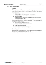
Energy can only be supplied to the gate driver if there is an AC voltage
on the primary side of the transformer mentioned above. This circuit is
safely disconnected by the safety relay. Correct function is ensured by
the positively-driven contacts.
DC/DC
Optokoppler
+5V int.
PLD
IGBT -Driver
PWM Generator
Modulator (DSP)
H- Bridge
Interface
+24V
OR
Main DSP
Controller
On / OFF
DC/DC
+24V int.
Sicherheits
-relais
Opto-
koppler
Interlock circuit
Signal circuit
Emergency
Stop circuit
Emergency stop
interface
1
2
3
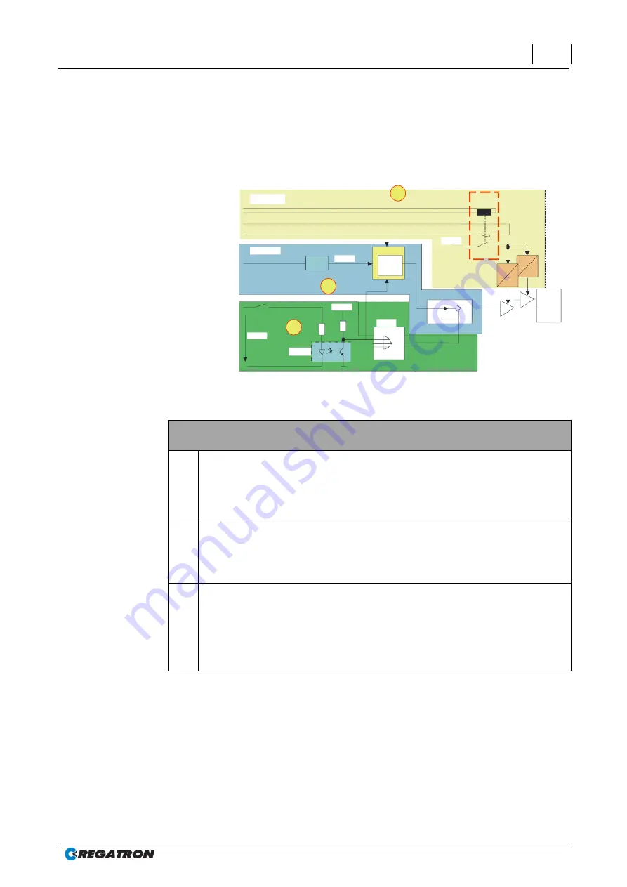
Fig. 50
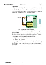
Overview of the internal signal flow
Internal signal flow
1
EMERGENCY STOP circuit
As described above, the gate driver supply is enabled and disconnected by an
externally controlled safety relay. A positively-driven contact is used for the
external monitoring of the correct function of the safety relay. The state of the
EMERGENCY STOP relay is also monitored by the main DSP.
2
Signal circuit
The start/stop command can come via the hardware interface or one of the
software interfaces. The main DSP processes this command and processes
all signals in the controller and sends the pulse pattern signal to the driver
input.
3
Interlock circuit
With the interlock circuit open, the opto-
coupler is not operated. The PLD’s
input signal is high. The PLD’s output is therefore always low (inverted OR
operator with other shutdown conditions). This low signal deactivates in the
hardware the modulator’s pulse pattern generator. As a consequence the
signal for operating the IGBT driver is inactive and the power stage (H-bridge)
shuts down.
Table 63
ISR internal signal flow.


