Manual - TC.P Quadro
TopControl application
2016-08-05
185/330
V04.52
6
Tab
– CONTROL (continued)
3
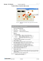
System control,
group
<VOLTAGE ON/OFF> button
<VOLTAGE ON>
On actuation
the label changes to VOLTAGE OFF
The power supply output provides power if there is a load.
“Voltage actual state” read-only indication changes to ON
(green).
<VOLTAGE OFF> On actuation the label changes to VOLTAGE ON.
The power supply output is electrically isolated.
“Voltage ac-
tual state” read-only indication changes to OFF (red).
<Clear errors> button
Actual errors are acknowledged, but are retained in the error history.
The reason for the error should be rectified first.
4
System status,
read-only indication of system state
RUN, READY, ERROR indication
Control input indicates the interface set in
-6-
.
For information on the Error and Warning indication as well as the
<Show Errordetail> and <Show Warndetail> buttons see Table 107, page
186.
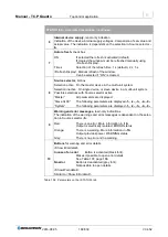
5
Autorefresh,
check box
The window is refreshed cyclically if the check box is selected.
Default: the check box is selected.
The times for refreshing the indication that can be selected:
1 s, 2 s, 5 s; default: 1 s
<Refresh display> button refreshes the window immediately.
6
Remote control input,
list box
The following interfaces for device remote control can be selected:
Analog inputs
For information on analogue remote programming
see chapter 3.3.3.2, page 74.
TC.HMI/RCU
For information on programming via HMI/RCU also in a mul-
ti-unit system see chapter 5.3.4, page 139.
RS-232/422
For information on programming via RS-232
e.g. using TopControl see chapter 3.2.4.9, page 67.
Internal references Only for use by the manufacturer!
7
Settings
<Store settings>
Settings made are written directly to the flash memory for
the TopCon power supply. The TopCon continues to use
these settings, even when the TopCon power supply is
switched on again.
<Edit VLS settings>
Opens the “Versatile limit switch” function.
For information on parameterisation via TopControl
see chapter 3.3.7.2, page 87.
8
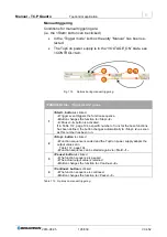
Controller indicator
The position of the red square indicates the active controller. I.e. whether the
device is in current, voltage or power limiting.
Red indication
Normal indication
Yellow indication
Only with sense function activated
For further information see chapter 3.2.4.4, page 55.
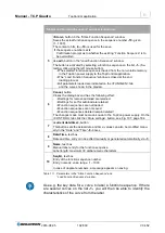
Table 106 Parameters on the <CONTROL> tab.


