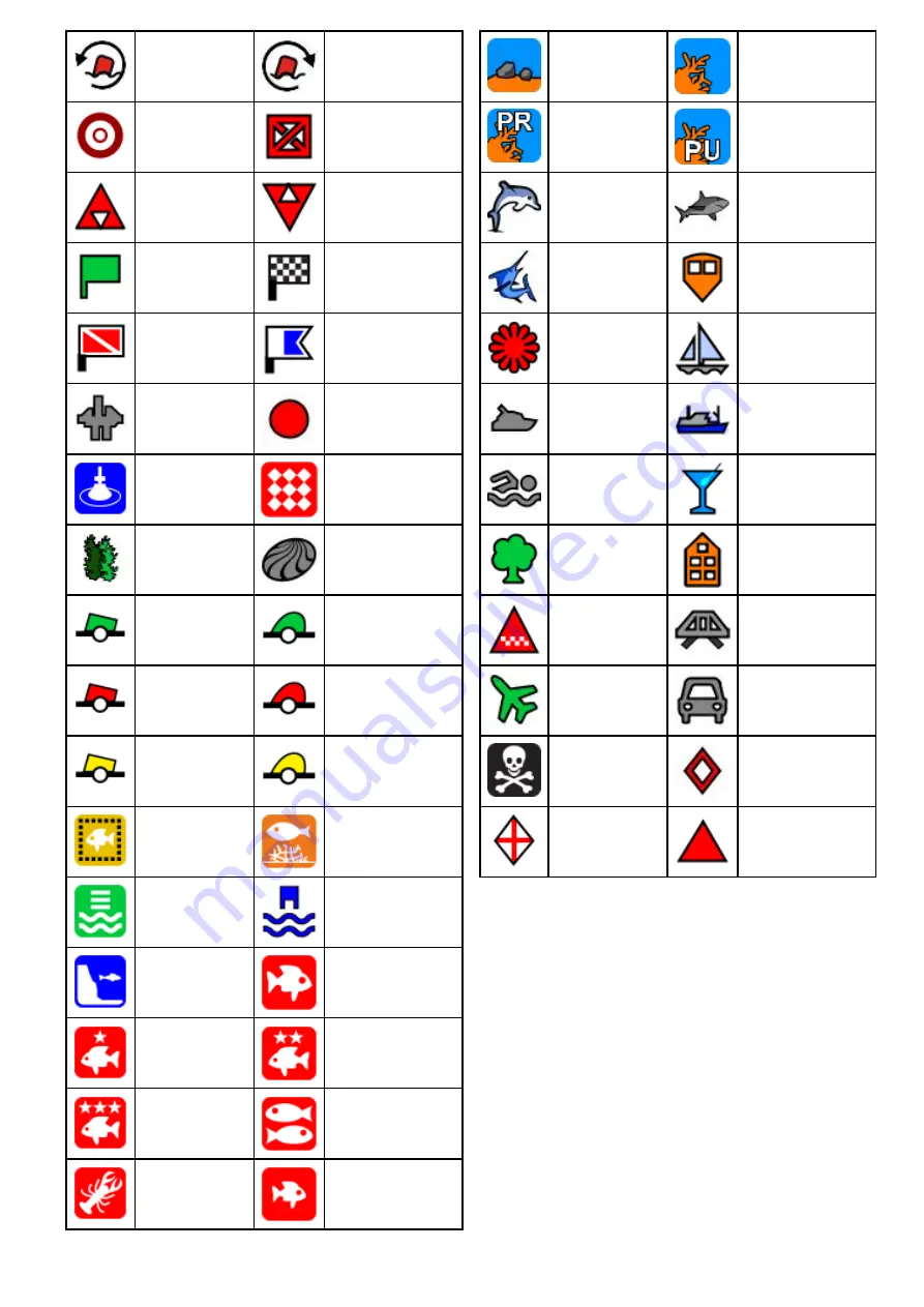
background image

Red racemark
anti-clockwise

Red Racemark
clockwise

Marker

Restriction

Bottom Mark

Top Mark

Route Start

Route End

Diver Down

Diver Down 2

Oil Rig

Filled Circle

FAD (Fish
Attracting
Device)

Concrete Rubble

Seaweed

Oyster

Green Can

Green Nun

Red Can

Red Nun

Yellow Can

Yellow Nun

Fish Trap

Brushpile

Preferred Marks

Post

Ledge

Fish

Fish 1 Star

Fish 2 Star

Fish 3 Star

School Fish

Lobster

Small Fish

Rocks

Reef

Private Reef

Public Reef

Dolphin

Shark

Billfish

Tank

Reef Ball

Sailboat

Sportsfisher

Trawler

Swimmer

Martini

Tree

Tower

Hill or Peak

Bridge

Airplane

Car

Skull

Diamond T

Diamond
Quarter

Filled Triangle

Showing and hiding waypoint groups

From the chart or radar application:
1. Select

WPT

.

2. Select

Display Wpts on: Chart

, or

Display

Wpts on: Radar

depending on the application

you have open.
The Show/Hide waypoints list is displayed.

Waypoints, Routes and Tracks

149

Summary of Contents for A65

Page 1: ...LightHouse TM multifunction display operation instructions English Date 05 2015 Document number 81360 1 EN 2015 Raymarine UK Limited Release 14...

Page 2: ......

Page 3: ...instructions Creating a Race Startline Using the Race Timer 14 16 Polar tables Added support for C Map by Jeppesen Easy Routing Chart application Automatic route generation Automatic route generation...

Page 4: ...uctions System 26 2 Power up troubleshooting 26 6 Sonar troubleshooting Trademark and patents notice Raymarine Tacktick Clear Pulse Truzoom HSB SeaTalk SeaTalkhs SeaTalkng Micronet Raytech Gear Up Mar...

Page 5: ...ngs 56 4 2 Save and restore items 58 4 3 Screenshots 60 4 4 Resetting your system 61 Chapter 5 Customizing your display 63 5 1 Language selection 64 5 2 Boat details 65 5 3 Units set up 66 5 4 Time an...

Page 6: ...nd distance 219 15 17 Waypoints in the Fishfinder application 220 15 18 Sensitivity settings 221 15 19 Fishfinder alarms 226 15 20 Frequency tuning 227 15 21 Sounder set up menu options 229 15 22 Tran...

Page 7: ...Chapter 23 Media player application 333 23 1 Media player connection 334 23 2 Enabling Bluetooth 334 23 3 Pairing a Bluetooth media player 335 23 4 Enabling audio control 335 23 5 Media player control...

Page 8: ...8 LightHouse multifunction display operation instructions...

Page 9: ...e therefore recommends that you do NOT use Automatic route generation to create any part of a route which will cross traffic lanes or pass near to traffic separation lines In these situations Automati...

Page 10: ...rs in such information may cause the product to malfunction Raymarine is not responsible for damages or injuries caused by your use or inability to use the product by the interaction of the product wi...

Page 11: ...nce IMO and SOLAS The equipment described within this document is intended for use on leisure marine boats and workboats NOT covered by International Maritime Organization IMO and Safety of Life at Se...

Page 12: ...12 LightHouse multifunction display operation instructions...

Page 13: ...n Chapter contents 2 1 Handbook information on page 14 2 2 Handbook conventions on page 15 2 3 Document illustrations on page 17 2 4 System feature highlights on page 18 2 5 HybridTouch overview on pa...

Page 14: ...n instructions 87247 eS Series installation instructions 87250 gS Series installation instructions 87248 LightHouseTM multifunction display operation instructions This document 81360 LightHouseTM New...

Page 15: ...ist or menu either by touch or physical buttons Touch Press your finger on the menu and slide up or down to scroll Physical buttons Turn the Rotary control clockwise or anti clockwise to scroll Applic...

Page 16: ...an onscreen icon WPT button c Series e Series eS Series RMK 9 keypad WPT icons a Series gS Series Throughout this manual the term Select WPT refers to pressing the physical WPT button or pressing the...

Page 17: ...and screenshots used in this document may differ slightly from your display model Unless otherwise stated Illustrations showing a multifunction display apply to all applicable multifunction display v...

Page 18: ...nner onscreen at the same time 16 1 Radar application overview and features 16 3 Multiple radar scanners Wireless video streaming and wireless MFD control via tablet or smartphone With the optional mo...

Page 19: ...control multiple thermal video cameras Your Sixth Sense at sea View the world around your vessel even in total darkness Thermal technology sees temperature not visible light This means that it sees t...

Page 20: ...akers Watch movies Watch television broadcasts such as the latest sporting event requires an external Satellite TV receiver Play videogames Playback video footage or view photos from an external digit...

Page 21: ...fuel manager Setting the low fuel alarm Enabling the fuel range ring Simulator Mode Simulator Mode enables you to practice using your display and familiarize yourself with its operation even when you...

Page 22: ...along with software versions and serial numbers Record live data streams from the data busses SeaTalkng NMEA 0183 etc for advanced diagnostics and for sending system information to Raymarine product s...

Page 23: ...unction displays which do not have physical buttons can be connected to a remote keypad which allows HybridTouch functionality All functions can be accessed using the touchscreen However there may be...

Page 24: ...24 LightHouse multifunction display operation instructions...

Page 25: ...only displays on page 33 3 12 Homescreen overview HybridTouch and non Touch displays on page 34 3 13 Pages on page 36 3 14 Applications on page 37 3 15 Splitscreen controls on page 38 3 16 Screen over...

Page 26: ...left in PowerSave mode for prolonged periods of time When switching off the power to your vessel ensure that the unit is powered off using the power button For more information on the amount of power...

Page 27: ...tions including all menu operations 2 Menu Accesses menus Press again to close menus 3 UniControl Provides a joystick rotary control and an OK push button for using menus and applications 4 Back Press...

Page 28: ...er controls for external devices Press and hold to switch the unit OFF 9 Card reader slot Open the card door to insert or remove a MicroSD card There are 2 card slots labelled 1 and 2 used for electro...

Page 29: ...owersave mode or access the power controls for external devices Press and hold to switch the unit OFF 9 Card reader slot Open the card door to insert or remove a MicroSD card There are 2 card slots la...

Page 30: ...press to return to a previous menu or dialog level 5 Range Out press to range out 6 Range In press to range in 7 Switch Active press to switch the active pane or to switch the active multifunction di...

Page 31: ...using physical buttons Locking the touchscreen HybridTouch displays On HybridTouch multifunction displays the Homescreen contains a dedicated Touch Lock icon With the homescreen displayed 1 Select th...

Page 32: ...ch means that the display is capable of recognizing multiple simultaneous touch inputs This means that you can use 2 or more fingers on the screen at the same time to perform multi touch gestures Pinc...

Page 33: ...hart VRM EBL VRM and EBL 1 or 2 Radar WIND Wind indicator Chart WPT Waypoint Chart Radar 3 11 Homescreen overview Touch only displays The Homescreen provides a central point of access for your display...

Page 34: ...pplication page A page can display multiple applications simultaneously 6 Status bar the status icons confirm the status of externally connected equipment including GPS AIS radar sonar and autopilot u...

Page 35: ...Timed Trans mit Scanner switches between on transmitting and standby mode Scanner goes into power save mode when constant use of radar is not required AIS status symbols AIS status is indicated by a...

Page 36: ...age The page last viewed is displayed after power up Choose page The page you select will be displayed after power up 4 If selecting Choose page the Homescreen is displayed 5 Select the icon for the p...

Page 37: ...e higher levels of detail and 3D views Fishfinder application with a transducer and a sonar variant multifunction display or compatible Sonar Module you can use the fishfinder application to help you...

Page 38: ...e active application and view it fullscreen by following the steps below With a page featuring multiple applications displayed 1 Touch anywhere inside the application you want to make active A border...

Page 39: ...ons can be used to switch the active application between full and splitscreen 3 Press the Back button or the Switch Active button to exit switch mode 3 16 Screen overview D12196 2 7 6 1 2 3 4 5 Screen...

Page 40: ...aypoints and routes D12277 2 1 4 5 2 3 Screen item Description 1 Back Displays with a touchscreen Select the onscreen Back icon to go back to the previous menu Non touchscreen or HybridTouch displays...

Page 41: ...or characters that have multiple available accents use the character key to toggle between them 4 Select the key to enter the character Numeric menu items Numeric menu items display numeric data and e...

Page 42: ...ard is displayed The wizard guides you through the following basic configuration settings 1 Language 2 Boat type 3 Configure Units Units of measure 4 Boat Details Note These settings can also be set a...

Page 43: ...t Minimum safe beam is required when using Jeppesen Easy Routing Minimum Safe Beam can be established by adding together Maximum Vessel Width Beam Safety Margin an adequate clearance to either side of...

Page 44: ...Time Format and Local Time UTC menu items to set your time and date preferences Data master Any system containing more than one networked multifunction display must have a designated data master The d...

Page 45: ...racy of between 5 and 15 m As an example assuming a receiver error of 5 m an HDOP of 2 would represent an error of approximately 15 m Please remember that even a very low HDOP figure is NO guarantee t...

Page 46: ...arine GPS receivers and GNSS receivers Oper ational SBAS MSAS All internal and external Raymarine GPS receivers and GNSS receivers Oper ational SBAS GAGAN All internal and external Raymarine GPS recei...

Page 47: ...ter A list of available filter levels is displayed Low Medium default High 2 Select the require filter level from the list Restarting the GNSS GPS GLONASS receiver To restart the GNSS GPS GLONASS rece...

Page 48: ...Using the engine identification wizard information Make the data connections according to the instructions provided in the 87202 ECI Installation instructions Ensure all data buses are powered up inc...

Page 49: ...ternal Devices Engines Set up 2 If required change the number of engines your vessel has by selecting Num of Engines and entering the correct number of engines You can select up to 5 engines 3 Select...

Page 50: ...to the following devices MFDs networked using SeaTalkhs MFDs networked using SeaTalkng SeaTalkng instruments displays networked using SeaTalkng SeaTalk instruments displays networked via a SeaTalk to...

Page 51: ...ent chart data you can insert compatible chart cards into the unit s memory card reader Use branded chart cards and memory cards When archiving data or creating an electronic chart card Raymarine reco...

Page 52: ...an be used to check and update the software of compatible Raymarine products You can identify product software versions using the Diagnostics page on your MFD Homescreen Set up Maintenance Diagnostics...

Page 53: ...v2 16 v2 18 Estimat ed time approx 9 mins D13270 1 2 4 6 1 3 5 1 No software update available on memory card 2 Software update available on memory card 3 Software on memory card is older than the sof...

Page 54: ...courses to help you make the most of your products Visit the Training section of the Raymarine website for more information http www raymarine co uk view id 2372 FAQs and Knowledge Base Raymarine has...

Page 55: ...aging display data Chapter contents 4 1 Saving user data and user settings on page 56 4 2 Save and restore items on page 58 4 3 Screenshots on page 60 4 4 Resetting your system on page 61 Managing dis...

Page 56: ...you want to save data to if your display only has 1 card slot then you will not be prompted 8 Select SD1 for a memory card in the top card slot or SD2 for a memory card in the bottom card slot A conf...

Page 57: ...porting waypoints routes or tracks from a memory card With the Homescreen displayed 1 Ensure you have a memory card containing the user data in gpx format in one of the card slots 2 Select My Data 3 S...

Page 58: ...splay only has 1 card slot then you will not be prompted 5 Select SD1 for a memory card in the top card slot or SD2 for a memory card in the bottom card slot A confirmation dialog is displayed 6 Selec...

Page 59: ...mmunity edits Chart text Chart boundaries Boat size Databox 1 Databox 1 content Databox 2 Menu Setting Databox 2 content Presentation Vectors Vector length Vector width Presentation Objects Show rocks...

Page 60: ...has a Back button you can also take a screenshot by pressing and holding the Back button until the confirmation message appears Selecting the SD card slot for screenshots If your multifunction displa...

Page 61: ...a Resetting system settings With the homescreen displayed 1 Select Set up 2 Select Maintenance 3 Select System Settings Reset A message is displayed prompting you to confirm the action 4 Select Yes to...

Page 62: ...62 LightHouse multifunction display operation instructions...

Page 63: ...page 64 5 2 Boat details on page 65 5 3 Units set up on page 66 5 4 Time and Date set up on page 67 5 5 Display preferences on page 68 5 6 Databar and databox overview on page 70 5 7 List of data ite...

Page 64: ...tuguese Brazilian Russian Slovenian Spanish Swedish Turkish With the Homescreen displayed 1 Select Customize 2 Select Language 3 Select your language from the list of languages Language is part of the...

Page 65: ...y Routing feature Depth measurement Min Safe Beam The Minimum Safe Beam setting is required when building routes using the Easy Routing feature Beam measurement Min Safe Height The Minimum Safe Height...

Page 66: ...values related to temperature Fahrenheit Celsius Pressure Units The units of measure that will be used in all applications for the display of all values related to pressure Bar PSI Kilopascals Volume...

Page 67: ...te information in all applications MM DD YY Month Day Year DD MM YY Day Month Year Time Format Allows you to specify the preferred format for the display of time information in all applications 12hr 2...

Page 68: ...nd range out icons Note Onscreen range controls are not available on non touchscreen displays Onscreen range controls cannot be hidden on touch only displays Show default Hide Chart Touch Call outs To...

Page 69: ...htness function see list of compatible units above Before a unit can respond to a shared brightness adjustment it must be assigned to the relevant Brightness Group A single unit can only belong to one...

Page 70: ...e the databar On multifunction displays that have a touchscreen the databar that is displayed at the top of all applications pages can be set to auto hide This provides a larger screen area for the ap...

Page 71: ...the cell For example Depth data 6 Select the data item The data you selected is displayed on screen in the appropriate cell 7 Select Home or Back when completed Displaying status icons in the databar...

Page 72: ...s Battery Amps Battery Temperature Battery Voltage Battery Battery status Battery Charge Rate of Turn Heel Angle Boat Types of data generated by your vessel For example tank levels Trim Tabs Data appl...

Page 73: ...Pressure Oil Pressure Coolant Temperature Transmission Oil Temperature Transmission Oil Pressure Transmission Gear Boost Pressure Fuel Pressure Fuel Flow Rate Fuel Flow Inst Fuel Flow Avg Engine Hours...

Page 74: ...Fuel Types of data related to the fuel system For example fuel levels Fuel Used Season Pressure Air Temperature Minimum Air Temperature Maximum Air Temperature Drift Set Set Drift Apparent Wind Chill...

Page 75: ...only Locked Heading Locked Heading Error LH Error and LH Data application only Tack Heading Heading Heading related data For example locked heading Compass Data application only Cursor Position Only...

Page 76: ...G CMG VMG Data application only Distance to Waypoint Distance Made Good Waypoint ETA Waypoint TTG Route ETA Route TTG Pilot Pilot related data For example rudder Rudder Angle Speed Maximum Speed Avera...

Page 77: ...Well Local Time Time Time related data For example local time Local Date AWA Maximum AWA Minimum AWA AWS Maximum AWS Minimum AWS TWA Maximum TWA Minimum TWA TWS Maximum TWS Minimum TWS TWD Cardinal W...

Page 78: ...representations are only available from the Data application Databar and data cell overlays can only display digital items Note The Battery Engine Fuel and Tanks menus will display 1 set of data item...

Page 79: ...plays the Pilot Control dialog Only available when a Raymarine autopilot is detected on the system and Autopilot Control is set to On Pilot Response Enables selection of the pilot response level when...

Page 80: ...to the External devices menu section of the manual Wireless Connections Provides access to the Wi Fi and bluetooth connection options Refer to the Wireless connections menu section of the manual Menu...

Page 81: ...satellite fix can be acquired D Fix A differential beacon fix has been acquired SD Fix A differential satellite fix has been acquired Position Displays the latitude and longitude position of your rece...

Page 82: ...stem choosing a source of data that you do not want to use Device selection Menu item Description GPS Enables you to search for any externally connected GPS devices and select the one you want to use...

Page 83: ...s menu item is only available when an AIS unit is detected or when Simulator mode is On For an explanation of these options refer to the AIS menu options described in the AIS section of this document...

Page 84: ...an encrypted connection If you want to prevent unauthorized devices from connecting to your display you must specify the same SSID for both the multifunction display and the wireless device you want t...

Page 85: ...Menu item Description Options Viewing only RayView Remote Control RayRemote or RayControl Remote Control Customizing your display 85...

Page 86: ...rom the external heading sensor On Off default NMEA Output Settings Allows you to enable or disable the individual NMEA sentences that are sent by the multifunction display to any devices connected th...

Page 87: ...ot the datum used by your paper charts you can change the datum used by your multifunction display When you change the datum for your multifunction display the chart grid will subsequently move accord...

Page 88: ...system containing more than one networked multifunction display must have a designated data master The data master is the display which serves as a primary source of data for all displays it also hand...

Page 89: ...Software Sirius If connected to a Sirius weather receiver this option enables you to view Sirius weather statistics Save Logs Allows you to save error logs to a MicroSD card for troubleshooting purpos...

Page 90: ...90 LightHouse multifunction display operation instructions...

Page 91: ...Chapter 6 Document viewer application Chapter contents 6 1 Document viewer overview on page 92 Document viewer application 91...

Page 92: ...document to fit the width of the application window Close File Closes the open document Opening the user manual The product user manual is stored on the internal memory From the homescreen 1 Select D...

Page 93: ...ge the zoom factor Selecting a page You can skip to the page you want to view by entering the page number With a pdf document open 1 Select Menu 2 Select Go to page The numeric keypad is displayed 3 E...

Page 94: ...the normal viewing Keyword not found The document viewer will let you know if the keyword you have searched for does not appear in the document If the keyword is not found then the find tool bar will...

Page 95: ...the current locked heading on page 97 7 5 Disengaging the autopilot on page 98 7 6 Manually displaying the pilot control dialog box on page 99 7 7 Pilot Control dialog on page 99 7 8 Pilot Bar on page...

Page 96: ...e autopilot alarms 7 13 Autopilot alarms Note In a system that does not include a dedicated Pilot control head the Data Master MFD cannot be switched Off or put into PowerSave mode whilst the autopilo...

Page 97: ...te Goto Cursor Goto Waypoint or Follow Route as appropriate The Pilot Control dialog is displayed 2 Select Yes Track Engaging the autopilot using the context menu You can engage the autopilot in track...

Page 98: ...and the Pilot Control dialog is displayed Disengaging the autopilot using the pilot button On multifunction displays which have a dedicated pilot button or when using a remote keypad you can disengag...

Page 99: ...ng Pilot Control dialog Auto The example below shows the Pilot Control dialog options when Auto locked heading has been engaged D12882 1 1 2 3 4 5 6 8 7 Description 1 Pilot Status Current pilot mode 2...

Page 100: ...the context menu 6 When you are following a route or going to a waypoint or cursor position and select Menu Navigate Stop Goto Stop Follow or Advance Waypoint 7 When you arrive at a target waypoint No...

Page 101: ...Pilot settings include the following options Vessel Settings Drive Settings Sail Boat Settings Commissioning Initial setup and commissioning Vessel settings The vessel settings are designed to provide...

Page 102: ...2 Check the autopilot heading on your multifunction display 3 From the Pilot Set up page select Pilot Settings 4 Select Vessel Settings 5 Select Compass Offset 6 Adjust the Compass Offset so that the...

Page 103: ...ansducer Note To perform this procedure it is desirable to have a networked device such as an instrument pilot control head or multifunction display that can display the current rudder position onscre...

Page 104: ...ance with the associated Installation instructions Check also that the commissioning engineer is familiar with the installation and components of the autopilot system including Vessel type Vessel stee...

Page 105: ...ard ensure the pilot is in standby mode and then from the Pilot Set up page 1 Select Pilot Settings 2 Select Commissioning 3 Select Dockside Wizard Selecting a drive type Drive type selection is avail...

Page 106: ...e On vessels without a rudder reference transducer it is important to set the hard over time limits correctly to ensure accurate autopilot operation Hard over time is the time it takes the vessel s st...

Page 107: ...compass offset value using the pilot control head or multifunction display and fine tune the heading to an accurate value Note Do NOT rely on the heading accuracy until you are satisfied that compass...

Page 108: ...ifunction display provides an audible alarm sound providing that the alarm has not already been silenced The Pilot Control dialog is displayed indicating a new alarm Additionally the autopilot status...

Page 109: ...Chapter 8 Alarm management Chapter contents 8 1 Alarms overview on page 110 8 2 Alarm Manager overview on page 110 8 3 Alarm options on page 113 Alarm management 109...

Page 110: ...arm message is displayed 1 Select Ok The message is dismissed and the alarm tone is stopped Tip If an alarm message includes an Edit button then the alarm s settings can be accessed directly from the...

Page 111: ...t the Settings tab 2 Select the alarm category for the alarm you want to enable disable Alarms are displayed in the Alarm Manager in the following categories Safety Alarms General Alarms Switch Panel...

Page 112: ...nit of measure for the alarm threshold you are currently changing by selecting on the relevant unit of measure from the numeric keypad Clearing the alarm history You can view the history of alarm even...

Page 113: ...d during active navigation an alarm is triggered when your vessel steers off track more than the value you specify for the Off Track XTE setting Enable Enabled Ticked Disabled Un ticked default Off Tr...

Page 114: ...until the Fuel Manager is enabled Note You cannot set LFR to be more than the current TFC value Enable Enabled Ticked Disabled Un ticked default Fuel level Default value If Total Fuel Capacity TFC ha...

Page 115: ...connected sonar module Fishing deep water arrival When enabled an alarm is triggered when the depth reaches the value specified in the Deep Limit alarm setting This option is only available when curre...

Page 116: ...ft 0 3 fa default Range 0 6 m to Fish alarm deep limit 2 ft to Fish alarm deep limit 0 3 fa to Fish alarm deep limit Fish alarm deep limit Default values 305 m 1 000 ft 167 fa Range Fish alarm shallo...

Page 117: ...er specific error message Unknown error 2 manufacturer specific error message Unknown error 3 manufacturer specific error message Unknown error 4 manufacturer specific error message Unknown error 5 ma...

Page 118: ...118 LightHouse multifunction display operation instructions...

Page 119: ...Chapter 9 Man Overboard MOB Chapter contents 9 1 Man overboard on page 120 Man Overboard MOB 119...

Page 120: ...sting navigation function is cancelled If position or heading and speed information is available a MOB waypoint is placed at the current vessel position in any application that is capable of showing w...

Page 121: ...n for 4 seconds The MOB alarm is cancelled and normal operation is resumed Cancelling the man overboard MOB alarm On a multifunction display with physical buttons or when using a remote keypad you can...

Page 122: ...122 LightHouse multifunction display operation instructions...

Page 123: ...Chapter 10 DSC VHF radio integration Chapter contents 10 1 DSC VHF radio integration on page 124 10 2 Enabling DSC VHF radio integration on page 124 DSC VHF radio integration 123...

Page 124: ...message place a waypoint on the chart at the GPS position of the distressed vessel or immediately start navigating Goto Vessel to the GPS position of the distressed vessel Position Data the Position...

Page 125: ...Chapter 11 Fuel manager Chapter contents 11 1 Fuel manager overview on page 126 Fuel manager 125...

Page 126: ...full Log each subsequent fuel fill whether partial or full Note Fuel manager estimates the amount of fuel onboard based on the user logging each time you fill up the total fuel capacity and how much f...

Page 127: ...is highlighted Selecting Low Fuel will turn the low fuel alarm On or Off 5 Select Fuel Level The fuel level numeric adjust control is displayed 6 Adjust the fuel level to the required value The low fu...

Page 128: ...n 3 Select Overlays 4 Select Fuel Range Ring so that On is selected The fuel range ring pop up message is displayed 5 Select OK to turn on the fuel range rings 128 LightHouse multifunction display ope...

Page 129: ...S vectors on page 132 12 6 AIS status symbols on page 133 12 7 AIS silent mode on page 133 12 8 AIS target symbols on page 134 12 9 Displaying detailed AIS target information on page 135 12 10 Viewing...

Page 130: ...ce it will travel over a specified period of time COG SOG vector Targets displayed with their vectors are referred to as active targets and are scaled according to the size of the vessel The larger th...

Page 131: ...n display using NMEA0183 or SeaTalkng depending on the AIS unit If connecting using NMEA0183 you will now need to specify the 38 400 baud setting homescreen Set up System Settings NMEA Set up for the...

Page 132: ...the list From the Display AIS Targets menu you can switch on All AIS targets only Dangerous AIS targets or switch AIS targets Off 12 5 Displaying AIS vectors You must have the correct data available b...

Page 133: ...data to other AIS receivers but still wish to receive data from other vessels Note Not all AIS equipment supports silent mode For more information refer to the documentation that accompanies your AIS...

Page 134: ...n Lost target When the signal of a dangerous target not received for 20 seconds Target in latest predicted position Alarms sounds if enabled Target flashes Buddy target Target has previously been adde...

Page 135: ...th only the AIS overlay enabled go to Menu AIS Options Targets View AIS List From the Chart application when the Radar overlay is also enabled go to Menu Radar AIS Options Targets View Targets Lists V...

Page 136: ...Goto Waypoint Note You will NOT receive any safety messages in Simulator mode homescreen Set up System Settings Simulator Showing the Safe Zone Ring in the Chart application To show the Safe Zone ring...

Page 137: ...vector lines displayed depends on the distance that an AIS target travels in the time period that you specify for this setting 0 5 min 1 min 3 min 6 min 12 min 30 min 60 min Target History Targets pr...

Page 138: ...you to add AIS equipped friends and regular contacts to a Buddy List on your multifunction display As soon as a vessel on your Buddy List sails into the range of your AIS unit the vessel icon changes...

Page 139: ...a buddy s details From the chart or radar application 1 Select the AIS buddy target The AIS buddy context menu is displayed 2 Select View Buddy List 3 Select the buddy you wish to edit The Buddy opti...

Page 140: ...140 LightHouse multifunction display operation instructions...

Page 141: ...acks Chapter contents 13 1 Waypoints overview on page 142 13 2 Routes on page 150 13 3 Tracks on page 160 13 4 Import and Export on page 162 13 5 Waypoints routes and tracks storage capacity on page 1...

Page 142: ...waypoints are shown An active waypoint is the one that you are navigating to D11759 3 2 1 3 1 Inactive waypoint 2 Active waypoint 3 Alternate waypoint symbols The default waypoint symbol is a red X Al...

Page 143: ...The context menu is displayed 2 Select Place Waypoint The Waypoint Saved dialog is displayed 3 Select the Symbol field to change the symbol that will be used to display the waypoint in the Chart or Ra...

Page 144: ...are organized into groups By default all waypoints are placed in the UNSORTED group New waypoint groups can be created and each waypoint can be assigned to a waypoint group For example you could crea...

Page 145: ...ymbol that you want to use for the waypoints in the selected group A confirmation dialog is displayed 4 Select Yes to apply the new symbols to the waypoints or select No to cancel Moving a waypoint to...

Page 146: ...played Note The waypoint list can also be accessed directly from the Homescreen by selecting WPT or by going to the My Data menu and selecting Waypoint List Editing waypoint details With the Waypoint...

Page 147: ...sting or new waypoint group or assign all of the waypoints the same waypoint symbol Searching for waypoints by name or keyword Waypoints can be searched for by name or keyword From the Waypoints list...

Page 148: ...is drawn in the wrong place you can draw a new area by selecting 2 new corner points 8 Select Search from the menu A list of all waypoints in the selected area is displayed 9 Select Erase Wpts to era...

Page 149: ...1 Star Fish 2 Star Fish 3 Star School Fish Lobster Small Fish Rocks Reef Private Reef Public Reef Dolphin Shark Billfish Tank Reef Ball Sailboat Sportsfisher Trawler Swimmer Martini Tree Tower Hill o...

Page 150: ...a line D11750 1 Route features There are a range of route features for building navigating and managing routes The route features allow you to Build and save a route for use when required stored in th...

Page 151: ...the route or 10 Select Edit to change the route name or change the route color or 11 Select Exit to save the route and return to the chart application Note If you place a waypoint at the wrong positi...

Page 152: ...Yellow racemark anti clockwise Yellow Racemark clockwise Red racemark anti clockwise Red Racemark clockwise Adjusting chart range while building a route From the Build Route menu 1 Use the on screen R...

Page 153: ...neration can only be used when generating routes within the area covered by your compatible cartography Automatic route generation can be used between waypoints less than 100 nm apart Automatic route...

Page 154: ...HAT In both cases the tide can be higher than the datum due to atmospheric effects such as high air pressure wind direction etc Caution Easy Routing Dredged areas The Jeppesen Easy Routing feature wil...

Page 155: ...g the generated route Important Do not rely on automatic route generation alone to guarantee that the route is safe to navigate Review the suggested route carefully and if necessary edit the route bef...

Page 156: ...ation will NOT be used when moving waypoints within routes extra care should be taken to ensure that the route leg and any moved waypoints are safe to navigate 4 Scroll over the entire route to identi...

Page 157: ...ues specified in the Boat Details settings The start and end waypoints will be created and joined with a straight route leg however there will be no automatically generated waypoints and the waypoint...

Page 158: ...e to review or edit 1 Do one of the following to select the required route From the chart application select a route on screen to display the route context menu From the chart application select Menu...

Page 159: ...m system dialog is displayed 5 Select Erase All The confirm delete dialog is displayed 6 Select Yes to confirm or No to cancel the action Route context menu Placing the cursor over a route in the char...

Page 160: ...tance Track Interval specifies the interval value e g 15 minutes For example when creating a track for a long journey an interval set to Auto could result in rapid use of all of the storage available...

Page 161: ...erase 3 Select Erase Track The erase track pop up message is displayed 4 Select Yes to confirm or No to cancel the action Erasing all tracks From the Homescreen 1 Select My Data 2 Select Import Export...

Page 162: ...ettings 13 5 Waypoints routes and tracks storage capacity The display can store the following quantities of waypoints routes and tracks Way points 3000 waypoints 100 waypoint groups each group can con...

Page 163: ...on the chart display on page 173 14 9 Chart Orientation on page 174 14 10 Chart motion mode on page 175 14 11 Chart views on page 176 14 12 Chart display on page 178 14 13 Overlays on page 179 14 14 C...

Page 164: ...and bearings Alter the Chart application s orientation to better suit your needs 14 9 Chart Orientation Change offset the vessel position in the Chart application 14 10 Chart motion mode Chart applic...

Page 165: ...an area onscreen displays a Call out which provides information about the selected location or object Call outs are enabled by default and can be disabled from the Homescreen Homescreen Customize Dis...

Page 166: ...d regions from around the globe Refer to the Raymarine website www raymarine com for the latest information on available LightHouse charts Raster charts Raster charts are an exact copy scan of an exis...

Page 167: ...n be resumed rather than downloading the entire file again 9 Wait for the download to finish The downloaded file can now be unzipped extracted to memory card for use with your multifunction display Un...

Page 168: ...y The following Navionics cartography types are available for your multifunction display Ready to Navigate Silver Gold Gold Platinum Platinum Fish N Chip Hotmaps To check the current availability of N...

Page 169: ...Chart ranging and panning Ranging in and out The table below shows the Range controls available for each display variant Rotary Control eS Series Rotary Control c Series e Series RMK 9 keypad Range i...

Page 170: ...o a waypoint stored on the system Stop Goto Stops the Goto Cursor or Goto Waypoint Stop Follow Stops following the current route Restart XTE Restarts the Cross Track Error Advance Waypoint When follow...

Page 171: ...igating a route then the next waypoint is selected Note You can set the radius distance of the waypoint arrival circle which is used to trigger the waypoint arrival alarm Changing destination during a...

Page 172: ...in the route 14 7 Race Startline and Race Timer Creating a Race Startline A Race Startline can be created by placing port and starboard end points in the Chart application The end points can be create...

Page 173: ...d 1 Touch the Race Timer to start the countdown 2 With the timer running you can select the Race Timer to synchronize 3 Touch and hold the Race Timer to stop and reset the countdown 14 8 Vessel positi...

Page 174: ...avigation Note To prevent continuous backwards and forwards rotations as the vessel yaws from side to side the chart will not update unless the heading changes by at least 10 degrees from the last dis...

Page 175: ...moves relative to your vessel You can use the Menu Presentation View Motion Boat Position menu options to determine whether the vessel is fixed in the center of the window or offset If you change the...

Page 176: ...around the chart area 11 Target waypoint current target waypoint 12 Databoxes used to display data such as depth on the chart screen Item Description 13 AIS target a vessel broadcasting AIS informati...

Page 177: ...low From the Chart application menu 1 Select Presentation 2 Select View Motion 3 Select 3D Display Options 4 Select Center of View so that On is highlighted Selecting centre of view will switch the cr...

Page 178: ...e level of detail that is displayed on screen The Chart display menu option is only available when using vector based cartography The Chart display options are shown below Simple Detailed Extra Detail...

Page 179: ...lay is not available in 3D view 2D Shading Determines whether terrain shading is displayed in 2D view Community Edits Determines whether the community layer is enabled or disabled Chart Text Determine...

Page 180: ...L COG is displayed in the top left corner of the Chart application Note When the overlay is using COG misalignment of the Radar and Chart images can occur due to tide and current effects Enabling Rada...

Page 181: ...a The chart display is redrawn showing the new overlay selection NOWRad weather overlay With a suitable weather receiver connected to your multifunction display you can overlay NOWRad weather informat...

Page 182: ...id so that On is selected to turn the grid on or 4 Select Chart Grid so that Off is selected to turn the grid off 2D shading If supported by your cartography type you can switch shading of land and se...

Page 183: ...text Off The default setting for Chart text is On Switching chart text on and off The Chart text can be switched on and off by following the steps below From the Chart application menu 1 Select Prese...

Page 184: ...the zone ring between hidden to visible Setting up the Safe Zone Ring You can adjust the Safe Zone Ring radius the time to Safe Zone and choose whether AIS targets trigger the Safe Zone alarm from th...

Page 185: ...Fuel Range Ring so that Off is selected Changing the size of the vessel symbol The vessel symbol size can be changed following the steps below From the Chart application menu 1 Select Presentation 2...

Page 186: ...nly shown when the Boat Type setting is set to a sailing vessel Vector length The length of the Heading and COG vector lines can be set to the distance your vessel will travel in the time you specify...

Page 187: ...option shows the current course on the opposite tack Fixed Angles the vectors are created based on specified Upwind and Downwind angles These angles are set by default to 45 and 165 respectively and c...

Page 188: ...5 65 120 165 2 5 5 0 7 0 x x y 0 1 6 2 1 4 1 5 0 5 3 6 1 2 1 5 1 6 4 1 0 2 6 3 7 0 0 0 y D13324 1 2 3 1 1 Increasing TWS values in knots 2 Increasing TWA values in degrees 3 Target vessel speed values...

Page 189: ...il disables the following objects and overlays 2D Shading Community Edits Chart Text Chart Boundaries Light Sectors Routing Systems Caution Areas Marine Features Land Features Panoramic Photo Roads Ad...

Page 190: ...mbols are used International or US These symbols correspond to paper charts Light Sectors Determines whether the sector of light cast by a fixed beacon is displayed Routing Systems Determines whether...

Page 191: ...ect on screen and choose Chart Objects from the chart context menu to view information about the selected object Select Find Nearest from the chart context menu to search for objects close by Displayi...

Page 192: ...nics animated currents Example current animation Arrows are used to indicate the direction of current flow The length of the arrow indicates the flow rate and the color of the arrow indicates flow spe...

Page 193: ...electronic charts may allow animation of the tide information tide stations Animated tide information is available in the chart application wherever a diamond shaped symbol with a T is displayed This...

Page 194: ...when nightfall occurs 6 Low High Tide Indicates the time at which low or high tide occurs 7 Date navigation Use the icons to move to the next or previous day 8 Time The horizontal axis of the graph i...

Page 195: ...termines the depth at which the Safety contour is displayed The Safety contour cannot be set to a value less than the Shallow contour or higher than the Deep contour Deep Water From Determines the dep...

Page 196: ...c in the chart application title bar Any changes made to the heading range or position in any chart instance will be reflected in all other chart instances Note When the 2D and 3D chart views are sync...

Page 197: ...nd Off 6 Select Back or Ok to close the measure menu leaving the current measurement on screen Measuring from point to point From the chart application 1 Select the location on screen that you want to...

Page 198: ...198 LightHouse multifunction display operation instructions...

Page 199: ...e 212 15 10 Depth Range on page 213 15 11 SideVisionTM Range on page 214 15 12 Fishfinder scrolling on page 215 15 13 Fishfinder display modes on page 215 15 14 SideVisionTM Views on page 217 15 15 Pr...

Page 200: ...ottom detection even through bait balls and thermoclines and detection sensitivity D12601 2 CHIRP Sonar overview CHIRP sonar produces a conical shaped beam the coverage of the conical beam is the wate...

Page 201: ...on the sea floor bridge piers wrecks shoals or fish SideVision produces two wide angle side to side beams each with a thin fore to aft beam The coverage of the SideVision beams is a swath on each sid...

Page 202: ...ey hit the sea floor The water column close to your vessel is displayed as a dark band in the image The abrupt change to a lighter section in the image indicates where the sea floor is first detected...

Page 203: ...m and back The returning echoes are affected by bottom structure and by any other objects in their path for example reefs wrecks shoals or fish The Sonar module interprets these signals and builds up...

Page 204: ...window includes the following features The bottom together with any bottom structure such as reefs and shipwrecks etc Target images indicating fish A status bar indicating the current sonar module an...

Page 205: ...nternal sonar module All variants allow you to connect a compatible external sonar module or use an internal sonar module from a networked display The sonar channel you want to use must be selected fr...

Page 206: ...Depths are measured from the transducer to the sea bed but you can apply an offset value to the depth data so that the displayed depth reading represents the depth to the sea bed from either the keel...

Page 207: ...moderately wide sonar beam 160 kHz Gives good detail in shallow waters 200 kHz Gives the best detail in shallow waters Low CHIRP Good target separation in deep water Channel Descrip tion CHIRP externa...

Page 208: ...st of available channels for the selected sonar module is displayed 4 Select a channel from the list The Channel selection page will close and the Fishfinder application will now show the selected cha...

Page 209: ...osstalk interference between the left and right receiving channels in areas of strong target returns Examples of strong target returns include solid objects such as underwater bridge structure This in...

Page 210: ...Settings Power Mode Note that the Power Mode setting is not available for all transducers Ensure that you have a common RF ground point for all electrical equipment on your vessel On vessels without a...

Page 211: ...or 4 using non touch controls select the channel and then press and hold the Ok button until the options screen is displayed 5 Select Copy Channel The on screen keyboard is displayed 6 Enter the name...

Page 212: ...scription 1 A hard bottom sand produces a thin line 2 A soft bottom mud or seaweed cover produces a wide line 3 A rocky or uneven bottom or a wreck produces an irregular image with peaks and troughs T...

Page 213: ...nual and adjust the range to the known charted depth of your location 4 Once bottom has been regained you can switch range mode back to Auto 15 10 Depth Range The Depth Range function enables you to d...

Page 214: ...shift dialog 15 11 SideVisionTM Range The SideVisionTM Range function enables you to define the distance to the left and right of the vessel that is displayed on screen The range displayed on screen c...

Page 215: ...o that Pause is highlighted Selecting Scrolling again will resume the scrolling 15 13 Fishfinder display modes Selecting a display mode for the Fishfinder application When using a Legacy Traditional C...

Page 216: ...han historical image of the seabed and fish directly below your vessel The standard fishfinder display shows a historical record of fishfinder echoes If required you can display a live image of the bo...

Page 217: ...etting to the required value 9 Select Back or use the Ok button to confirm the setting 15 14 SideVisionTM Views When connected to a SideVisionTM sonar module the default view displays both Left port a...

Page 218: ...n options Menu Item Description Options Target Depth ID Controls whether the depth of identified targets are displayed The level of targets displayed is directly linked to the level of Fish Alarm sens...

Page 219: ...ed against recognized targets The sensitivity of these IDs is directly linked to the Fish Alarm sensitivity the greater the fish alarm sensitivity the greater the number of labelled targets 3 Depth li...

Page 220: ...menu is displayed 2 Select Place Waypoint Placing a waypoint using the WPT button or icon From the fishfinder application 1 Select WPT The waypoint menu is displayed 2 Whilst the waypoint menu is open...

Page 221: ...onar module automatically adjusts the gain setting to suit current conditions Auto Gain modes When connected to a Legacy sonar module or a Traditional internal sonar module 3 Auto Gain modes are avail...

Page 222: ...nabled Setting auto gain mode using the menu When using a Legacy sonar module or a Traditional internal sonar module 3 Auto Gain modes are available The Auto Gain mode can be set by following the step...

Page 223: ...lue 5 Select Back to confirm setting and close slider bar or 6 Select Auto to enable automatic Color gain control Contrast DownVisionTM and SideVisionTM use monochrome shading to determine the strengt...

Page 224: ...portion of the sonar beam Top out mode is active when TVG values are between 0 and 30 TVG values between 31 and 100 represent actual TVG control 0 TVG 30 TVG Setting TVG to Automatic The TVG setting...

Page 225: ...er reduces the amount of clutter displayed onscreen by varying the gain throughout the column of water Adjusting the setting can improve target identification however for optimum performance in most c...

Page 226: ...ds when the detected depth is greater than the deep limit Fishfinder Shallow alarm sounds when the detected depth is less than the shallow limit Setting up fish alarms From the Alarms menu homescreen...

Page 227: ...as the system will set the frequency automatically to suit your transducer s operating conditions Lower frequencies e g 50 kHz Produces a wide sonar beam and penetrate the water well Lower frequencies...

Page 228: ...HIRP sonar module will sweep the transducer s available frequency range in each ping With the CHIRP sonar module set to a non CHIRP mode the frequency can be fine tuned to adjust the frequency at whic...

Page 229: ...ngs per second CHIRP and traditional external sonars 5 to 30 pings per second Ping Enable The sonar ping can be disabled This is useful when other equipment is being tested or if someone is diving ben...

Page 230: ...e dependent on the sonar module connected Speed Transducer Select the appropriate speed transducer from those available This option is only available if you are not using a combined Depth Speed or Dep...

Page 231: ...temperature calibration settings and the depth offset 1 Using a compatible Raymarine multifunction display go to the Fishfinder application page 2 Select Menu from the side menu 3 Select Set up 4 Sel...

Page 232: ...232 LightHouse multifunction display operation instructions...

Page 233: ...7 Target tracking on page 242 16 8 Distances range and bearing on page 245 16 9 Radar mode and orientation on page 248 16 10 Radar presentation menu options on page 250 16 11 Radar tuning On screen g...

Page 234: ...surface If using a non HD digital radome scanner strongest target returns are displayed in yellow with weaker returns in 2 shades of blue If using a HD or SuperHD radar scanner stronger target return...

Page 235: ...adar Features Depending on the type of Raymarine radar you have different features will be available to you the table below shows which features and settings are supported by radar type Feature Non HD...

Page 236: ...s appear at the correct bearing relative to your boat s bow You should check the bearing alignment for any new installation Example misaligned radar D11590 2 1 2 Item Description 1 Target object such...

Page 237: ...otating icon signifying that the scanner is on and transmitting When SCANNER is set to ON select this mode to activate the scanner This is the usual mode of operation Standby STBY Static icon indicati...

Page 238: ...ar application 1 Select Menu 2 Select Power down radar Using the power button to switch operating modes The radar operating modes can also be set using the multifunction displays shortcut page 1 Press...

Page 239: ...er and other interference Not all radar echoes are produced by valid targets Spurious or missing echoes may be caused by Side lobes Indirect echoes Multiple echoes Blind sectors Sea rain or snow clutt...

Page 240: ...lly be minimized by careful selection of the scanner site prior to installation Rain or Snow Clutter The radar can see echoes from rain or snow Returns from storm areas and rain squalls consist of cou...

Page 241: ...arget Maximum radar range is essentially line of sight so is limited by the height of the scanner and the height of the target as illustrated below a1 a2 h H D1643 4 Rmax Rmax 2 23 h H 1 3 2 Item Desc...

Page 242: ...on 2 HybridTouch and Touch only displays i Select and hold on an area or object or ii With the Chart Call out displayed select the Call out box Adjusting guard zone sensitivity You can adjust the thre...

Page 243: ...g displayed The target symbol changes to the dangerous target symbol and flashes to indicate that it is a dangerous target Acknowledging the alarm will remove the warning If a target is lost either be...

Page 244: ...MARPA context menu From the radar application 1 Select the relevant target The MARPA context menu is displayed 2 Select Cancel Target or Cancel All Targets Cancelling a MARPA target using the menu 1...

Page 245: ...ngs Range Rings Yes approx imate dis tance Yes approx imate range No Cursor No Yes Yes Variable Range Markers Electronic Bearing Lines VRM EBL No Yes Yes Floating VRM EBL Yes No Yes Measuring using th...

Page 246: ...nction to measure the range and bearing between any two points on the radar screen This function allows you to move the VRM EBL centre away from your vessel s position and onto a target You can then c...

Page 247: ...esired position 6 Press the Ok button to confirm the new position Unfloating a VRM EBL on the radar display To re center a VRM EBL on a touchscreen multifunction display follow the steps below From th...

Page 248: ...ble whilst in this mode a warning message will be shown the status bar indicates North Up in brackets and the radar uses 0 heading in relative motion When heading data becomes available once more Nort...

Page 249: ...set to True fixed radar targets maintain a constant position and moving vessels including your vessel travel in true perspective to each other and to fixed landmasses on the screen As the vessel s po...

Page 250: ...splay Waypoints dialog where you can choose which waypoint icons to Show Hide in the radar application Display Waypoint Show Hide Waypoint Name This menu item allows you to show or hide waypoint names...

Page 251: ...E T E T E T E T E T E T E T E T E T E T E T E T E T E T E T E T E T E T E T E T E T E T E T E T E T E T E T E T E T E T E T E T E T E T E T E T E T E T E T E T E T E T E T E T E T E T E T E T E T E T...

Page 252: ...P M P M P M P M P M P M P M P M P M P M P M P M P M P M P M P M P M P M P M P M P M P M P M P M P M P M P M P M P M P M P M P M P M P M P M P M P M P M P M P M P M P M P M P M P M P M P M P M P M P M...

Page 253: ...on screen Gain controls are set to Hidden then the Gain settings can be accessed directly from the application menu Menu Gain Using the on screen gain controls To adjust settings using the on screen c...

Page 254: ...You can adjust the intensity of this setting between 0 and 100 On enables the Rain function and allows you to adjust the setting between 0 and 100 Off disables the Rain function This is the default A...

Page 255: ...cation menu with the required Preset Mode selected 1 Select Adjust Preset Mode where Mode shall be the Preset mode already selected 2 Select Sea 3 The Sea clutter slider bar control is displayed 4 Adj...

Page 256: ...eve the best picture in different situations Each of the gain presets has a gain function which is set to automatic mode by default Raymarine strongly recommends the use of these presets to achieve op...

Page 257: ...lected 2 Select Sea 3 The Sea clutter slider bar control is displayed 4 Adjust the Sea clutter slider bar control to the appropriate setting between 0 and 100 or 5 Select the Auto box so that a tick i...

Page 258: ...D Open Array Long 1 1 8 nm to 72 nm 1 8 nm to 72 nm Short 2 1 8 nm to 3 nm 1 8 nm to 72 nm Scanner Dual range mode Range covered by software versions 1 xx to 2 xx Range covered by software versions 3...

Page 259: ...ween the 24 RPM and 48 RPM scan speeds as appropriate Selecting radar scan speed Follow the steps below to change the radar speed The speed option requires a 48 RPM compatible Raymarine HD radome or R...

Page 260: ...Relative to ships heading or referenced to the compass is degrees Magnetic True as selected in Bearing Mode Relative Mag True Sea Clutter Curve This menu item allows you to adjust the Sea Clutter rada...

Page 261: ...e radar application 1 Select Menu 2 Select Radar Set up 3 Select Tune Adjust 4 Select Tune Adjust The Tune Adjust slider bar control is displayed 5 Adjust the slider bar control to the appropriate set...

Page 262: ...ollow the steps below From in the radar application 1 Select Menu 2 Select Radar Set up 3 Select Advanced 4 Select Reset Advanced A confirmation pop up message is displayed 5 Select Yes to confirm res...

Page 263: ...f data items on page 267 17 6 Engine identification on page 274 17 7 Setting boat details from the Data application on page 276 17 8 Setting engine RPM range and red zone on page 276 17 9 Color theme...

Page 264: ...el Page number Page Page number Page 1 6 Engine 1 5 Engine 2 6 Navigation 2 5 Navigation 3 6 Environment 3 5 Sailing 4 6 Fishing 4 5 Environment 5 6 Fuel 5 5 Rolling road 6 6 Rolling road Note Datapag...

Page 265: ...its of measure from the Data application Adjust wind data response times 17 13 Setting wind damping from the Data application Reset minimum and maximum data readings 17 11 Resetting minimum and maximu...

Page 266: ...t The new page is displayed 3 Select a blank cell on the new page 4 Select Select Data Category 5 Browse to the required data category 6 Select the data item you want to display 7 Repeat steps 3 to 6...

Page 267: ...application Graphics Battery Amps Battery Temperature Battery Voltage Battery Battery status Battery Charge Rate of Turn Heel Angle Boat Types of data generated by your vessel For example tank levels...

Page 268: ...ssure Coolant Temperature Transmission Oil Temperature Transmission Oil Pressure Transmission Gear Boost Pressure Fuel Pressure Fuel Flow Rate Fuel Flow Inst Fuel Flow Avg Engine Hours Engine Trim Alt...

Page 269: ...mpty Fuel Used Trip Fuel Types of data related to the fuel system For example fuel levels Fuel Used Season Pressure Air Temperature Minimum Air Temperature Maximum Air Temperature Drift Set Set Drift...

Page 270: ...ding Locked Heading Error LH Error and LH Data application only Tack Heading Heading Heading related data For example locked heading Compass Data application only Cursor Position Only available in the...

Page 271: ...se Made Good CMG DMG CMG VMG Data application only Distance to Waypoint Distance Made Good Waypoint ETA Waypoint TTG Route ETA Route TTG Pilot Pilot related data For example rudder Rudder Angle Speed...

Page 272: ...Time Time related data For example local time Local Date AWA Maximum AWA Minimum AWA AWS Maximum AWS Minimum AWS TWA Maximum TWA Minimum TWA TWS Maximum TWS Minimum TWS TWD Cardinal Wind Ground Wind...

Page 273: ...Dials and graphical representations are only available from the Data application Databar and data cell overlays can only display digital items Note The Battery Engine Fuel and Tanks menus will display...

Page 274: ...Using the engine identification wizard information Make the data connections according to the instructions provided in the 87202 ECI Installation instructions Ensure all data buses are powered up inc...

Page 275: ...ernal Devices Engines Set up 2 If required change the number of engines your vessel has by selecting Num of Engines and entering the correct number of engines You can select up to 5 engines 3 Select I...

Page 276: ...red zone can be automatically set by the engines or can be configured manually From the Data Set up menu Menu Data Set up 1 Select Max RPM Range A list of available RPM settings is displayed 2 Select...

Page 277: ...dark Dark theme de fault Light theme Changing the color theme You can change the color theme by following the steps below From the Data application 1 Select Menu 2 Select Presentation 3 Select Color...

Page 278: ...play of all values related to temperature Fahrenheit Celsius Pressure Units The units of measure that will be used in all applications for the display of all values related to pressure Bar PSI Kilopas...

Page 279: ...t The reading is reset Note Resets will only be available for data items that are currently displayed onscreen 17 12 Resetting all datapages You can reset the Data application s datapages to factory d...

Page 280: ...le and wind speed data are updated on the display From the Data Set up menu Menu Data Set up 1 Select Wind Angle Damping 2 Select Wind Speed Damping The default level is 12 The levels available are 1...

Page 281: ...feeds using Quad View on page 283 18 4 Camera cycling on page 284 18 5 Naming camera video feeds on page 285 18 6 Adjusting the video image on page 286 18 7 Selecting the aspect ratio on page 286 18 8...

Page 282: ...only 8 Take photo temporary onscreen icon to take a photo Touchscreen displays only Important Multifunction displays must be powered up before power is applied to networked IP cameras this is to enab...

Page 283: ...viewed simultaneously Quad View can consist of up to 4 x IP feeds or 1 x analog feed and up to 3 x IP feeds To enable Quad View from the Camera application 1 Select Menu 2 Select Camera View 3 Select...

Page 284: ...put the No video source available message is displayed You can choose whether or not the video input s appear during camera cycling The time interval that each feed is displayed before switching to th...

Page 285: ...default feed name provided by the connected device or the custom name which can be assigned to the feed Turning off camera cycling You can turn off Camera cycling using the methods detailed below From...

Page 286: ...propriate The numeric adjust control is displayed 4 Adjust the level to the required setting 18 7 Selecting the aspect ratio If supported by your connected camera video input device or networked IP ca...

Page 287: ...r displays the name of the feed being recorded and a recording timer is displayed onscreen that shows the elapsed time Recording an IP camera feed To record the feed from an IP camera follow the steps...

Page 288: ...e file The confirmation dialog will automatically close after 5 seconds Playing back a video file You can playback video clips using the Camera application From the Camera application 1 Select Menu 2...

Page 289: ...slot From the Camera application 1 Select Menu 2 Select Photos 3 Select Timer 4 Select Time Delay A list of time intervals is displayed 5 s 10 s 30 s 5 Select a time interval from the list 6 Select S...

Page 290: ...e photo is displayed onscreen You can also view images from the My Data menu from the Homescreen Homescreen My Data Images and Videos Moving and copying Photos You can copy and move files between your...

Page 291: ...9 3 Thermal camera setup and checks on page 293 19 4 Controls overview on page 294 19 5 Camera control on page 294 19 6 Image adjustments on page 297 19 7 Pan and tilt camera new camera interface on p...

Page 292: ...l need to create a new page icon featuring the thermal camera application 19 2 Thermal camera image The thermal camera provides a video image which is shown on your display The video feed provides The...

Page 293: ...mal camera setup and checks To ensure correct operation of the thermal camera you should setup and check the camera s main functions Before proceeding ensure that the camera is connected correctly acc...

Page 294: ...andby mode can be used to temporarily suspend the thermal camera s functions when the camera is not needed for a prolonged period When in standby mode the camera Does NOT provide a live video image Mo...

Page 295: ...t Resetting the thermal camera to the home position When connected to a pan tilt thermal camera the home position of the camera can be set In the thermal camera application 1 Select Menu 2 Select Came...

Page 296: ...wed but the system restores your setting when the camera is powered on You can turn off the horizontal pan stabilization while retaining the tilt stabilization by enabling point mode Enabling Disablin...

Page 297: ...enu 2 Select Image Options 3 Use the Scene menu item to switch between the available scene presets as appropriate Thermal camera color modes A range of color modes are available to help you distinguis...

Page 298: ...e thermal camera can also automatically slew to MOB target Dangerous AIS target Dangerous MARPA target Options to enable or disable the automatic slew options are available in the thermal camera appli...

Page 299: ...us AIS target Auto Slew to Dangerous MARPA target 4 Select the relevant option Selecting an option from the list will switch the auto slew option for that item On or Off Thermal camera application Pan...

Page 300: ...e Glowbow Rainbow Fusion Scene Night Running Night Docking Day Running Man Overboard Thermal Visible Reverse video Rear View Surveillance Adjust Contrast Select to display the Adjust Contrast sub menu...

Page 301: ...ide Default Color Enables selection of default color palette Red Greyscale Glowbow Rainbow Fusion Icon Level Enables selection of level of icons displayed on screen None Minimal All Stabilization Mode...

Page 302: ...t Off PC Icon Shows or hides the on screen PC connected icon On default Off Restore Factory Defaults Enables you to restore the camera s settings to factory default values Calibrate platform The calib...

Page 303: ...Standby High Power Mode OFF High Torque Mode ON 8 W 7 4 W Standby High Power Mode ON High Torque Mode OFF 13 W 13 W Awake High Power Mode OFF High Torque Mode OFF 8 W 7 4 W Awake High Power Mode ON or...

Page 304: ...nly available when camera is activated Camera Set up Select to display the Camera Set up menu Set Home Position Camera menu Onscreen display OSD menu Align Camera Camera Set up menu Set Home Position...

Page 305: ...ed image between white hot or red hot if viewing a color image and black hot Enable Disable Color Thermal Video Enable or disable the thermal color palettes Enabled Greyscale Red Sepia Rainbow and Fus...

Page 306: ...e to shock or vibration then the Position indicator or Home setting may need realigning reset the camera to realign Menu item Description Settings Operation Enable Disable High Motor Torque This optio...

Page 307: ...ch Thermal VIS Video Dual payload models only The USER button will switch between Thermal and Low Light camera images Hide Show All Icons The USER button will toggle between Show and Hide icon setting...

Page 308: ...308 LightHouse multifunction display operation instructions...

Page 309: ...on overview on page 310 20 2 Thermal camera image on page 310 20 3 Thermal camera setup and checks on page 311 20 4 Controls overview on page 312 20 5 Camera control on page 312 20 6 Image adjustments...

Page 310: ...hermal camera provides a video image which is shown on your display The video feed provides Thermal image Status icons system information You should take time to familiarize yourself with the thermal...

Page 311: ...d setup and check the camera s main functions Before proceeding ensure that the camera is connected correctly according to the instructions provided If your system includes the optional Joystick Contr...

Page 312: ...must bring the camera out of standby mode using the camera controls Thermal camera standby Standby mode can be used to temporarily suspend the thermal camera s functions when the camera is not needed...

Page 313: ...distinguish objects on screen in different conditions Changing the color mode switches the thermal camera image between a greyscale mode and 1 or more color modes There are 5 color modes available The...

Page 314: ...erse video Rear View Adjust Contrast Select to display the Adjust Contrast sub menu Contrast Brightness Color Standby Select to place the camera in to standby mode only available when camera is activa...

Page 315: ...ws or hides the on screen JCU connected icon On default Off PC Icon Shows or hides the on screen PC connected icon On default Off Restore Factory Defaults Enables you to restore the camera s settings...

Page 316: ...316 LightHouse multifunction display operation instructions...

Page 317: ...application display overview on page 319 21 4 Weather map navigation on page 322 21 5 Weather context menu on page 322 21 6 Weather information on page 323 21 7 Weather reports on page 324 21 8 Anima...

Page 318: ...his service you release and waive any claims against Sirius Satellite Radio Inc WSI Navcast Incorporated and Raymarine with regard to this service If you do not have the subscription agreement you may...

Page 319: ...n radar dark greens yellow orange and red Lightning a lightning symbol is shown at each cloud to ground strike Light recorded in last 10 15 minutes Medium recorded in last 5 10 minutes Dark recorded i...

Page 320: ...and speed Pressure and maximum wind speed and gusts Surface pressure symbols The weather application uses a range of symbols to represent different surface pressure conditions Symbol Description High...

Page 321: ...itation type Color code Intensity in mm per hour Transparent nothing shown at very low precipitation 0 00 to 0 20 mm hr Light green 0 21 to 1 00 mm hr Medium green 1 01 to 4 00 mm hr Color code Intens...

Page 322: ...ide of the screen 21 5 Weather context menu The weather application includes a context menu which provides positional data and the option to view weather reports from the cursor location The context m...

Page 323: ...d form Wave height Wave period Wave direction Viewing weather station reports You can view surface observation station reports by following the steps below From the weather application with surface ob...

Page 324: ...er application 1 Select Menu 2 Select View Report 3 Select Report At Selecting report at will switch between reports from Ship location or Cursor location Note You cannot change the position of Tropic...

Page 325: ...cause the animation to restart Note The animation will be switched to Off if the animation menu is closed 21 9 Weather application menu options The following options are available from the weather app...

Page 326: ...ange Alert Range Off 50 nm 150 nm 300 nm 500 nm All Note Unit of measurement is dependant upon unit set up choices Data Overlay Set up Allows you to set up and display hide up to 2 data cells in the b...

Page 327: ...es with foliage blown off trees and large trees blown down Mobile homes and poorly constructed signs are destroyed Low lying escape routes are cut by rising water 3 5 hours before arrival of the centr...

Page 328: ...earth s surface Tropical depression An organized system of clouds and thunderstorms with a defined surface circulation and maximum sustained winds of 38 mph 33 kt or less Tropical storm An organized s...

Page 329: ...apter contents 22 1 Raymarine mobile apps on page 330 22 2 Enabling Wi Fi on page 331 22 3 Enabling mobile apps on page 331 22 4 Setting up Wi Fi security on page 332 22 5 Selecting a Wi Fi channel on...

Page 330: ...ch the arrow to access controls 6 RayControl remote controls RayRemote This app enables you to stream or control your multifunction display remotely from a compatible smartphone using a Wi Fi connecti...

Page 331: ...ote control your multifunction display via a tablet or smartphone device With the homescreen displayed 1 Select Set up 2 Select System Settings 3 Select Wireless Connections 4 Select Mobile apps 5 Sel...

Page 332: ...s video streaming can be used Changing the default passphrase It is recommended that the default passphrase is not changed however if you do need to change the passphrase follow the steps below From t...

Page 333: ...Enabling Bluetooth on page 334 23 3 Pairing a Bluetooth media player on page 335 23 4 Enabling audio control on page 335 23 5 Media player controls on page 336 23 6 Media player controls using a remo...

Page 334: ...MFD Enable Audio Control in the System Settings on the MFD Connect an RCU 3 remote and assign the shortcut key to Start Stop audio playback Only required on MFD that do not have a touchscreen Note If...

Page 335: ...device in the list A pairing request message is displayed on the external media device 9 On the external media device select Pair or equivalent to accept the pairing request message The multifunction...

Page 336: ...g a remote control You can control audio wirelessly using a Raymarine RCU 3 remote control unit The Shortcut key on the RCU 3 must be set to Start Stop audio playback refer to the Using a Remote contr...

Page 337: ...be necessary to unpair the device and any other paired Bluetooth devices and then retry the pairing procedure With the homescreen displayed 1 Select Set up 2 Select System Settings 3 Select Wireless C...

Page 338: ...338 LightHouse multifunction display operation instructions...

Page 339: ...music on page 341 24 4 Selecting shuffle and repeat functions on page 342 24 5 Adjusting volume levels for each zone on page 342 24 6 Selecting the system to control on page 343 24 7 Powering off an...

Page 340: ...controls Bass Middle and Treble Skip backwards and forwards through tracks Scan backwards and forwards through the current track Play Pause the current track Select the zone to be controlled For infor...

Page 341: ...yed 2 Select the relevant media source 24 3 Browsing music You can browse electronic music files held on devices connected to the Fusion unit From the Fusion link application 1 Select the Menu icon 2...

Page 342: ...time From the Fusion link application 1 Select Vol The zone volume control is displayed 2 Select the relevant zone 3 Adjust the volume level to the required setting 4 Select the Back icon to go back...

Page 343: ...back to the main screen 24 6 Selecting the system to control Where more than one Fusion entertainment system is connected you can select which system the Fusion link application will control From the...

Page 344: ...2 Select Power off The Fusion unit will power off The Fusion link application will display the unit selection page 24 8 Powering on an NMEA 2000 Fusion unit With the unit selection page displayed 1 Se...

Page 345: ...ent of the following tone controls Bass Middle Treble Tuner region All devices USA Europe Japan Australasia Update All devices Initiate software update of Fusion unit Power Off All devices Powers off...

Page 346: ...346 LightHouse multifunction display operation instructions...

Page 347: ...Chapter 25 Sirius audio application North America only Chapter contents 25 1 Sirius audio overview on page 348 Sirius audio application North America only 347...

Page 348: ...the volume Note Sirius satellite radio is only available in North America Accessing the Sirius audio application 1 Select the Sirius Audio page icon from the homescreen Changing the channel You can v...

Page 349: ...26 6 Sonar troubleshooting on page 356 26 7 Sonar crosstalk interference on page 359 26 8 Thermal camera troubleshooting on page 361 26 9 System data troubleshooting on page 363 26 10 Video troublesho...

Page 350: ...g subjected to comprehensive test and quality assurance programs However if you experience problems with the operation of your product this section will help you to diagnose and correct problems in or...

Page 351: ...close to the unit as possible to establish actual voltage when the current is flowing Refer to the Technical Specification section of your product s installation instructions for power supply require...

Page 352: ...heck the status of the Raymarine network switch SeaTalkhs RayNet network problem Check that SeaTalkhs RayNet cables are free from damage Software mismatch between equipment may prevent communication C...

Page 353: ...n GPS connection fault Ensure that external GPS connections and cabling are correct and fault free External GPS antenna in poor position For example Below decks Close proximity to transmitting equipme...

Page 354: ...d in the Boat Details settings The start and end waypoints will be created and joined with a straight route leg however there will be no automatically generated waypoints and the waypoint symbols will...

Page 355: ...A to point B create a route from point A to point B to point C to point D this will enable a route longer than 100 nm to be created for each route leg A safe route could not be generated The first way...

Page 356: ...essary Software mismatch between equipment may prevent communication Ensure all Raymarine products contain the latest available software check the Raymarine website www raymarine com software for soft...

Page 357: ...he display connector to see if this causes the unit to re boot loose power replace if necessary 5 Check the vessel s battery voltage the condition of the battery terminals and power supply cables ensu...

Page 358: ...Check that the paddle wheel is clean No speed offset set Add speed offset Incorrect calibration Re calibrate equipment Transducer does not have a speed element Install transducer with speed element to...

Page 359: ...o be active at a time disable any other sonar modules by changing the Fishfinder application pane to a single one which only displays the output from one sonar module Alternatively disable the ping fo...

Page 360: ...ce from your system However this will not impede your ability to benefit from the full capabilities of your sonar system Being able to easily identify the way in which interference is displayed in the...

Page 361: ...or via a Raymarine network switch Check the status of the Raymarine network switch Network problem Check that SeaTalkhs RayNet cables are free from damage Control conflict e g caused by multiple user...

Page 362: ...benefit from a different Scene Mode setting For example a very cold background such as the sky could cause the camera to use a wider temperature range than appropriate Use the SCENE button Image free...

Page 363: ...strument or engine interface Check the power to the SeaTalk bus Data source e g ST70 instrument or engine interface is not operating Refer to the manufacturer s handbook for the equipment in question...

Page 364: ...ses and solutions are described here Problem Possible causes Possible solutions No signal message on screen video image not displayed Cable or connection fault Check that the connections are sound and...

Page 365: ...with Raymarine app Recommended device requirements iOS Devices Best performance achieved on iPhone 4 or later and iPad 2 or later Android Kindle Fire Best performance achieved with 1GHz processor and...

Page 366: ...nection Media player device is not compatible with the Bluetooth 2 1 EDR power class 1 5 supported profile AVRCP 1 0 or higher Check the Bluetooth compatibility with the device manufacturer If the dev...

Page 367: ...Screen is not being operated with bare fingers for example gloves are being worn Bare fingers must make contact with the screen for correct operation Alternatively you may use conductive gloves Touch...

Page 368: ...p 2 Select Maintenance 3 Select Touchscreen Alignment 4 Place your finger over the on screen object momentarily then remove it 5 Repeat the action a further 3 times 6 If the operation was successful a...

Page 369: ...lay Check that the power source is of the correct voltage and sufficient current Software mismatch on system upgrade required Go to www raymarine com and click on support for the latest software downl...

Page 370: ...370 LightHouse multifunction display operation instructions...

Page 371: ...Chapter 27 Technical support Chapter contents 27 1 Raymarine customer support on page 372 27 2 Learning resources on page 372 27 3 Third party support on page 373 Technical support 371...

Page 372: ...Select Maintenance 3 Select Diagnostics 4 Select Select Device 5 Select the relevant product from the list 6 Select Show All Data 27 2 Learning resources Raymarine has produced a range of learning res...

Page 373: ...arty support Contact and support details for third party suppliers can be found on the appropriate websites Fusion www fusionelectronics com Navionics www navionics com Sirius www sirius com Technical...

Page 374: ...374 LightHouse multifunction display operation instructions...

Page 375: ...on will only be available when a valid configuration file has been loaded 1 Obtain the configuration file from the system supplier 2 Save the configuration file to the root directory of your memory ca...

Page 376: ...witch Press Ok to switch on or off 3 Rotary control Pressing Ok will cycle through its available states 4 Position Control Press Ok and use the Joystick to move direction 5 Momentary switch Press Ok t...

Page 377: ...ta GLC Geographic position loran C sentence GLL Geographic position latitude longitude GSA GPS DOP and active satellites GSV GPS satellites in view HDG Heading deviation and variation sentence HDT Hea...

Page 378: ...data messages transmitted by the GPS receiver are repeated to any appropriate devices connected to the display s NMEA 2000 bus Bridging only occurs when the data is being transmitted by an NMEA 0183 d...

Page 379: ...de 127258 Magnetic Variation 127488 Engine parameters rapid update 127489 Engine parameters dynamic 127493 Transmission parameters dynamic 127496 Trip parameters Vessel 127497 Trip parameters Engine 1...

Page 380: ...related message 129802 AIS Safety related broadcast message 129808 DSC call information 129809 AIS class B CS static data report part A 129810 AIS class B CS static data report part B 130306 Wind data...

Page 381: ...n Sensor Engine Emergency Stop Mode Warning Level 1 Warning Level 2 Power Reduction Maintenance Needed Engine Comm Error Sub or Secondary Throttle Neutral Start Protect Engine Shutting Down unknown er...

Page 382: ...a User Interface language Expanded Fusion support Add support for connection of compatible Fusion entertainment systems over NMEA 2000 Added ability to power Fusion units on and off from within the Fu...

Page 383: ...plication for extreme latitudes up to 82 degrees north Added Battery Charge data item and changed RPM Speed data item to RPM SOG in the Data application Increased support for number of batteries to 16...

Page 384: ...annels simultaneously using splitscreen pages Ability to create custom sonar channel profiles New sonar module specific Fishfinder simulator Corrected reversed TVG control on CP450C to match all sonar...

Page 385: ...al cameras Added support for CP100 and CP300 sonar modules Added additional data types to data application Improved dial graphics in Data application Improved menu layouts in Chart and Radar applicati...

Page 386: ...upport for detailed engine warning alarms Addition of on screen range controls to the Weather application Ability to view images saved to MicroSD card from the homescreen My Data menu Addition of Demo...

Page 387: ...earPulse Digital Sounder circuitry i e c97 c127 e7D e97 e127 MFDs transducer output limited to 600W Corrected the ability to select Tide and or Current Station using the Find Nearest feature Added NME...

Page 388: ...t thermal cameras V7 43 CP100 V7 43 CP300 V7 43 RMK 9 remote keypad V7 43 ECI 100 V8 52 LightHouse Charts V9 45 LightHouse II Multiple sonar support 1 active V9 45 LightHouse II CP100 software V10 06...

Page 389: ......

Page 390: ...www raymarine com...

Reviews: