


Using slider bar controls
Slider bar controls provide a graphical representation
of numeric data and enables you to quickly change
setting values.
1
2
3
D12570-1
Item
Descrip-
tion
Non—Touch
operation
Touch operation
1
Current
value
N/A
N/A
2
Slider
control
Use the
Rotary
control
to adjust
value
Slide the slider
Up
or
Down
to adjust
value.
3
Auto
Press
Ok
button
to switch between
Auto and manual
adjustment.
Select to switch
between Auto
and manual
adjustment.
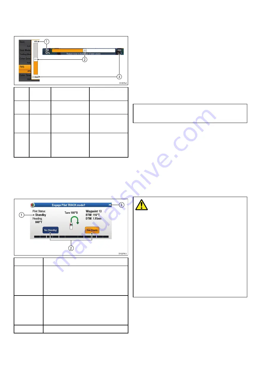
Using control dialogs
Control dialogs enable you to control externally
connected equipment, such as an autopilot unit.
The following diagram shows the main features of
a typical control dialog:
D12279-2
1
3
2
Screen item
Description
1
Status
— provides status information for the
connected equipment. For example, the Pilot
Control dialog displays the locked heading
and current navigation mode for a connected
autopilot unit.
2
Control icons
— provide direct control of
the connected equipment. For example, the
Pilot Control dialog
Standby
and
Track
icons
enable you to instruct a connected autopilot
unit to perform specific functions.
3
Close
— Closes the control dialog.
3.17 Initial set up procedures
Once your display has been installed and
commissioned, Raymarine recommends that you
complete the Startup wizard and perform some
additional procedures.
Startup wizard
When you power-up the display for the first time or
after a system reset a Startup Wizard is displayed.
The wizard guides you through the following basic
configuration settings:
1.
Language
2.
Boat type
3.
Configure Units (Units of measure)
4.
Boat Details
Note:
These settings can also be set at any time
using the menus accessible from
Homescreen
> Customize
.
Additional settings
In addition to the settings covered by the Wizard,
it is also recommended that the following initial set
up tasks are completed:
• Set your date and time preferences.
• Designate the data master.
• Select the GPS data source.
• Familiarize yourself with the product using
Simulator Mode.
Warning: Minimum Safe Depth,
Beam and Height
Depending on cartography vendor, the
minimum safe settings are used during
automatic route generation, they are used
to restrict created routes from entering
water that is not suitable for the vessel.
Data is taken from compatible cartography.
Minimum safe settings are user defined
calculations. As both of these factors
are outside of Raymarine’s control;
Raymarine will not be held liable for
any damage, physical or otherwise,
resulting from the use of the automatic
route generation feature or the
Minimum
Safe Depth
,
Minimum Safe Beam
or
Minimum Safe Height
settings.
Minimum safe vessel depth
As part of the
Initial startup wizard
the
Minimum
Safe Depth
value can be set.
Minimum Safe Depth
can be established by adding
together:
• Maximum Vessel Draft (i.e. the distance from the
waterline to the lowest point of a vessel’s keel.)
• Safety Margin (an adequate clearance below the
keel to allow for draft variation and changes in
water or bottom conditions.)
42
LightHouse multifunction display operation instructions
Summary of Contents for A65
Page 2: ......
Page 8: ...8 LightHouse multifunction display operation instructions...
Page 12: ...12 LightHouse multifunction display operation instructions...
Page 24: ...24 LightHouse multifunction display operation instructions...
Page 62: ...62 LightHouse multifunction display operation instructions...
Page 90: ...90 LightHouse multifunction display operation instructions...
Page 118: ...118 LightHouse multifunction display operation instructions...
Page 122: ...122 LightHouse multifunction display operation instructions...
Page 140: ...140 LightHouse multifunction display operation instructions...
Page 198: ...198 LightHouse multifunction display operation instructions...
Page 232: ...232 LightHouse multifunction display operation instructions...
Page 308: ...308 LightHouse multifunction display operation instructions...
Page 316: ...316 LightHouse multifunction display operation instructions...
Page 338: ...338 LightHouse multifunction display operation instructions...
Page 346: ...346 LightHouse multifunction display operation instructions...
Page 370: ...370 LightHouse multifunction display operation instructions...
Page 374: ...374 LightHouse multifunction display operation instructions...
Page 389: ......
Page 390: ...www raymarine com...


