11
CANbus Device Set Up:
111
CANBUS DEVICE SET UP
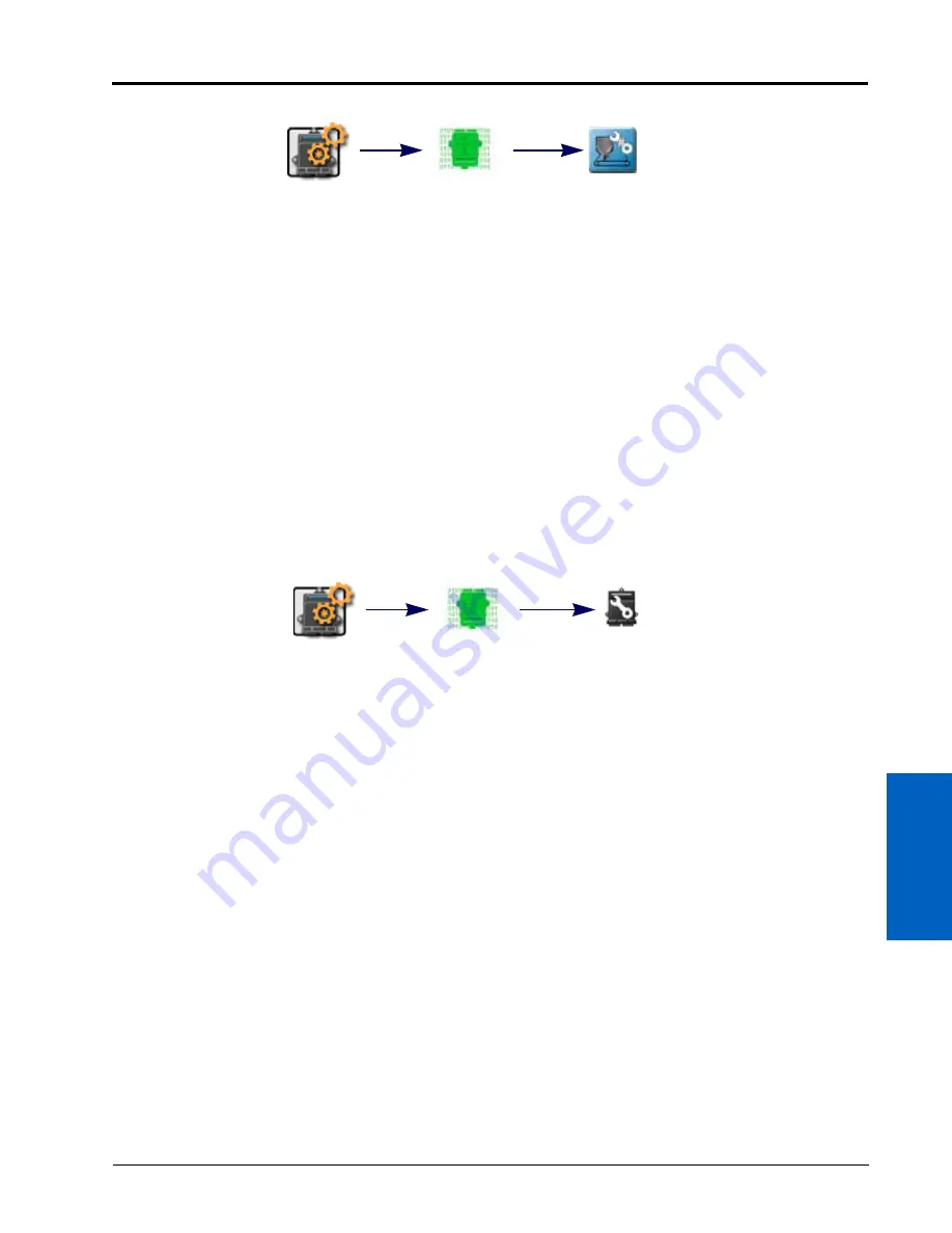
To configure a multi-channel node:
1. Touch the Edit icon in the Machine Panel to view the machine devices.
2. Locate and select the CAN System module. The CAN System tab will be displayed.
3. Touch the Reset Product Control Node button at the bottom of the CAN system tab. A prompt with the
currently set number of channels will be displayed.
4. Touch the Current Channel value and use the on-screen keypad to enter the desired number of channels to be
controlled via the multi-channel node.
NOTE:
ROS will only allow the operator to enter a value for the maximum number of channels currently
available via the multi-channel node. Contact a local Raven dealer for more information or to
purchase additional node capabilities.
5. Touch the OK button to accept the displayed value. The ROS device will reconfigure the multi-channel node
and restart CANbus communications.
READDRESSING CONTROL CHANNELS
If the ROS device is unable to detect a CANbus node on startup, troubleshoot the CANbus and the node (see the
CANbus Troubleshooting section on page 118) and then readdress the CANbus:
NOTE:
Only nodes offering product control channels will need to be addressed (single or multi-product
nodes, motor control, planter or seeder control nodes, etc.). When readdressing multi-channel
control nodes, configure the number of channels on the node prior to readdressing the CANbus.
Review Multi-Channel Node or ECU Configuration section on page 110 for details on configuring
multi-channel control nodes.
RAVEN CANBUS NETWORK
1. Touch the Edit icon in the Machine Panel to view the machine devices.
2. Locate and select the CAN System module. The CAN system tab will display.
3. Touch the Readdress CAN button at the bottom of the CAN System tab.
4. Confirm the readdressing operation for nodes offering product control channels.
5. Cycle logic power to the node to be assigned to control channel 1. To cycle power:
•
remove the logic power fuse on the cable connected directly to the node,
•
disconnect the node harness from the CANbus network (generation 2 systems), or
•
remove the node connector with the power and ground (red and white lead wires).
6. Repeat step 5 and cycle logic power for any remaining nodes connected to the CANbus to assign remaining
control channels as necessary.
7. When all product control nodes on the CANbus system have been assigned to control channels, touch the
“OK” button to finish the readdressing process.
Edit
CAN System
Configure Multi-
Channel Node
Edit
CAN System
Readdress
CAN
Summary of Contents for viper
Page 16: ...CHAPTER 2 8 Viper Viper 4 Installation Operation Manual ...
Page 48: ...CHAPTER 6 40 Viper Viper 4 Installation Operation Manual ...
Page 67: ...File Manager 59 FILE MANAGER ...
Page 68: ...CHAPTER 7 60 Viper Viper 4 Installation Operation Manual ...
Page 112: ...CHAPTER 9 104 Viper Viper 4 Installation Operation Manual ...
Page 174: ...CHAPTER 16 166 Viper Viper 4 Installation Operation Manual ...
Page 176: ...CHAPTER 17 168 Viper Viper 4 Installation Operation Manual ...


