C
HAPTER
11
116
Viper/Viper 4+ Installation & Operation Manual
PHYSICAL SWITCH BOX SETUP
This section only applies when using a Raven Product Control Node with Boom Sense Unlock with a Master Switch.
The Raven Product Controller node with Boom Sense unlock has the ability to be configured with only a single
master switch. This requires a =12V signal for all sections to apply. When this configuration is used, it is necessary
to assign all sections to switch 1 on the physical switch box.
ON-SCREEN SWITCH BOX OPTIONS
The on-screen switch box option provides an option to control implement status right on the ROS display. This
option may be preferable for equipment without existing switches or when a physical switch box is impractical or
undesirable for operations.
MASTER SWITCH OPTIONS
To configure ROS master switch options:
NOTE:
The master switch module will not be available if a boom speed node or other switch hardware (e.g.
Raven Switch Box or SwitchPro) is detected on the CANbus.
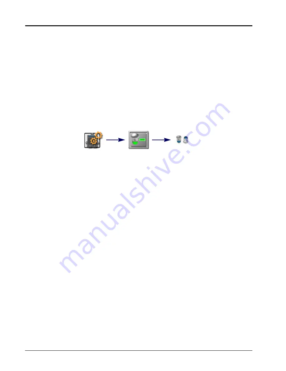
1. Touch the Edit icon in the Machine Panel to view the machine devices.
2. Locate and select the Master Switch module.
3. Select the option necessary and best suited for implement control:
On-Screen Master Switch.
Select this option to allow the operator to use an on-screen master switch widget to
toggle the implement status.
With this option selected, the operator will need to add the master switch widget to the guidance display in
order to toggle coverage history on or off during field operations.
NOTE:
The on-screen master switch is only capable of toggling coverage for a single section or full
implement. Review the Widget Selection and Set Up section on page 138 for assistance with setting
up and adding widgets to the guidance display for field operations. Refer to the On-Screen Switch
Box Options section on page 116 for information on using an on-screen switch box to control
individual sections on an implement.
Remote Master Switch.
Select this option if a remote master or proximity switch is connected to the “Remote
Switch” connector on the chassis cable. Review the Raven CANbus System Installation Manual for additional
information on installing the generation 1 interface or generation 2 chassis cable platforms.
ON-SCREEN SECTION SWITCHES
NOTE:
Additional hardware may be required to control individual sections using the on-screen switch box.
Contact a local Raven dealer for additional assistance or ordering information.
The on-screen switch box option will not be available if a Raven Switch Pro or CAN Switch Box is
detected on the CANbus.
Edit
Master Switch
Master
Switch
Summary of Contents for viper
Page 16: ...CHAPTER 2 8 Viper Viper 4 Installation Operation Manual ...
Page 48: ...CHAPTER 6 40 Viper Viper 4 Installation Operation Manual ...
Page 67: ...File Manager 59 FILE MANAGER ...
Page 68: ...CHAPTER 7 60 Viper Viper 4 Installation Operation Manual ...
Page 112: ...CHAPTER 9 104 Viper Viper 4 Installation Operation Manual ...
Page 174: ...CHAPTER 16 166 Viper Viper 4 Installation Operation Manual ...
Page 176: ...CHAPTER 17 168 Viper Viper 4 Installation Operation Manual ...


