background image

4

9850060 R02 - 2020-2021 850 AXYS™ Long Track Snowmobile Service Manual
© Copyright Polaris Inc.

4.9

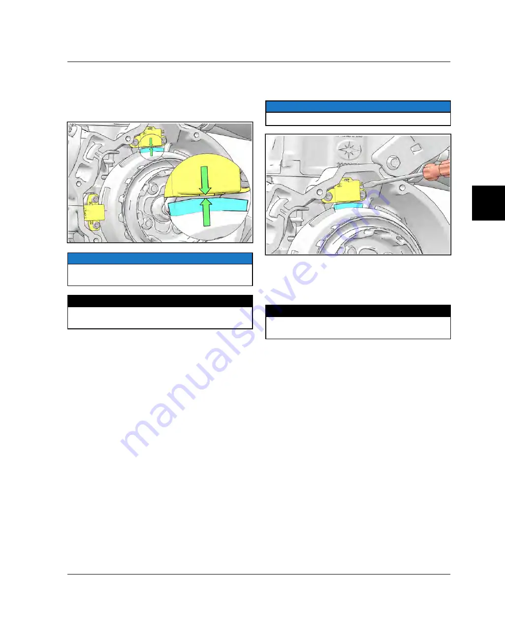
CRANKSHAFT POSITION SENSOR AIR
GAPS

Hard engine starting, erratic reverse operation, and poor
engine performance can occur if the CPS air gap(s) are
outside specification.

NOTICE

The sensor bases are not slotted. Only minor deflection

adjustments can be made.

MEASUREMENT

Crankshaft Position Sensor Air Gap:

.020 - .030 in (0.5 - 0.8 mm)

AIR GAP INSPECTION/ADJUSTMENT

1. Rotate the crankshaft/flywheel so that an encoder rib

is positioned directly underneath the sensor being
measured.

2. Insert the blade of a .030" feeler gauge between the

rib and sensor face. If there is no drag felt on the
feeler gauge, the CPS must be adjusted.

3. To adjust a CPS, use an 8 inch pry bar to carefully

deflect the sensor.

4. Place the tip of the small pry bar between the back of

the sensor and crankcase. insert a .012" feeler gauge
between the sensor face and encoder rib.

NOTICE

Do not pry on the individual sensor wires.

5. Gently pry the sensor toward the encoder rip until the

gauge begins to bind between the components.

6. Re-measure the air gap. The gap should be between

the specification listed below.

MEASUREMENT

Crankshaft Position Sensor Air Gap:

.020 - .030 in (0.5 - 0.8 mm)

ENGINE ELECTRICAL

Summary of Contents for 850 PRO-RMK 155 2.6" QD 2021

Page 1: ...n authorized dealer for service We value your input and appreciate any assistance you can provide in helping make these publications more useful Please provide any feedback you may have regarding this manual Authorized dealers can submit feedback using Ask Polaris Click on Ask Polaris and then click on Service Manual Service Literature Question Consumers please provide your feedback in writing to ...

Page 2: ...on which if not avoided WILL result in death or serious injury WARNING SAFETY ALERT WARNING indicates a hazardous situation which if not avoided COULD result in death or serious injury CAUTION SAFETY ALERT CAUTION indicates a hazardous situation which if not avoided COULD result in minor to moderate injury NOTICE NOTICE provides key information by clarifying instructions IMPORTANT IMPORTANT provid...

Page 3: ...y Vac Registered Trademark of Neward Enterprises Inc Torx Registered Trademark of Textron Hilliard Trademark of the Hilliard Corporation Warn Trademark of Warn Industries FOX Registered Trademark of FOX RACING SHOX RydeFX Registered Trademark of ArvinMeritor Some Polaris factory publications can be downloaded from www polarisindustries com purchased from www purepolaris com or by contacting the ne...

Page 4: ... feedback form has been created for the technician or consumer to provide Polaris with an overall satisfaction rating for this service manual provide comments on your experience or upload pictures video This feedback form is viewable on a mobile device by scanning the QR code or by clicking HERE if viewing this document electronically ...

Page 5: ...y CHAPTER 1 GENERAL INFORMATION CHAPTER 2 MAINTENANCE CHAPTER 3 ENGINE COOLING EXHAUST CHAPTER 4 ENGINE ELECTRICAL CHAPTER 5 FUEL SYSTEM CHAPTER 6 FINAL DRIVE BRAKE SYSTEMS CHAPTER 7 PVT SYSTEM CHAPTER 8 STEERING SUSPENSIONS CHAPTER 9 CHASSIS CHAPTER 10 BATTERY ELECTRICAL ...

Page 6: ......

Page 7: ...RO RMK 163 3 0 TRACK 1 20 2020 850 PRO RMK 174 3 0 TRACK 1 22 2020 850 SKS 155 1 24 MODEL SPECIFICATIONS MODEL YEAR 2021 1 26 2021 850 PRO RMK 155 1 26 2021 850 PRO RMK 155 QD2 2 75 TRACK 1 28 2021 850 PRO RMK 155 QD2 3 0 TRACK 1 30 2021 850 PRO RMK 155 3 0 TRACK 1 32 2021 850 RMK KHAOS 155 1 34 2021 850 RMK KHAOS 155 QD2 2 75 TRACK 1 36 2021 850 RMK KHAOS 155 QD2 3 0 TRACK 1 38 2021 850 RMK KHAOS...

Page 8: ...ON ERRORS 1 87 DIGITAL WRENCH FEATURE MAP 1 88 DIGITAL WRENCH SYSTEM CONFIGURATIONS 1 89 DIGITAL WRENCH DIAGNOSTIC TROUBLE CODES DTCS DISPLAY 1 90 DIGITAL WRENCH DATA LIST DISPLAY 1 91 DIGITAL WRENCH METERS 1 91 DIGITAL WRENCH DATA TRIGGER FREEZE FRAME 1 92 DIGITAL WRENCH SPECIAL TESTS MENU 1 93 DIGITAL WRENCH VEHICLE HISTORICAL INFORMATION 1 93 DIGITAL WRENCH OUTPUT STATE CONTROL TESTING 1 94 DIG...

Page 9: ...VICE NOTES 1 123 DIGITAL MULTI METER DMM NOTES 1 123 STATIC AND DYNAMIC TESTING 1 123 CONNECTOR PROBING GUIDELINES 1 124 TESTING CONTINUITY RESISTANCE 1 125 TESTING FOR A SHORT TO GROUND 1 125 TESTING FOR A SHORT TO VOLTAGE 1 126 TESTING FOR INTERMITTENT CONDITIONS 1 127 TESTING CURRENT FLOW AMPERAGE 1 127 CURRENT DRAW KEY OFF 1 128 TESTING VOLTAGE DROP 1 128 GENERAL INFORMATION 1 ...

Page 10: ... Digital Wrench calibration VEHICLE IDENTIFICATION NUMBER VIN DESIGNATION 2017 Example SN1CBA8G0G3000000 WORLD MFG ID VEHICLE DESCRIPTORS VEHICLE IDENTIFIERS MAK E LINE TYPE ENGINE SIZE ENGINE MODIFIER CHECK DIGIT MODEL YEAR MFG LOCATION INDIVIDUAL SERIAL NO 1 2 3 4 5 6 7 8 9 10 11 12 13 14 15 16 17 S N 1 C B A 6 G 0 G 3 0 0 0 0 0 0 Model Year H 2017 J 2018 K 2019 L 2020 M 2021 TUNNEL DECAL The Tu...

Page 11: ...nnel and printed on the tunnel VIN label q Certification Label e Emissions Certification w Tunnel VIN Model Number Label Stamp IMPORTANT If installing an aftermarket tunnel wrap do not cover the tunnel certification tunnel VIN or emissions certification labels with the wrap If the tunnel wrap doesn t provide an opening for these labels remove the section of wrap where the labels are located GENERA...

Page 12: ...850 AXYS Long Track Snowmobile Service Manual Copyright Polaris Inc ENGINE SERIAL NUMBER LOCATION The engine serial number is located on the identification label q on the engine case next to the recoil cover GENERAL INFORMATION ...

Page 13: ... 27 4010321 28 4010321 31 4110141 32 4110148 67 4010278 68 4010278 PUBLICATION PART NUMBERS 2020 YEAR MODEL MODEL NO OWNER S MANUAL 2020 850 PRO RMK 155 S20EFK8RS 9929772 INTL S20EFK8RE 850 PRO RMK 155 3 0 Track S20EFM8RS INTL S20EFM8RE 850 RMK Khaos 155 S20EFT8RS INTL S20EFT8RE 850 RMK Khaos 155 3 0 Track S20EFN8RS INTL S20EFN8RE 850 PRO RMK 163 S20EGK8RS 850 PRO RMK 163 3 0 Track S20EGM8RS INTL ...

Page 14: ...MK Khaos 155 3 0 QD S21EFT8RC INTL S21EFT8RL 850 RMK Khaos 155 3 0 CC S21EFN8RC 850 PRO RMK 163 2 6 QD S21EGK8RS 850 PRO RMK 163 3 0 QD S21EGK8RC 850 PRO RMK 163 3 0 CC S21EGM8RC 850 RMK Khaos 163 2 6 QD S21EGT8RS 850 RMK Khaos 163 3 0 QD S21EGT8RC INTL S21EGT8RL 850 PRO RMK 165 2 75 QD S21EGK8RB INTL S21EGK8RH 850 RMK Khaos 165 2 75 QD S21EGT8RB INTL S21EGT8RH 850 PRO RMK 174 3 0 QD S21EHK8RC 850...

Page 15: ...tools listed or depicted are mandatory while other tools may be substituted with a similar tool if available Polaris recommends the use of Polaris Special Tools when servicing any Polaris product Dealers may order special tools through the Polaris official tool supplier Bosch Automotive Service Solutions 1 800 345 2233 or https polaris service solutions com GENERAL INFORMATION 1 ...

Page 16: ... 125 in 124 7 cm Estimated Dry Weight 415 lb 188 kg 439 lb 199 kg Electric Start Fuel Capacity 11 5 Gal 43 5 L Oil Capacity 3 9 Qt 3 7 L Cooling System Capacity 5 3 Qt 5 0 L Brake Fluid DOT 4 DRIVE BELT Part Number 3211216 Width 1 47 in 3 73 cm Side Angle 28 Circumference 46 77 in 118 8 cm Center Distance 11 5 in 29 cm QUICKDRIVE Center Distance 7 76 in 19 71 cm Gearing SEE CLUTCHING SETTINGS Reve...

Page 17: ... 75 in 1 6 1 9 cm Stud Protection Maximum Stud Length N A ELECTRICAL Alternator Output Operating Voltage Watts 13 5 VDC Total 13 5 14 5 VDC 500 Idle Ignition Timing Variable Based on RPM Pressure and Temp 2 20 Spark Plug NGK BPR9ES Spark Plug Gap 027 in 70 mm FRONT SUSPENSION Front Suspension Type AXYS RMK React Front Shock Walker Evans Impact Extruded Monotube or Walker Evans Comp Adj Piggyback F...

Page 18: ...b 194kg 452 lb 205 kg Electric Start Fuel Capacity 11 5 Gal 43 5 L Oil Capacity 3 9 Qt 3 7 L Cooling System Capacity 5 3 Qt 5 0 L Brake Fluid DOT 4 DRIVE BELT Part Number 3211216 Width 1 47 in 3 73 cm Side Angle 28 Circumference 46 77 in 118 8 cm Center Distance 11 5 in 29 cm CHAINCASE Center Distance 7 76 in 19 71 cm Gearing SEE CLUTCHING SETTINGS Gear Lube Polaris Synthetic 30W Capacity 8 10 oz ...

Page 19: ... 6 1 9 cm Stud Protection Maximum Stud Length N A ELECTRICAL Alternator Output Operating Voltage Watts 13 5 VDC Total 13 5 14 5 VDC 500 Idle Ignition Timing Variable Based on RPM Pressure and Temp 2 20 Spark Plug NGK BPR9ES Spark Plug Gap 027 in 70 mm FRONT SUSPENSION Front Suspension Type AXYS RMK React Front Shock Walker Evans Impact Extruded Monotube or Walker Evans Comp Adj Piggyback Front Tra...

Page 20: ...timated Dry Weight 420 lb 188 kg 442 lb 200 5 kg Electric Start Fuel Capacity 11 5 Gal 43 5 L Oil Capacity 3 9 Qt 3 7 L Cooling System Capacity 5 3 Qt 5 0 L Brake Fluid DOT 4 DRIVE BELT Part Number 3211216 Width 1 47 in 3 73 cm Side Angle 28 Circumference 46 77 in 118 8 cm Center Distance 11 5 in 29 cm QUICKDRIVE Center Distance 7 76 in 19 71 cm Gearing SEE CLUTCHING SETTINGS Reverse System Electr...

Page 21: ...in 6 60 cm Series 6 Track Tension 0 625 0 75 in 1 6 1 9 cm Stud Protection Maximum Stud Length N A ELECTRICAL Alternator Output Operating Voltage Watts 13 5 VDC Total 13 5 14 5 VDC 500 Idle Ignition Timing Variable Based on RPM Pressure and Temp 2 20 Spark Plug NGK BPR9ES Spark Plug Gap 027 in 70 mm FRONT SUSPENSION Front Suspension Type AXYS RMK React Front Shock Walker Evans Hi Lo Comp Adj Veloc...

Page 22: ...b 188 kg 457 lb 207 3 kg Electric Start Fuel Capacity 11 5 Gal 43 5 L Oil Capacity 3 9 Qt 3 7 L Cooling System Capacity 5 3 Qt 5 0 L Brake Fluid DOT 4 DRIVE BELT Part Number 3211216 Width 1 47 in 3 73 cm Side Angle 28 Circumference 46 77 in 118 8 cm Center Distance 11 5 in 29 cm CHAINCASE Center Distance 7 76 in 19 71 cm Gearing SEE CLUTCHING SETTINGS Gear Lube Polaris Synthetic 30W Capacity 8 10 ...

Page 23: ...cm Series 7 Track Tension 0 625 0 75 in 1 6 1 9 cm Stud Protection Maximum Stud Length N A ELECTRICAL Alternator Output Operating Voltage Watts 13 5 VDC Total 13 5 14 5 VDC 500 Idle Ignition Timing Variable Based on RPM Pressure and Temp 2 20 Spark Plug NGK BPR9ES Spark Plug Gap 027 in 70 mm FRONT SUSPENSION Front Suspension Type AXYS RMK React Front Shock Walker Evans Hi Lo Comp Adj Velocity Fron...

Page 24: ...ed Dry Weight 420 lb 191 kg 444 lb 201 kg Electric Start Fuel Capacity 11 5 Gal 43 5 L Oil Capacity 3 9 Qt 3 7 L Cooling System Capacity 5 5 Qt 5 5 L Brake Fluid DOT 4 DRIVE BELT Part Number 3211216 Width 1 47 in 3 73 cm Side Angle 28 Circumference 46 77 in 118 8 cm Center Distance 11 5 in 29 cm QUICKDRIVE Center Distance 7 76 in 19 71 cm Gearing SEE CLUTCHING SETTINGS Reverse System Electronic Re...

Page 25: ...75 in 1 6 1 9 cm Stud Protection Maximum Stud Length N A ELECTRICAL Alternator Output Operating Voltage Watts 13 5 VDC Total 13 5 14 5 VDC 500 Idle Ignition Timing Variable Based on RPM Pressure and Temp 2 20 Spark Plug NGK BPR9ES Spark Plug Gap 027 in 70 mm FRONT SUSPENSION Front Suspension Type AXYS RMK React Front Shock Walker Evans Impact Extruded Monotube or Walker Evans Comp Adj Piggyback Fr...

Page 26: ...b 196 kg 457 lb 207 kg Electric Start Fuel Capacity 11 5 Gal 43 5 L Oil Capacity 3 9 Qt 3 7 L Cooling System Capacity 5 5 Qt 5 5 L Brake Fluid DOT 4 DRIVE BELT Part Number 3211216 Width 1 47 in 3 73 cm Side Angle 28 Circumference 46 77 in 118 8 cm Center Distance 11 5 in 29 cm CHAINCASE Center Distance 7 76 in 19 71 cm Gearing SEE CLUTCHING SETTINGS Gear Lube Polaris Synthetic 30W Capacity 8 10 oz...

Page 27: ...6 1 9 cm Stud Protection Maximum Stud Length N A ELECTRICAL Alternator Output Operating Voltage Watts 13 5 VDC Total 13 5 14 5 VDC 500 Idle Ignition Timing Variable Based on RPM Pressure and Temp 2 20 Spark Plug NGK BPR9ES Spark Plug Gap 027 in 70 mm FRONT SUSPENSION Front Suspension Type AXYS RMK React Front Shock Walker Evans Impact Extruded Monotube or Walker Evans Comp Adj Piggyback Front Trav...

Page 28: ...04 kg 473 lb 214 kg Electric Start Fuel Capacity 11 5 Gal 43 5 L Oil Capacity 3 9 Qt 3 7 L Cooling System Capacity 5 7 Qt 5 4 L Brake Fluid DOT 4 DRIVE BELT Part Number 3211216 Width 1 47 in 3 73 cm Side Angle 28 Circumference 46 77 in 118 8 cm Center Distance 11 5 in 29 cm CHAINCASE Center Distance 7 76 in 19 71 cm Gearing SEE CLUTCHING SETTINGS Gear Lube Polaris Synthetic 30W Capacity 8 10 oz 23...

Page 29: ... 6 1 9 cm Stud Protection Maximum Stud Length N A ELECTRICAL Alternator Output Operating Voltage Watts 13 5 VDC Total 13 5 14 5 VDC 500 Idle Ignition Timing Variable Based on RPM Pressure and Temp 2 20 Spark Plug NGK BPR9ES Spark Plug Gap 027 in 70 mm FRONT SUSPENSION Front Suspension Type AXYS RMK React Front Shock Walker Evans Impact Extruded Monotube or Walker Evans Comp Adj Piggyback Front Tra...

Page 30: ...g 476 lb 216 kg Electric Start Fuel Capacity 11 5 Gal 43 5 L Oil Capacity 3 9 Qt 3 7 L Cooling System Capacity 5 3 Qt 5 0 L Brake Fluid DOT 4 DRIVE BELT Part Number 3211216 Width 1 47 in 3 73 cm Side Angle 28 Circumference 46 77 in 118 8 cm Center Distance 11 5 in 29 cm CHAINCASE Center Distance 7 76 in 19 71 cm Gearing SEE CLUTCHING SETTINGS Gear Lube Polaris Synthetic 30W Capacity 8 10 oz 237 29...

Page 31: ... 40 in 6 10 cm Series 5 1 2 60 in 6 60 cm Series 6 Track Tension 0 625 0 75 in 1 6 1 9 cm Stud Protection Maximum Stud Length N A ELECTRICAL Alternator Output Operating Voltage Watts 13 5 VDC Total 13 5 14 5 VDC 500 Idle Ignition Timing Variable Based on RPM Pressure and Temp 2 20 Spark Plug NGK BPR9ES Spark Plug Gap 027 in 70 mm FRONT SUSPENSION Front Suspension Type AXYS RMK Adjustable Front Sho...

Page 32: ...in 124 7 cm Estimated Dry Weight 415 lb 188 kg 439 lb 199 kg Electric Start Fuel Capacity 11 5 Gal 43 5 L Oil Capacity 3 9 Qt 3 7 L Cooling System Capacity 5 3 Qt 5 0 L Brake Fluid DOT 4 DRIVE BELT Part Number 3211216 Width 1 47 in 3 73 cm Side Angle 28 Circumference 46 77 in 118 8 cm Center Distance 11 5 in 29 cm QUICKDRIVE Center Distance 7 76 in 19 71 cm Gearing SEE CLUTCHING SETTINGS Reverse S...

Page 33: ... 75 in 1 6 1 9 cm Stud Protection Maximum Stud Length N A ELECTRICAL Alternator Output Operating Voltage Watts 13 5 VDC Total 13 5 14 5 VDC 500 Idle Ignition Timing Variable Based on RPM Pressure and Temp 2 20 Spark Plug NGK BPR9ES Spark Plug Gap 027 in 70 mm FRONT SUSPENSION Front Suspension Type AXYS RMK React Front Shock Walker Evans Impact Extruded Monotube or Walker Evans Comp Adj Piggyback F...

Page 34: ... 7 cm Estimated Dry Weight 415 lb 188 kg 439 lb 199 kg Electric Start Fuel Capacity 11 5 Gal 43 5 L Oil Capacity 3 9 Qt 3 7 L Cooling System Capacity 5 3 Qt 5 0 L Brake Fluid DOT 4 DRIVE BELT Part Number 3211216 Width 1 47 in 3 73 cm Side Angle 28 Circumference 46 77 in 118 8 cm Center Distance 11 5 in 29 cm QUICKDRIVE Center Distance 7 76 in 19 71 cm Gearing SEE CLUTCHING SETTINGS Reverse System ...

Page 35: ...25 in 1 3 1 6 cm Stud Protection Maximum Stud Length N A ELECTRICAL Alternator Output Operating Voltage Watts 13 5 VDC Total 13 5 14 5 VDC 500 Idle Ignition Timing Variable Based on RPM Pressure and Temp 2 20 Spark Plug NGK BPR9ES Spark Plug Gap 027 in 70 mm FRONT SUSPENSION Front Suspension Type AXYS RMK React Front Shock Walker Evans Impact Extruded Monotube or Walker Evans Comp Adj Piggyback Fr...

Page 36: ...7 cm Estimated Dry Weight 415 lb 188 kg 439 lb 199 kg Electric Start Fuel Capacity 11 5 Gal 43 5 L Oil Capacity 3 9 Qt 3 7 L Cooling System Capacity 5 3 Qt 5 0 L Brake Fluid DOT 4 DRIVE BELT Part Number 3211216 Width 1 47 in 3 73 cm Side Angle 28 Circumference 46 77 in 118 8 cm Center Distance 11 5 in 29 cm QUICKDRIVE Center Distance 7 76 in 19 71 cm Gearing SEE CLUTCHING SETTINGS Reverse System E...

Page 37: ... 1 6 1 9 cm Stud Protection Maximum Stud Length N A ELECTRICAL Alternator Output Operating Voltage Watts 13 5 VDC Total 13 5 14 5 VDC 500 Idle Ignition Timing Variable Based on RPM Pressure and Temp 2 20 Spark Plug NGK BPR9ES Spark Plug Gap 027 in 70 mm FRONT SUSPENSION Front Suspension Type AXYS RMK React Front Shock Walker Evans Impact Extruded Monotube or Walker Evans Comp Adj Piggyback Front T...

Page 38: ...kg 452 lb 205 kg Electric Start Fuel Capacity 11 5 Gal 43 5 L Oil Capacity 3 9 Qt 3 7 L Cooling System Capacity 5 3 Qt 5 0 L Brake Fluid DOT 4 DRIVE BELT Part Number 3211216 Width 1 47 in 3 73 cm Side Angle 28 Circumference 46 77 in 118 8 cm Center Distance 11 5 in 29 cm CHAINCASE Center Distance 7 76 in 19 71 cm Gearing SEE CLUTCHING SETTINGS Gear Lube Polaris Synthetic 30W Capacity 8 10 oz 237 2...

Page 39: ... 1 6 1 9 cm Stud Protection Maximum Stud Length N A ELECTRICAL Alternator Output Operating Voltage Watts 13 5 VDC Total 13 5 14 5 VDC 500 Idle Ignition Timing Variable Based on RPM Pressure and Temp 2 20 Spark Plug NGK BPR9ES Spark Plug Gap 027 in 70 mm FRONT SUSPENSION Front Suspension Type AXYS RMK React Front Shock Walker Evans Impact Extruded Monotube or Walker Evans Comp Adj Piggyback Front T...

Page 40: ...ed Dry Weight 420 lb 188 kg 442 lb 200 5 kg Electric Start Fuel Capacity 11 5 Gal 43 5 L Oil Capacity 3 9 Qt 3 7 L Cooling System Capacity 5 3 Qt 5 0 L Brake Fluid DOT 4 DRIVE BELT Part Number 3211216 Width 1 47 in 3 73 cm Side Angle 28 Circumference 46 77 in 118 8 cm Center Distance 11 5 in 29 cm QUICKDRIVE Center Distance 7 76 in 19 71 cm Gearing SEE CLUTCHING SETTINGS Reverse System Electronic ...

Page 41: ...in 6 60 cm Series 6 Track Tension 0 625 0 75 in 1 6 1 9 cm Stud Protection Maximum Stud Length N A ELECTRICAL Alternator Output Operating Voltage Watts 13 5 VDC Total 13 5 14 5 VDC 500 Idle Ignition Timing Variable Based on RPM Pressure and Temp 2 20 Spark Plug NGK BPR9ES Spark Plug Gap 027 in 70 mm FRONT SUSPENSION Front Suspension Type AXYS RMK React Front Shock Walker Evans Hi Lo Comp Adj Veloc...

Page 42: ... 7 cm Estimated Dry Weight 420 lb 188 kg 442 lb 200 5 kg Electric Start Fuel Capacity 11 5 Gal 43 5 L Oil Capacity 3 9 Qt 3 7 L Cooling System Capacity 5 3 Qt 5 0 L Brake Fluid DOT 4 DRIVE BELT Part Number 3211216 Width 1 47 in 3 73 cm Side Angle 28 Circumference 46 77 in 118 8 cm Center Distance 11 5 in 29 cm QUICKDRIVE Center Distance 7 76 in 19 71 cm Gearing SEE CLUTCHING SETTINGS Reverse Syste...

Page 43: ...n 6 99 cm Series 8 Track Tension 0 50 0 625 in 1 3 1 6 cm Stud Protection Maximum Stud Length N A ELECTRICAL Alternator Output Operating Voltage Watts 13 5 VDC Total 13 5 14 5 VDC 500 Idle Ignition Timing Variable Based on RPM Pressure and Temp 2 20 Spark Plug NGK BPR9ES Spark Plug Gap 027 in 70 mm FRONT SUSPENSION Front Suspension Type AXYS RMK React Front Shock Walker Evans Hi Lo Comp Adj Veloci...

Page 44: ...7 cm Estimated Dry Weight 420 lb 188 kg 442 lb 200 5 kg Electric Start Fuel Capacity 11 5 Gal 43 5 L Oil Capacity 3 9 Qt 3 7 L Cooling System Capacity 5 3 Qt 5 0 L Brake Fluid DOT 4 DRIVE BELT Part Number 3211216 Width 1 47 in 3 73 cm Side Angle 28 Circumference 46 77 in 118 8 cm Center Distance 11 5 in 29 cm QUICKDRIVE Center Distance 7 76 in 19 71 cm Gearing SEE CLUTCHING SETTINGS Reverse System...

Page 45: ...2 cm Series 7 Track Tension 0 625 0 75 in 1 6 1 9 cm Stud Protection Maximum Stud Length N A ELECTRICAL Alternator Output Operating Voltage Watts 13 5 VDC Total 13 5 14 5 VDC 500 Idle Ignition Timing Variable Based on RPM Pressure and Temp 2 20 Spark Plug NGK BPR9ES Spark Plug Gap 027 in 70 mm FRONT SUSPENSION Front Suspension Type AXYS RMK React Front Shock Walker Evans Hi Lo Comp Adj Velocity Fr...

Page 46: ... kg 457 lb 207 3 kg Electric Start Fuel Capacity 11 5 Gal 43 5 L Oil Capacity 3 9 Qt 3 7 L Cooling System Capacity 5 3 Qt 5 0 L Brake Fluid DOT 4 DRIVE BELT Part Number 3211216 Width 1 47 in 3 73 cm Side Angle 28 Circumference 46 77 in 118 8 cm Center Distance 11 5 in 29 cm CHAINCASE Center Distance 7 76 in 19 71 cm Gearing SEE CLUTCHING SETTINGS Gear Lube Polaris Synthetic 30W Capacity 8 10 oz 23...

Page 47: ...2 cm Series 7 Track Tension 0 625 0 75 in 1 6 1 9 cm Stud Protection Maximum Stud Length N A ELECTRICAL Alternator Output Operating Voltage Watts 13 5 VDC Total 13 5 14 5 VDC 500 Idle Ignition Timing Variable Based on RPM Pressure and Temp 2 20 Spark Plug NGK BPR9ES Spark Plug Gap 027 in 70 mm FRONT SUSPENSION Front Suspension Type AXYS RMK React Front Shock Walker Evans Hi Lo Comp Adj Velocity Fr...

Page 48: ...ed Dry Weight 420 lb 191 kg 444 lb 201 kg Electric Start Fuel Capacity 11 5 Gal 43 5 L Oil Capacity 3 9 Qt 3 7 L Cooling System Capacity 5 5 Qt 5 5 L Brake Fluid DOT 4 DRIVE BELT Part Number 3211216 Width 1 47 in 3 73 cm Side Angle 28 Circumference 46 77 in 118 8 cm Center Distance 11 5 in 29 cm QUICKDRIVE Center Distance 7 76 in 19 71 cm Gearing SEE CLUTCHING SETTINGS Reverse System Electronic Re...

Page 49: ...75 in 1 6 1 9 cm Stud Protection Maximum Stud Length N A ELECTRICAL Alternator Output Operating Voltage Watts 13 5 VDC Total 13 5 14 5 VDC 500 Idle Ignition Timing Variable Based on RPM Pressure and Temp 2 20 Spark Plug NGK BPR9ES Spark Plug Gap 027 in 70 mm FRONT SUSPENSION Front Suspension Type AXYS RMK React Front Shock Walker Evans Impact Extruded Monotube or Walker Evans Comp Adj Piggyback Fr...

Page 50: ...Estimated Dry Weight 420 lb 191 kg 444 lb 201 kg Electric Start Fuel Capacity 11 5 Gal 43 5 L Oil Capacity 3 9 Qt 3 7 L Cooling System Capacity 5 5 Qt 5 5 L Brake Fluid DOT 4 DRIVE BELT Part Number 3211216 Width 1 47 in 3 73 cm Side Angle 28 Circumference 46 77 in 118 8 cm Center Distance 11 5 in 29 cm QUICKDRIVE Center Distance 7 76 in 19 71 cm Gearing SEE CLUTCHING SETTINGS Reverse System Electr...

Page 51: ...1 6 1 9 cm Stud Protection Maximum Stud Length N A ELECTRICAL Alternator Output Operating Voltage Watts 13 5 VDC Total 13 5 14 5 VDC 500 Idle Ignition Timing Variable Based on RPM Pressure and Temp 2 20 Spark Plug NGK BPR9ES Spark Plug Gap 027 in 70 mm FRONT SUSPENSION Front Suspension Type AXYS RMK React Front Shock Walker Evans Impact Extruded Monotube or Walker Evans Comp Adj Piggyback Front Tr...

Page 52: ... kg 457 lb 207 kg Electric Start Fuel Capacity 11 5 Gal 43 5 L Oil Capacity 3 9 Qt 3 7 L Cooling System Capacity 5 5 Qt 5 5 L Brake Fluid DOT 4 DRIVE BELT Part Number 3211216 Width 1 47 in 3 73 cm Side Angle 28 Circumference 46 77 in 118 8 cm Center Distance 11 5 in 29 cm CHAINCASE Center Distance 7 76 in 19 71 cm Gearing SEE CLUTCHING SETTINGS Gear Lube Polaris Synthetic 30W Capacity 8 10 oz 237 ...

Page 53: ...1 6 1 9 cm Stud Protection Maximum Stud Length N A ELECTRICAL Alternator Output Operating Voltage Watts 13 5 VDC Total 13 5 14 5 VDC 500 Idle Ignition Timing Variable Based on RPM Pressure and Temp 2 20 Spark Plug NGK BPR9ES Spark Plug Gap 027 in 70 mm FRONT SUSPENSION Front Suspension Type AXYS RMK React Front Shock Walker Evans Impact Extruded Monotube or Walker Evans Comp Adj Piggyback Front Tr...

Page 54: ...ed Dry Weight 420 lb 188 kg 442 lb 200 5 kg Electric Start Fuel Capacity 11 5 Gal 43 5 L Oil Capacity 3 9 Qt 3 7 L Cooling System Capacity 5 3 Qt 5 0 L Brake Fluid DOT 4 DRIVE BELT Part Number 3211216 Width 1 47 in 3 73 cm Side Angle 28 Circumference 46 77 in 118 8 cm Center Distance 11 5 in 29 cm QUICKDRIVE Center Distance 7 76 in 19 71 cm Gearing SEE CLUTCHING SETTINGS Reverse System Electronic ...

Page 55: ...in 6 60 cm Series 6 Track Tension 0 625 0 75 in 1 6 1 9 cm Stud Protection Maximum Stud Length N A ELECTRICAL Alternator Output Operating Voltage Watts 13 5 VDC Total 13 5 14 5 VDC 500 Idle Ignition Timing Variable Based on RPM Pressure and Temp 2 20 Spark Plug NGK BPR9ES Spark Plug Gap 027 in 70 mm FRONT SUSPENSION Front Suspension Type AXYS RMK React Front Shock Walker Evans Hi Lo Comp Adj Veloc...

Page 56: ...7 cm Estimated Dry Weight 433 lb 188 kg 457 lb 207 3 kg Electric Start Fuel Capacity 11 5 Gal 43 5 L Oil Capacity 3 9 Qt 3 7 L Cooling System Capacity 5 3 Qt 5 0 L Brake Fluid DOT 4 DRIVE BELT Part Number 3211216 Width 1 47 in 3 73 cm Side Angle 28 Circumference 46 77 in 118 8 cm Center Distance 11 5 in 29 cm QUICKDRIVE Center Distance 7 76 in 19 71 cm Gearing SEE CLUTCHING SETTINGS Reverse System...

Page 57: ...2 cm Series 7 Track Tension 0 625 0 75 in 1 6 1 9 cm Stud Protection Maximum Stud Length N A ELECTRICAL Alternator Output Operating Voltage Watts 13 5 VDC Total 13 5 14 5 VDC 500 Idle Ignition Timing Variable Based on RPM Pressure and Temp 2 20 Spark Plug NGK BPR9ES Spark Plug Gap 027 in 70 mm FRONT SUSPENSION Front Suspension Type AXYS RMK React Front Shock Walker Evans Hi Lo Comp Adj Velocity Fr...

Page 58: ... 7 cm Estimated Dry Weight 420 lb 191 kg 444 lb 201 kg Electric Start Fuel Capacity 11 5 Gal 43 5 L Oil Capacity 3 9 Qt 3 7 L Cooling System Capacity 5 5 Qt 5 5 L Brake Fluid DOT 4 DRIVE BELT Part Number 3211216 Width 1 47 in 3 73 cm Side Angle 28 Circumference 46 77 in 118 8 cm Center Distance 11 5 in 29 cm QUICKDRIVE Center Distance 7 76 in 19 71 cm Gearing SEE CLUTCHING SETTINGS Reverse System ...

Page 59: ...5 in 1 3 1 6 cm Stud Protection Maximum Stud Length N A ELECTRICAL Alternator Output Operating Voltage Watts 13 5 VDC Total 13 5 14 5 VDC 500 Idle Ignition Timing Variable Based on RPM Pressure and Temp 2 20 Spark Plug NGK BPR9ES Spark Plug Gap 027 in 70 mm FRONT SUSPENSION Front Suspension Type AXYS RMK React Front Shock Walker Evans Impact Extruded Monotube or Walker Evans Comp Adj Piggyback Fro...

Page 60: ... 7 cm Estimated Dry Weight 420 lb 188 kg 442 lb 200 5 kg Electric Start Fuel Capacity 11 5 Gal 43 5 L Oil Capacity 3 9 Qt 3 7 L Cooling System Capacity 5 3 Qt 5 0 L Brake Fluid DOT 4 DRIVE BELT Part Number 3211216 Width 1 47 in 3 73 cm Side Angle 28 Circumference 46 77 in 118 8 cm Center Distance 11 5 in 29 cm QUICKDRIVE Center Distance 7 76 in 19 71 cm Gearing SEE CLUTCHING SETTINGS Reverse Syste...

Page 61: ...n 6 99 cm Series 8 Track Tension 0 50 0 625 in 1 3 1 6 cm Stud Protection Maximum Stud Length N A ELECTRICAL Alternator Output Operating Voltage Watts 13 5 VDC Total 13 5 14 5 VDC 500 Idle Ignition Timing Variable Based on RPM Pressure and Temp 2 20 Spark Plug NGK BPR9ES Spark Plug Gap 027 in 70 mm FRONT SUSPENSION Front Suspension Type AXYS RMK React Front Shock Walker Evans Hi Lo Comp Adj Veloci...

Page 62: ... 204 kg 473 lb 214 kg Electric Start Fuel Capacity 11 5 Gal 43 5 L Oil Capacity 3 9 Qt 3 7 L Cooling System Capacity 5 7 Qt 5 4 L Brake Fluid DOT 4 DRIVE BELT Part Number 3211216 Width 1 47 in 3 73 cm Side Angle 28 Circumference 46 77 in 118 8 cm Center Distance 11 5 in 29 cm CHAINCASE Center Distance 7 76 in 19 71 cm Gearing SEE CLUTCHING SETTINGS Gear Lube Polaris Synthetic 30W Capacity 8 10 oz ...

Page 63: ... 1 6 1 9 cm Stud Protection Maximum Stud Length N A ELECTRICAL Alternator Output Operating Voltage Watts 13 5 VDC Total 13 5 14 5 VDC 500 Idle Ignition Timing Variable Based on RPM Pressure and Temp 2 20 Spark Plug NGK BPR9ES Spark Plug Gap 027 in 70 mm FRONT SUSPENSION Front Suspension Type AXYS RMK React Front Shock Walker Evans Impact Extruded Monotube or Walker Evans Comp Adj Piggyback Front T...

Page 64: ...g 476 lb 216 kg Electric Start Fuel Capacity 11 5 Gal 43 5 L Oil Capacity 3 9 Qt 3 7 L Cooling System Capacity 5 3 Qt 5 0 L Brake Fluid DOT 4 DRIVE BELT Part Number 3211216 Width 1 47 in 3 73 cm Side Angle 28 Circumference 46 77 in 118 8 cm Center Distance 11 5 in 29 cm CHAINCASE Center Distance 7 76 in 19 71 cm Gearing SEE CLUTCHING SETTINGS Gear Lube Polaris Synthetic 30W Capacity 8 10 oz 237 29...

Page 65: ... 40 in 6 10 cm Series 5 1 2 60 in 6 60 cm Series 6 Track Tension 0 625 0 75 in 1 6 1 9 cm Stud Protection Maximum Stud Length N A ELECTRICAL Alternator Output Operating Voltage Watts 13 5 VDC Total 13 5 14 5 VDC 500 Idle Ignition Timing Variable Based on RPM Pressure and Temp 2 20 Spark Plug NGK BPR9ES Spark Plug Gap 027 in 70 mm FRONT SUSPENSION Front Suspension Type AXYS RMK Adjustable Front Sho...

Page 66: ...ix Chaincase Gearing Pitch 0 900 0 3000 10 74 1322429 Black 120 320 7044537 Black 155 222 7043063 STR 42 5142586 19 44 74 Pitch 900 1500 3000 5000 10 72 1322428 1500 2100 5000 7000 10 70 1322414 2100 2700 7000 9000 10 68 1322427 2700 3300 9000 11 000 10 66 1321584 3300 3900 11 000 13 000 10 64 1321585 Shaded cells indicate factory settings Use 2 gram lighter shift weights when operating in tempera...

Page 67: ...vation and INTL Stock Setting North American High Elevation Stock Setting Drive Clutch Bolt Torque 80 ft lbs 108 Nm Re torque after running engine 850 PRO RMK RMK KHAOS 155 163 174 3 0 TRACK CLUTCH SETTINGS CLUTCH SETTINGS ALTITUDE meters feet DRIVE CLUTCH DRIVEN CLUTCH Shift Weight Clutch Spring Clutch Spring Driven Helix Quick Drive Gearing Pitch Chaincase Gearing Pitch 0 900 0 3000 10 72 132242...

Page 68: ...82 20 40 72 Pitch 900 1500 3000 5000 10 70 1322414 1500 2100 5000 7000 10 70 1322414 Black 120 320 7044537 Black 155 222 7043063 STR 42 5143881 2100 2700 7000 9000 10 68 1322427 2700 3300 9000 11 000 10 66 1321584 3300 3900 11 000 13 000 10 64 1321585 Shaded cells indicate factory settings Use 2 gram lighter shift weights when operating in temperatures above 40 F 5 C North American Low Elevation a...

Page 69: ...allation Cylinder Fasteners M10 x 1 50 x 127 40 ft lbs 54 N m Apply VES oil under fastener head and to threads prior to installation ENGINE ITEM TORQUE Crankcase Fasteners M8 x 1 25 x 50 24 ft lbs 32 N m Apply VES oil under fastener head and to threads prior to installation Crankcase Fasteners M8 x 1 25 x 80 24 ft lbs 32 N m Apply VES oil under fastener head and to threads prior to installation St...

Page 70: ...tener 168 in lbs 19 Nm ECU Mounting Fasteners 5 ft lbs 7 Nm Front Seat Mount Fastener 36 in lbs 4 Nm FUEL SYSTEM ITEM TORQUE Fuel Tank Rear Mounting Fastener 10 ft lbs 14 Nm Rear Seat Mount Bracket Nuts 10 ft lbs 14 Nm Fuel Tank Bracket Shoulder Fastener 5 ft lbs 7 Nm Fuel Tank Front Mounting Fastener 10 ft lbs 14 Nm PFA Nut 28 ft lbs 38 Nm Throttle Position Sensor Fasteners 31 in lbs 3 5 Nm FINAL...

Page 71: ...ssembly Fastener 36 ft lbs 50 Nm Control Arm Fastener 40 ft lbs 54 Nm AXYS FRONT SUSPENSION Lower Shock Mounting Fastener 18 ft lbs 25 Nm Control Arm Fastening Nut 40 ft lbs 54 Nm Upper Shock Fastening Nut 36 ft lbs 50 Nm Handlebar Hook Fastener 10 ft lbs 13 5 Nm Handlebar Mount Fastener 7 ft lbs 9 5 Nm Tighten Gap Evenly Steering Post Bushing Fasteners 18 ft lbs 25 Nm Lower Steering Post Bushing ...

Page 72: ...lbs 75 Nm 10 Front Brace Fastener 33 ft lbs 45 Nm Rear Rail Brace Fastener 33 ft lbs 45 Nm 10 Rear Torque Arm Brace Shaft Fastener 55 ft lbs 75 Nm 10 Rear Torque Arm Fastener 6 ft lbs 8 Nm AXYS REAR SUSPENSION Front Boogie Wheel Fastener 50 ft lbs 68 Nm Rear Torque Arm to Rear Pivot Fasteners 17 ft lbs 23 Nm Front Torque Arm Tunnel Mounts 47 ft lbs 64 Nm FTS Rail Brace Fasteners 50 ft lbs 68 Nm Fr...

Page 73: ...Structure Screws 22 ft lbs 30 Nm Rear Lower Over Structure Screws 9 ft lbs 12 Nm Upper Snow Flap Fasteners Hand Tight Front Side Support Screws 26 ft lbs 35 Nm Rear Closeoff Acorn Nut 16 in lbs 1 8 Nm ELECTRICAL ELECTRICAL ITEM TORQUE Battery Bracket Nuts 7 ft lbs 10 Nm Battery Bracket Fastener 22 ft lbs 30 Nm Battery Terminal Hardware 36 in lbs 4 Nm Battery Box Bracket Fasteners 22 in lbs 2 5 Nm ...

Page 74: ...m mile mi x 1 6 km km x 0 6214 mile ounces oz x 28 35 grams g fluid ounces fl oz x 29 57 cubic centimeters cc cubic centimeters cc x 03381 fluid ounces grams g x 0 035 ounces pounds lb x 0 454 kg kilogram kg x 2 2046 lbs cubic inches cu in x 16 387 cc cubic centimeters cc x 0 061 cubic inches US quarts x 0 946 liters L liters L x 1 057 US quarts US gallons x 3 785 liters L liters L x 0 264 US gall...

Page 75: ... 1 2 12 1 27 64 12 28 4 6 mm 1 3 4 5 1 9 16 1 4 20 7 1 3 4 12 1 43 64 1 4 28 3 2 4 1 2 1 25 32 5 16 18 F 2 12 1 59 64 5 16 24 I 2 1 4 4 1 2 2 1 32 3 8 16 O 2 1 2 4 2 1 4 3 8 24 Q 2 3 4 4 2 1 2 7 16 14 U 3 4 2 3 4 7 16 20 25 64 METRIC TAP DRILL SIZES TAP SIZE DRILL SIZE DECIMAL EQUIVA LENT NEAREST FRACTION 3 x 50 39 0 0995 3 32 3 x 60 3 32 0 0937 3 32 4 x 70 30 0 1285 1 8 4 x 75 1 8 0 125 1 8 5 x 8...

Page 76: ... 3906 10 mm 0 3937 13 32 0 4063 27 64 0 4219 11 mm 0 4331 7 16 0 4375 29 64 0 4531 15 32 0 4688 12 mm 0 4724 31 64 0 4844 1 2 0 500 13 mm 0 5118 33 64 0 5156 17 32 0 5313 35 64 0 5469 14 mm 0 5512 9 16 0 5625 37 64 0 5781 15 mm 0 5906 19 32 0 5938 39 64 0 6094 5 8 0 625 16 mm 0 6299 FRACTION DECIMAL MM TO INCHES 41 64 0 6406 21 32 0 6563 17 mm 0 6693 43 64 0 6719 11 16 0 6875 45 64 0 7031 18 mm 0 ...

Page 77: ...tem will result in serious engine damage Perform maintenance as recommended Prolonged exposure to petroleum based products may damage paint Always protect painted surfaces when handling fuel Fuel System Deicers If you use non ethanol fuel sometimes labeled non oxygenated Polaris recommends the regular use of a isopropyl based fuel system deicer Add one to two ounces per gallon 8 16 ml per liter of...

Page 78: ...asteners CAUTION Always follow torque specifications as outlined throughout this manual Incorrect torquing may lead to serious machine damage or as in the case of steering components can result in injury or death for the rider s IMPORTANT If a torquing sequence is indicated for nuts bolts or screws start all fasteners in their holes and hand tighten Following the manual exactly tighten to the spec...

Page 79: ...13 Intake Air Temp Sensor Circuit Voltage High This Trouble Code sets if the Intake Air Temperature Sensor Signal is above 4 9 Volts Can be caused by Damaged Wiring a faulty Intake Air Temperature Sensor or ECU Connections 4 P0112 Intake Air Temp Sensor Circuit Voltage Low This Trouble Code sets if the Intake Air Temperature Sensor Signal is below 0 19 Volts Can be caused by Damaged Wiring a fault...

Page 80: ...ssure Sensor or ECU Connections 4 P0192 Fuel Rail Pressure Sensor Voltage Low This Trouble Code Sets if the Fuel Pressure Sensor Circuit is below 0 1V Can be caused by Damaged Wiring a faulty Fuel Pressure Sensor or ECU Connections 18 P0196 Fuel Rail Pressure Below Power Limit This Trouble Code Sets if the Fuel Pressure drops below 3Bar 43 5PSI for 10 seconds Can be caused by a faulty Pump Flange ...

Page 81: ...st Temp Sensor or ECU Connections 4 P1485 Exhaust Temperature Sensor 2 Voltage Low This Trouble Code Sets if the if the Exhaust Temp Sensor 2 Voltage is Below 0 06V Can be caused by Damaged Wiring a faulty Exhaust Temp Sensor or ECU Connections 10 P1486 Exhaust Temperature Sensor 2 Abnormal Rate of Change This Trouble Code sets if the Exhaust Temperature Sensor Signal changes Too Quickly to be con...

Page 82: ...tected in the PTO Cylinder Port Injector Control Circuit Can be caused by Damaged Wiring a faulty Fuel Injector or ECU Connections 5 P0264 PTO Cylinder Port Injector Open Circuit This Trouble Code sets if an Open Circuit Condition is detected in the PTO Cylinder Port Injector Control Circuit Can be caused by Damaged Wiring a faulty Fuel Injector or ECU Connections Knock Sensor 731 2 P0325 Knock Se...

Page 83: ...Sensor Supply 3 Voltage is below an acceptable limit approx 4 5 Volts Can be caused by Damaged Wiring or Faulty Sensor shorted to ground Oil pump 3589 5 P16BA Oil Pump Driver Circuit Open This Trouble Code Sets if the Oil Pump Driver Circuit is Open Can be caused by Damaged Wiring Connections a Faulty Oil Pump Connections or Faulty ECU Connections 12 P16BC Oil Pump Driver Circuit Fault This Troubl...

Page 84: ...e in the Critical Circuit Can be caused by damaged wiring faulty headlight Fuel Pump or Regulator connections 20 P160E Regulator Chassis Voltage Too Low This Trouble Code Sets if the Regulator has detected Low Voltage in the Chassis Circuit Can be caused by damaged wiring or faulty grip heaters 22 P160F Regulator Chassis Short Circuit This Trouble Code Sets if the Regulator has detected Excessive ...

Page 85: ...e Chasssis Supply Voltage is below 14 00V Can be based by faulty wiring faulty regulator or ECU Connections 22V Injector Voltage 520177 3 P1347 Peak Injector Voltage High This Trouble Code sets if the Peak Injector Supply Voltage is above 24 00V Can be based by faulty wiring faulty regulator or ECU Connections 4 P1348 Peak Injector Voltage Low This Trouble Code sets if the Peak Injector Supply Vol...

Page 86: ...is Trouble Code Set Ground Speed PPM 520242 13 P1279 Ground Speed Pulses Per Mile not Programmed This Trouble Code Sets if the Vehicle Speed Sensor Setting is Not Properly Programmed in the ECU Reset the ECU Offset Values to Resolve this Fault Condition EV Position 520178 16 P2627 EV Actuator Position High in Open Position For all E VES Diagnostic Trouble Codes DTCs see E VES Diagnostic Trouble Co...

Page 87: ...or Feedback Faults 520373 2 P1313 Exhaust Valve Actuator Feedback Set Signal Missing 7 P1316 Exhaust Valve Actuator Feedback Position Fault 8 P1319 Exhaust Valve Actuator Feedback Signal Missing 12 P1317 Exhaust Valve Actuator Feedback Actuator Failure 13 P1318 Exhaust Valve Actuator Feedback Calibration Fault Brake Engaged 520555 31 C2418 Riding With Brakes On Moderately Severe This Trouble Code ...

Page 88: ...ssure using a fully charged 12V battery connected to fuel pump prime connectors 58 60 psi 400 413 kPa Fuel Pump Pick Up Sock Inspect the fuel pump pick up sock Replace the sock if it is contaminated with foreign material Engine Mechanical Spark Plug Type Verify the specified spark plugs are installed and gapped to specification NGK BPR9ES Gap 027 0 70 mm Spark Plug Condition Replace fouled damaged...

Page 89: ...rives aggressively and at sustained high speeds Also during the break in time the full shift RPM may be 200 300 RPM lower than when fully broken in Step 1 Document the Basics Document the specific concern Determine when the concern occurs conditions speed throttle position etc Transfer these notes directly to the Ask Polaris case Ask the rider what type of two stroke engine oil they have been usin...

Page 90: ...lean a drive belt with anything more than a solution of warm soapy water and then allow the belt to air dry If chemicals have been used to clean the clutches verify the clutch bushings are not sticking on the stationary shafts If you find tacky belt residue in or around the bushings disassemble the clutch and clean thoroughly Step 4 Inspect Rear Suspension Track Verify the rail sliders are not wor...

Page 91: ...rform fuel pump prime Replace reset Throttle Position Sensor TPS NOTICE If the snowmobile is equipped with a fully charged battery it can be used to supply power to the test connectors If using a stand alone service battery do not place the battery in the tunnel footwells Place the battery on the floor next to the engine compartment DIGITAL WRENCH SPECIAL TOOLS TOOL PART NUMBER PC Laptop with Micr...

Page 92: ...lable 3 If a newer update is available it should be downloaded before using Digital Wrench DIGITAL WRENCH UPDATING SOFTWARE Updates are released for Digital Wrench via the Internet at http polaris diagsys com The Digital Wrench website can also be accessed through the dealer website at www polarisdealers com NOTICE Only authorized Polaris dealers and distributors can access the dealer website 1 Lo...

Page 93: ...re running the install 8 When the update is complete the version shown on the right side of the Digital Wrench start up screen should match the update you just downloaded NOTICE Versions and updates are subject to change DIGITAL WRENCH COMMUNICATION ERRORS If you experience problems connecting to a vehicle or any Digital Wrench related problem visit the Digital Wrench Knowledge Base for the most c...

Page 94: ...ensor and ECU information in a grid meter or chart format Enter customer and vehicle information and view ECU Identification View information from the main ECU sensors Load the Vehicle Home Page Set up data capture and record functions Open the Software Configuration Screen Perform specialized testing and adjustment functions service reports Run the Help System Open the ASSERT ASK form Prints the ...

Page 95: ...ect preferred language e Select displayed units of measurement US or Metric r Select PC Laptop COM port Use this drop down menu if the SmartLink cable is not recognized by the PC Laptop t Debugging Mode Use when instructed by Polaris Service to determine Digital Wrench vehicle communication issues y Help Balloons Auto Update Turn these features on off based on preference If auto updates is turned ...

Page 96: ...ine running Run the engine on a test stand in a well ventilated area as specified to attempt to set active code DIGITAL WRENCH DTC DISPLAY REF DESCRIPTION q DTC P Code w Controller providing the code ECU or Instrument Cluster e Description of DTC r Status Current or Historic t Number of occurrences y Detailed DTC explanation guided diagnostics if available u Clear DTC list Clicking on the Detailed...

Page 97: ...k or to add or subtract data fields Up to 14 items can be displayed on the screen at one time Click the save button to save the current view as a custom data map Click the folder button to display more preset data lists or create a customized data list NOTICE Some components require the engine to be running or power supplied to the CRITICAL PWR test connector to display data For example the EV act...

Page 98: ... of either data items if data item is selected as the trigger or trouble codes if trouble code is selected as the trigger r Enable or reset trigger recording In the example shown below TPS Volts was selected as the Data Item Trigger Digital Wrench prompts the user to select the Comparison t and the Value In this case the Comparison was set to Greater Than and the Value was set to 3 50 volts After ...

Page 99: ...ns has guided step by step instructions DIGITAL WRENCH VEHICLE HISTORICAL INFORMATION Vehicle Historical Information is located under the Special Tests Menu The screen will show the user total engine run time number or engine overheat and shut down events and total TPS or engine RPM history in hours DIGITAL WRENCH VEHICLE HISTORICAL INFORMATION REF DESCRIPTION q Event Counter This table logs the n...

Page 100: ... initiate the test IMPORTANT Verify there is a sufficient amount of fuel in the fuel tank to prevent fuel pump damage when performing the fuel pump test NOTICE Test items may appear different than what is shown and are vehicle specific Some test items require battery power to be connected to the DC PWR Test connector For example When testing the chassis relay Load Shed battery power must be connec...

Page 101: ...laris dealer number is entered on the Digital Wrench Configurations Screen After creating a Service Report scroll up and down through the report to verify all of the data items are present NOTICE To obtain the most accurate data information run the engine on a test stand in a well ventilated area Remember to supply power to the instrument cluster if you want instrument cluster information on the S...

Page 102: ...o the internet prior to performing the ECU replacement procedure NOTICE Service replacement ECUs are formatted as no start ECUs and will not allow the engine to run or the user to set fuel injector color oil pump flow offset etc until the ECU is set with the correct vehicle engine model number The ECU replacement procedure copies the original ECU s vehicle information to the PC laptop and then tra...

Page 103: ...t the model year product line and vehicle description by selecting the Change Vehicle Type icon 9 Select the Special Tests icon Select ECU Injector Oil Pump Replacement 10 On the following screen select ECU Replacement 11 The next screen will prompt the user to verify the defective ECU is connected to the vehicle and the Chassis Power Up harness is connected Click Done Continue to proceed 12 After...

Page 104: ...LACEMENT PROCEDURE 1 Follow steps 1 through 11 in the ECU replacement procedure 2 Digital Wrench will notify the user that it is unable to communicate with the ECU Click on Done Continue 3 The next screen asks the user to enter the vehicle model number and serial number Enter the correct model and serial numbers for the vehicle into the data fields and then click on Continue IMPORTANT The model an...

Page 105: ...r can be found on the oil pump housing decal or the original ECU s information decal Click on Continue after entering the offset number IMPORTANT Severe engine damage may occur if the wrong oil pump offset number code is entered 7 Digital Wrench will display the model number and serial number the user entered at step 3 Verify these numbers are accurate before clicking Continue 8 Disconnect battery...

Page 106: ...e base of each fuel injector When replacing fuel injectors reference this color band to ensure the right fuel map is selected using Digital Wrench 1 Obtain a fully charged 12 volt battery and the Chassis Power Up Harness Chassis Power Up Harness PS 47296 B 2 Open the left engine compartment panel 3 Connect the Next Gen Service Power Harness to the diagnostic connector on the wiring harness Next Ge...

Page 107: ...k Done Continue to proceed 11 Digital Wrench will scan the ECU and display the current fuel injector color code on the screen If the fuel injectors installed on the engine are a different color than what is shown click on the correct color box on the right side of the screen Click on Continue 12 Digital Wrench will set the fuel injector setting in the ECU After this process is completed disconnect...

Page 108: ... used 1 Verify the most current update has been downloaded and loaded into Digital Wrench 2 Obtain a fully charged 12 volt battery and the Chassis Power Up Harness Chassis Power Up Harness PS 47296 B 3 Open the left engine compartment panel 4 Connect the Next Gen Service Power Harness to the diagnostic connector on the wiring harness Next Gen Service Power Harness PS 52573 5 Connect one of the Cha...

Page 109: ...Oil Pump Replacement 12 The next screen will display the current offset value at the top This number must match the number on the oil pump and the ECU label If the offset number on the oil pump does not match what is shown on the screen enter the correct three digit number into the New Oil Pump Offset field Click Continue to proceed 13 After setting the correct oil pump flow offset number in the E...

Page 110: ...s procedure must be performed when new fuel injectors are installed on the engine 1 Obtain a fully charged 12 volt battery and the Chassis Power Up Harness Chassis Power Up Harness PS 47296 B 2 Open the left engine compartment panel 3 Connect the Next Gen Service Power Harness to the diagnostic connector on the wiring harness Next Gen Service Power Harness PS 52573 4 Connect one of the Chassis Pow...

Page 111: ...to the vehicle and PC laptop 7 Start Digital Wrench and select the appropriate vehicle 8 Select the Special Tools Tool Box menu and then Service Procedures 9 The next screen will prompt the user to select the desired operation Select Break In Timer Reset 10 On the next screen click on Fuel Break In Reset GENERAL INFORMATION 1 ...

Page 112: ...s PS 47296 B 2 Open the left engine compartment panel 3 Connect the Next Gen Service Power Harness to the diagnostic connector on the wiring harness Next Gen Service Power Harness PS 52573 4 Connect one of the Chassis Power Up harness leads to the ECU PWR diagnostic test connector on the Next Gen Service Power Harness 5 Connect the power up harness to the battery NOTICE If the snowmobile is equipp...

Page 113: ...t work if the battery cannot supply the required voltage to the actuator Do not perform this procedure with a partially charged battery Verify the battery provides a minimum of 12 5 volts before attempting procedure Verify all wires are in good condition and connectors are connected to the actuator and ECU IMPORTANT Do not attempt to increase battery voltage by connecting batteries in series EV ac...

Page 114: ...he next screen will prompt the user to select the desired operation Select Exhaust Valve Learn 10 The next screen will instruct the user to perform all instructions and procedures exactly as described Click on Done Continue 11 Digital Wrench will begin the learn procedure by checking for faults If the software determines there is insufficient battery voltage to complete the process it is here when...

Page 115: ...its 13 At the end of the procedure the software will check for any faults that may have occurred 14 If no faults are encountered this screen will appear noting the procedure has successfully completed Press the red X button to return to the main menu 15 If a fault were to occur an error screen will appear describing what the fault was and how to resolve the issue Typically the fault will be caused...

Page 116: ...S 52573 4 Connect one of the harness leads to the ECU PWR test diagnostic connector 5 Connect the power up harness to the battery NOTICE If the snowmobile is equipped with a fully charged battery it can be used to supply power to the test connectors If using a stand alone service battery do not place the battery in the tunnel footwells Place the battery on the floor next to the engine compartment ...

Page 117: ...urplus oil from accumulating in the crankcase The Oil Pump Prime procedure is used to purge the engine oil supply lines of air and to verify the ECU can drive the oil pump NOTICE Fill the oil tank with oil prior to starting this procedure Verify the engine oil supply lines are connected to the engine and the oil pump supply hose is connected to the pump and oil tank The Oil Pump Prime Procedure is...

Page 118: ...power to the test connectors If using a stand alone service battery do not place the battery in the tunnel footwells Place the battery on the floor next to the engine compartment 6 Connect the SmartLink cable to the vehicle and PC laptop 7 Start Digital Wrench and select the appropriate vehicle 8 Select the Special Tools Tool Box menu and then Service Procedures 9 The next screen will prompt the u...

Page 119: ...l applications around the dealership is more likely to cause a reprogramming problem than one dedicated to Digital Wrench diagnostics only OBTAINING THE LATEST UPDATE Reprogramming updates are provided periodically and contain the most recent calibrations CLOSE NON ESSENTIAL PROGRAMS Polaris recommends that you DO NOT install non essential programs on a Service Department laptop Camera detection s...

Page 120: ...ower up harness to the battery NOTICE If the snowmobile is equipped with a fully charged battery it can be used to supply power to the test connectors If using a stand alone service battery do not place the battery in the tunnel footwells Place the battery on the floor next to the engine compartment 7 Connect the SmartLink cable to the vehicle and PC laptop 8 Start Digital Wrench on the laptop 9 S...

Page 121: ...ck on ReFlash Authorization from the Service and Warranty drop down menu 14 Enter or paste the Request Code into the box 15 Select the same file type from the list that you selected previously while in Digital Wrench Enter the VIN along with the customer s name and address When completed click the Authorize button once to proceed 16 An Authorization Key will appear in the upper left corner of the ...

Page 122: ...mber ECU part number VIN calibration software and instrument cluster software are loaded onto the ECU To view the vehicle information follow these steps 1 Obtain a fully charged 12 volt battery and the Chassis Power Up Harness Chassis Power Up Harness PS 47296 B 2 Open the left engine compartment panel 3 Connect the Next Gen Service Power Harness to the diagnostic connector on the wiring harness N...

Page 123: ...obile equipped with the PIDD and a 12V battery the PIDD can be powered by turning the key to the ON position ECU INFORMATION The drop down menu q will display what information is shown Click to select Engine Controller Item w is the model number of the vehicle the ECU is installed on This is the information transferred from the ECU when a service replacement ECU is installed Item e is the vehicle ...

Page 124: ...MATION The drop down menu q will display what information is shown Click to select Instrument Cluster Item w is the serial number for the instrument cluster When the cluster is an PIDD this is the number used when registering the cluster with Ride Command Item e is the software program version number GENERAL INFORMATION ...

Page 125: ...Minimum operating system Android 3 1 Honeycomb or higher Android 4 0 or higher preferred NOTICE The PMDW app will not work on Microsoft Windows 8 or Apple IOS products Dual core processor 2 GB internal memory external micro SD 32 or 64 GB slot 500 MB RAM Rear facing camera with minimum 3 0 mega pixel resolution with auto continuous focus Video microphone and voice to text capable Internet and Blue...

Page 126: ...or extended periods of time should be inspected for glazing at 1 000 mile intervals Replace as required CORD POP OUT Inspect drive driven clutch alignment motor mounts and deflection Set the driven clutch float Remove the belt during off season storage period DRIVE CLUTCH PREMATURE WEAR Verify the correct clutch weight spring package is installed Inspect the spider rollers bushings for damage and ...

Page 127: ...ated on speedometer Lower the gear ratio Remove windage plates from the driven clutch If possible move to better snow conditions and reduce RPM Avoid riding in very high ambient temperatures Ice and snow piled up between the track and tunnel overnight or after stopping for a long period of time enough to re freeze the snow Break loose snow and ice under the tunnel Allow a longer than normal warm u...

Page 128: ...s thin film of oil lubricates the Seal to ensure low friction and reduces the corrosion rate of the Piston Rod Vehicle operating conditions have a high impact on how much shock oil might be present on the seal and shock body i e road conditions and operating temperature It is important to properly identify the difference between normal operation weepage or misting and a shock that has a leak Below...

Page 129: ...a DMM will only work in one scenario and slight variables can provide you with misleading results The testing practices described in this chapter are more certain and rely only on the DMM and your knowledge STATIC AND DYNAMIC TESTING There are many methods for testing a DC circuit These methods fall into one of two categories either static or dynamic STATIC TESTING The two most common forms of sta...

Page 130: ... is held upside down this is an indication that the female connector in the harness has insufficient tension and will cause connection issues You can either replace that harness or service it by replacing the terminal or attempting to adjust tighten the tang in the female terminal For a video demonstration scan the QR code below or right click it and select open in new tab BACK PROBING Back probin...

Page 131: ...eturn to ground B so much more of it can flow than the circuit is designed for This causes the circuit s protection device either a fuse or circuit breaker to open protecting the circuit from damage There are many possible causes of a short to ground here are some The harness rubbing against a component that is grounded such as the frame chassis component or engine A component s internal circuitry...

Page 132: ...he circuit Testing Continuity Resistance page 1 125 4 Ensure you have checked for a short to ground Testing For A Short To Ground page 1 125 5 Ensure that neither end of the circuit is connected 6 Set your DMM to DC volts 7 Connect one meter lead securely to the battery negative post 8 Connect the other lead to either end of the disconnected circuit Ensure you are using the correct adapter Connect...

Page 133: ...ble insulation damage Improper routing especially when it leads to chaffing or heat damage especially near exhaust You may need to use different techniques to duplicate these concerns These include but are not limited to Moving the harness by wiggling it or flexing certain areas Pulling at or near the suspected connector Pushing in different directions to flex the connector body and try to isolate...

Page 134: ...o to sleep after switched power is removed 8 Maximum allowable is 10 milliamps If your meter is ranged to the 10 Amp scale this will appear as 0 010 Amps Current Draw Key Off Maximum of 01 DCA 10 mA 9 If over 10 milliamps go to the fuse block and start systematically removing one fuse at a time until the value drops indicating the circuit that requires attention TESTING VOLTAGE DROP NOTICE If you ...

Page 135: ...60 R02 2020 2021 850 AXYS Long Track Snowmobile Service Manual Copyright Polaris Inc 1 129 For a video demonstration scan the QR code below or right click it and select open in new tab GENERAL INFORMATION 1 ...

Page 136: ...1 130 9850060 R02 2020 2021 850 AXYS Long Track Snowmobile Service Manual Copyright Polaris Inc NOTES GENERAL INFORMATION ...

Page 137: ...GINE ANTIFREEZE 2 17 HOOD SIDE PANEL SERVICE 2 18 AXYS SIDE PANELS 2 18 HOOD REMOVAL INSTALLATION 2 19 ENGINE MAINTENANCE 2 20 THROTTLE LEVER FREEPLAY INSPECTION 2 20 THROTTLE LEVER FREEPLAY ADJUSTMENT 2 20 SPARK PLUG MAINTENANCE 2 21 SPARK PLUG WIRE CAP MAINTENANCE 2 21 COOLING SYSTEM MAINTENANCE 2 22 COOLING SYSTEM OVERVIEW 2 22 COOLANT BOTTLE LEVEL CHECK 2 22 COOLING SYSTEM BLEEDING 2 23 DRIVE ...

Page 138: ... 2 46 REAR SUSPENSION INSPECTION 2 47 RAIL SLIDER INSPECTION 2 49 TRACK INSPECTION 2 49 TRACK ALIGNMENT 2 50 TRACK TENSION INSPECTION 2 50 TRACK TENSION ADJUSTMENT 2 51 TRACK TENSION SPECIFICATIONS 2 52 ELECTRICAL SYSTEM MAINTENANCE 2 53 BATTERY MAINTENANCE 2 53 DRY SHIPPED AGM BATTERY MAINTENANCE 2 53 LEAD ACID LOW MAINTENANCE BATTERY MAINTENANCE 2 53 BATTERY REMOVAL 2 54 BATTERY INSTALLATION 2 5...

Page 139: ...2 9850060 R02 2020 2021 850 AXYS Long Track Snowmobile Service Manual Copyright Polaris Inc 2 3 STORING THE SNOWMOBILE 2 63 MAINTENANCE ...

Page 140: ...rse if equipped must not be engaged during engine tune ups NON IONIZING RADIATION This vehicle emits some electromagnetic energy People with active or non active implantable medical devices such as heart monitoring or controlling devices should review the limitations of their device and the applicable electromagnetic standards and directives that apply to this vehicle NOTICE The speedometer may gi...

Page 141: ...out of the compartment 6 When reinstalling the drive belt into the container fold the belt as shown Verify that the belt loop at the rear of the container is positioned slightly higher than the front loop 7 Slide the container into the engine compartment at an angle 8 Position the container bracket onto the bumper tube and rotate it downward 9 Reinstall the spark plug wrench into the bracket and t...

Page 142: ...ous engine damage Oils may also be incompatible and the result could be sludge formation filter blockage and reduced cold weather flow rates All Polaris oils are compatible with each other Drive with extra caution during the break in period Perform regular checks on fluid levels lines and all other important areas of the snowmobile Always check and fill the oil bottle when refueling IMPORTANT Seri...

Page 143: ...ce checks and adjustments several pre ride pre season and storage inspections operational checks are required PRE RIDE INSPECTION The following items should be inspected pre ride ITEM INSPECTION CHECK Drive Driven Clutch Inspect the drive belt condition runout Engine Check for proper coolant level Brake System Inspect brake lever Inspect parking brake Electrical System Inspect auxiliary shut off s...

Page 144: ...Condition C Drive Belt Tension I Engine Engine Mounts I Recoil Handle Rope Function I Spark Plugs I Exhaust Pipe I Exhaust System Retaining Springs I Coolant Level I Cooling Hoses Pipes I Brake System Brake Lever Hose Condition Routing I Fluid Level Leaks Fluid Condition I Brake Pads Brake Disc I Brake System I Fuel System Throttle Lever Throttle Cable I Fuel Vent Hoses I Oil Hoses I Air Box I L L...

Page 145: ...I Chassis Suspension Ski Fasteners C Hood Side Panel Fasteners I Drive Chain Tension If Equipped I Chaincase Oil If Equipped I Track Alignment Track Tension I Front Limiter Strap I Rail Slide Condition I Rear Shock Threads L Bogie Wheel Condition Fastener Bolts I Rear Idler Wheel Bolts I Rear Idler Adjuster Bolt Jam Nuts I Cooling Fins and Shroud I Handlebar Centering I Hood Seat Chassis Engine Co...

Page 146: ...Coolant If applicable Replace every 2 years Throttle Lever Throttle Cable Inspect or Adjust Air Box Inspect or Adjust Hood Side Panel Fasteners Inspect or Adjust Drive Chain Tension If Equipped Inspect or Adjust Chaincase Oil If Equipped Inspect or Adjust Track Alignment Track Tension Inspect or Adjust Front Limiter Strap Inspect or Adjust Rail Slide Condition Inspect or Adjust Bogie Wheel Conditi...

Page 147: ...l Vent Hoses Inspect or Adjust Air Box Inspect or Adjust Ski Toe Alignment Inspect or Adjust Hood Side Panel Fasteners Inspect or Adjust Drive Chain Tension If Equipped Inspect or Adjust Chaincase Oil If Equipped Replace Track Alignment Track Tension Inspect or Adjust Front Limiter Strap Inspect or Adjust Rail Slide Condition Inspect or Adjust Bogie Wheel Condition Fastener Bolts Inspect or Adjust...

Page 148: ...0 40 Coolant If applicable Replace every 2 years Cooling Hoses Pipes Inspect or Adjust Hose Condition Routing Inspect or Adjust Fluid Level Leaks Fluid Condition Inspect or Adjust Brake Pads Brake Disc Inspect or Adjust Throttle Lever Throttle Cable Inspect or Adjust Fuel Vent Hoses Inspect or Adjust Oil Hoses Inspect or Adjust Air Box Inspect or Adjust Ski Toe Alignment Inspect or Adjust Hood Sid...

Page 149: ...t Pipe Inspect or Adjust Exhaust System Retaining Springs Inspect or Adjust 50 50 Extended Life Coolant Replace every 5 years 60 40 Coolant If applicable Replace every 2 years Cooling Hoses Pipes Inspect or Adjust Hose Condition Routing Inspect or Adjust Fluid Level Leaks Fluid Condition Inspect or Adjust Brake Pads Brake Disc Inspect or Adjust Brake Fluid Replace Throttle Lever Throttle Cable Ins...

Page 150: ...TEN FOR VEHICLES SUBJECTED TO SEVERE USE D HAVE AN AUTHORIZED POLARIS DEALER PERFORM THESE SERVICES E EMISSION CONTROL SYSTEM SERVICE CODE ITEM ACTION Rear Idler Wheel Bolts Inspect or Adjust Rear Idler Adjuster Bolt Jam Nuts Inspect or Adjust Cooling Fins and Shroud Inspect or Adjust Camber Alignment Inspect or Adjust MAINTENANCE ...

Page 151: ...883734 55 Gallon 2883735 330 Gallon 2883736 Synthetic Chaincase Lubricant Quart 2873105 Gallon 2873106 2 5 Gallon 2872952 50 50 Extended Life Antifreeze Quart 2880514 Gallon 2880513 55 Gallon 2880512 Shock Oil 5W Walker Evans 2874522 Shock Oil 5W Fox Quart 2870995 2 5 Gallon 2872279 Shock Oil 5W RydeFX Arvin 2873716 Brake Fluid DOT 4 2872189 Fogging Oil Aerosol 2870791 Premium All Season Grease 3 ...

Page 152: ...81416 2 5 Gallon 2881417 Scented Advanced 5 1 Fuel Stabilizer 3 pack 1 oz Packet 2881421 Strawberry 1 oz Packet 2881419 Mint 1 oz Packet 2881418 Unscented 1 oz Packet 2881420 Three Bond Sealant 5 oz 2871557 Shock Adjusting Lubricant PRO RIDE AXYS Progressive Rear Track Shock Only 2878018 Cleaners Polishes Instant Shine Detailer 2830204 Polaris Polish 2830207 Mud Shield Pre Treat 2830208 Never Rust...

Page 153: ...owever mixing the two will affect the service interval To receive the full 5 year service interval benefit the cooling system must be fully drained and replenished with the Extended Life antifreeze To determine if a vehicle is using 60 40 or 50 50 Extended Life antifreeze note the color 60 40 antifreeze is green while 50 50 Extended Life antifreeze is yellow 50 50 EXTENDED LIFE ANTIFREEZE PART NUM...

Page 154: ...curely latched before starting the engine unless instructed to do so for servicing reasons SIDE PANEL OPENING REMOVAL 1 Rotate the two 1 4 turn fasteners q at the front and rear of the panel 2 Release the strap w at the lower edge of the panel 3 Open the side panel then pull the panel outward to release the tabs at the bottom SIDE PANEL INSTALLATION 1 Align the tabs at the bottom of the panel with...

Page 155: ...he left and right side panels 2 Rotate the 1 4 turn fasteners q at the rear corners of the hood 3 Disconnect the hood wire harness connector w 4 Remove the hood assembly from the vehicle NOTICE Store the hood in a position that will not damage the brake cooler duct HOOD INSTALLATION 1 Install the hood by inserting the front of the hood into the nosepan 2 Lay the hood down onto the overstructure 3 ...

Page 156: ...reference only MEASUREMENT Throttle Lever Freeplay 009 029 in 0 25 0 76 mm 4 Adjust freeplay if the gap does not meet specification THROTTLE LEVER FREEPLAY ADJUSTMENT WARNING Do not operate the snowmobile if throttle cable freeplay is too tight Adjust throttle lever freeplay using the in line throttle cable adjuster NOTICE Image for reference only 1 Move protective sheath to expose the in line adj...

Page 157: ...t the engine fuel system and lubrication system for problems Set the electrode gap to specification before installing a new spark plug MEASUREMENT NGK BPR9ES Gap 027 0 70 mm When installing spark plug s install clean and dry Torque to specification TORQUE Spark Plug Torque 22 ft lbs 30 N m SPARK PLUG WIRE CAP MAINTENANCE Visually inspect the terminal ring inside the cap and the spark plug tip for ...

Page 158: ...ersely with the metals in the engine and cooling system COOLANT BOTTLE LEVEL CHECK CAUTION Cooing system under pressure Steam and hot liquids will cause burns to your skin Never bleed the cooling system or remove the pressure cap when the engine is warm or hot Wear eye protection when servicing the cooling system The engine coolant level is controlled by the recovery system The recovery system com...

Page 159: ...e side panels and remove the hood 2 Close the side panels 3 Fill the coolant bottle to the COLD FILL mark 4 Install the coolant bottle cap to the first lock Do not tighten to the fully seated position 5 Lock the parking brake 6 Start the engine and allow it to run at a fast idle for several minutes until the heat exchangers are warm to the touch IMPORTANT Keep the coolant level in the coolant bott...

Page 160: ...pting to remove the belt 1 Stop the engine after operating in a forward motion 2 Turn the ignition key off Wait for the engine to come to a complete stop 3 Rotate the driven clutch counter clockwise 1 4 turn by hand to ensure forward engagement 4 Lock the parking brake 5 Remove the left side panel 6 Retrieve the L wrench q Install the wrench into the open threaded hole in the outer sheave of the c...

Page 161: ...over the drive clutch and pull back the slack The belt cord line should be flush with or slightly above the outer circumference of the driven clutch sheaves 3 Hold the belt down between the sheaves and roll the bottom portion over the outer clutch sheave Work the belt to the outer edge of the sheave 4 Turn the L wrench counterclockwise to close the sheaves Work the belt around the clutches as you ...

Page 162: ...on 1 25 3 2 cm ADJUSTMENT 1 Loosen the 11 mm jam nut on the belt width adjuster screw 2 Using a 3 mm Allen wrench turn the set screw inward clockwise to increase the distance between the sheaves increase deflection or outward counter clockwise to decrease the distance decrease deflection 3 Lightly tighten the jam nut q while holding the set screw stationary 4 Using the L wrench open the driven clu...

Page 163: ...h Alignment tool is designed with the specified alignment angle and offset When installed into the drive clutch and placed on top of the driven clutch the technician can immediately determine if any adjustments are required ALIGNMENT PROCEDURE 1 Open the left engine compartment door 2 Remove the drive belt 3 Install the alignment tool e into the drive clutch Verify the tool is seated against the s...

Page 164: ...ilable 090 2 29 mm Drill Bit Pin Gauge Commercially Available Digital Dial Caliper Commercially Available PROCEDURE 1 Open the left engine compartment door 2 Remove the drive belt Push the driven clutch inwards 3 Install the PS 47477 alignment tool into the drive clutch 4 Rest the rear of the alignment tool on top of the driven clutch hub 5 Verify that the clutch alignment tool is 040 to 060 1 02 ...

Page 165: ... drive clutch engages the belt the drive clutch will self align with the driven clutch Both the clutch offset and alignment can be easily inspected using the AXYS Clutch Alignment tool AXYS Clutch Alignment Tool PS 51607 The AXYS Clutch Alignment tool is designed with the specified alignment angle and offset When installed into the drive clutch and placed on top of the driven clutch the technician...

Page 166: ...shaft IMPORTANT Always verify the driven clutch floats on the jackshaft The jackshaft bearing will fail from side loading if the driven clutch is not allowed to float 5 Apply a light film of Polaris Premium grease to the jackshaft Install the driven clutch and push it tight toward the bulkhead 6 Install the driven clutch bolt q flat washer w original float washers e and r and spacer t Torque bolt ...

Page 167: ...TCH CLEANING Periodically inspect clutch sheaves for damage wear or belt residue To maintain optimum performance clean with non oil based cleaners such as isopropyl alcohol IMPORTANT Do not lubricate the clutch bushings or any internal clutch components Clutch bushings are self lubricating MAINTENANCE ...

Page 168: ...ays store fuel in clean fuel containers Inspect the fuel lines regularly for signs of deterioration or damage Always check fuel line condition after periods of storage Normal deterioration from weather and fuel compounds may occur Replace worn or damaged fuel lines promptly IMPORTANT Kinking the fuel lines or using a pliers or similar tools to remove fuel lines may cause damage to the lines If a f...

Page 169: ...o not remove EGT from resonator if replacement is not required Disconnect the Exhaust Gas Temperature EGT Sensor e wire connectors when removing pipe r Do not remove EGT from pipe if replacement is not required 1 Inspect springs t Replace if missing broken or stretched 2 Inspect gasket y and pipe socket seal u The gasket and socket seal may weep during break in period Weeping should subside after ...

Page 170: ...5 Finger tighten the adjuster bolt w until it can no longer be adjusted by hand then back off 1 4 turn 6 Tighten the jam nut to specification while holding the adjuster bolt TORQUE Drive Chain Tensioner Jam Nut 21 ft lbs 28 Nm 7 Reinstall the side panels Release the parking brake CHAINCASE OIL LEVEL CHECK 1 Position snowmobile on a flat level surface 2 Remove the fill plug q Maintain the oil level...

Page 171: ...act the oil from the chaincase 5 Lower the snowmobile 6 Using a funnel slowly add the recommended oil until the fluid begins to overflow FLUID CAPACITY Maximum Fluid Capacity 10 5 oz 310 ml 7 Clean the area with a clean dry shop towel 8 Reinstall the fill plug Torque plug to specification TORQUE Chaincase Fill Plug 4 ft lbs 6 Nm CHAINCASE OIL CHANGE COVER DRAIN METHOD 1 Position snowmobile on flat...

Page 172: ...Nm 9 Remove the fill plug Clean all metal shavings off the plug 10 Using a funnel slowly add the recommended oil until the fluid begins to overflow FLUID CAPACITY Maximum Fluid Capacity 10 5 oz 310 ml 11 Clean the area with a clean dry shop towel 12 Reinstall the fill plug Torque fill plug to specification TORQUE Chaincase Fill Plug 4 ft lbs 6 Nm 13 Reinstall the screws securing the fender to the ...

Page 173: ...s e for damage to the sprocket teeth QuickDrive Low Inertia System Notes The break in period for a new drive belt is 100 miles 160 km During this period the belt will shed a mold release compound As the compound sheds it is normal to see some amount of fiber like material in and around the drive system Use a dry rag to clean An audible sound may be heard during break in After the break in period t...

Page 174: ...cause a complete loss of brakes which could result in serious injury or death Always have the brakes serviced at the first sign of spongiest CALIPER PAD COMPONENTS Brake pads must be replaced when the brake pad material becomes thinner than the backing plate approximately 1 16 inch or 1 5 mm A kit is available for replacing brake pads WARNING Brake failure during operation can result in serious in...

Page 175: ...icle with a spongy feeling brake lever CAUTION Hot exhaust system parts can cause burns Allow adequate time for the exhaust system to cool Never perform this procedure with the engine running During the bleeding procedure keep the brake handle as level as possible The reservoir must be in this position to minimize the possibility of air entering the system through the reservoir vent 1 Remove the b...

Page 176: ...DLEBAR COMPONENT FASTENERS AXYS RMK HANDLEBAR COMPONENT FASTENER TORQUE VALUES REF COMPONENT TORQUE NOTES q Brake Lever Master Cylinder 60 80 in lbs 6 8 9 Nm w Auxiliary Stop Switch Set Screw 12 in lbs 1 4 Nm e Handlebar Hook Screw Aluminum 10 ft lbs 13 5 Nm Steel 18 ft lbs 24 Nm r Throttle Lever Block Set Screw 27 in lbs 3 1 Nm t Throttle Lever Block Cover Screws 6 in lbs 0 7 Nm y Handlebar Clamp...

Page 177: ...re the handlebar brake lever and throttle lever operate smoothly and do not hit the gas tank windshield or any other part of the machine when turned fully to the left or right If necessary loosen the set screws for the left and right controls rotate the controls slightly then tighten the set screws to the proper torque IMPORTANT Do not stretch wires while adjusting the controls Stretching the wire...

Page 178: ...torque or front suspension component damage may cause loss of steering control resulting in serious injury or death Each week or before a long ride check the following items for damage loose fasteners and function Upper Lower control arms Spindles Skis ski loops ski stops skags carbides Tie rods rod ends tie rod boots Sway bar sway bar linkage Fasteners MAINTENANCE ...

Page 179: ...ie Rod End Nuts 37 ft lbs 50 Nm e Upper Lower Control Arm Nuts All 40 ft lbs 54 Nm r Sway Bar Fasteners 18 ft lbs 25 Nm t Shock Mounting Fasteners Upper Lower 36 ft lbs 50 Nm 18 ft lbs 25 Nm y Lower Control Arm Spindle Nuts 40 ft lbs 54 Nm u Upper Control Arm Spindle Nuts 40 ft lbs 54 Nm i Ski Loop Rear Fasteners 6 ft lbs 8 Nm o Ski Loop Front Fasteners 9 ft lbs 12 Nm a Ski Skag Fasteners 7 ft lbs...

Page 180: ...h Do not attempt to change the ski alignment or toe adjustment The skis on your snowmobile are set with a small amount of toe out at the factory You can inspect the toe setting by following the procedure below If adjustments are required refer to the service manual or see your dealer for this service Ski Toe Setting Inspection NOTICE Toe alignment is measured at ride height 1 Rock the front end of...

Page 181: ...ki mark Y Use the ski skag as the ski reference point 4 Loosen the tie rod jam nuts and remove the rod ends from the spindles Adjust the tie rod so that both measurements are the same 5 Place the straight edge on the opposite side of the track and measure the opposite ski marks 6 Adjust the tie rod so that both measurements are the same 7 Steps 2 to 6 will align the skis with the track At this poi...

Page 182: ...tuds to maintain proper vehicle control while turning on hard packed snow or ice Check skags before each use of the snowmobile to ensure positive steering characteristics Skags must be replaced when worn to half their original diameter Replace if carbide is damaged or worn away SKAG REPLACEMENT NOTICE Always replace ski skags in pairs 1 Raise and support the front of the snowmobile so the skis are...

Page 183: ...torque or rear suspension component damage may cause loss of vehicle control resulting in serious injury or death Each week or before a long ride check the following items for damage loose fasteners and function Rear crank rear pivots Rear idler wheels shafts Bogie carrier wheels shafts fasteners Front Torque Arm Limiter Straps Shocks Rail Sliders Track MAINTENANCE ...

Page 184: ...6 ft lbs 63 Nm w Limiter Strap Fasteners 17 ft lbs 23 Nm e Front Rail Brace Fasteners 33 ft lbs 45 Nm r Front Bogie Wheel Fasteners 50 ft lbs 68 Nm t Front Crank Rail Mounts 33 ft lbs 45 Nm y Rear Crank Fasteners 55 ft lbs 75 Nm 10 u Rear Rail Brace Fasteners 33 ft lbs 45 Nm 10 i Rear Idler 55 ft lbs 75 Nm 10 o Upper Carrier Fasteners 46 ft lbs 63 Nm a Rear Crank to Rear Pivot Fasteners 17 ft lbs ...

Page 185: ...he snowmobile if slide thickness measures less than 7 16 in 1 1 cm Worn rail sliders can be removed from the suspension without removing the track Raise the rear suspension off of the ground Loosen the track tension Rotate the track to access the screw securing the slider at the front of the beam Apply spray lubricant to the rail beam Use a small pry bar to drive the slider rearward until removed ...

Page 186: ...ing bolt NOTICE Image for reference only 4 After adjustments are complete verify the track tension is set to specification 5 Tighten the locknuts 6 Tighten the idler shaft bolts to specification TORQUE Rear Idler Fastener Torque 55 ft lbs 75 Nm 10 TRACK TENSION INSPECTION Track adjustment is critical for proper handling Always maintain correct tension and alignment NOTICE Closely monitor track ten...

Page 187: ...hten or loosen the track adjusting screws w to provide equal adjustment on both sides of the track 4 Repeat the measurement on the other side of the track 5 Remove the weight Start the engine and slowly rotate the track at least five revolutions Let the track come to a stop do not apply brakes 6 Check track alignment and adjust as necessary 7 Tighten the locknuts 8 Tighten idler shaft fasteners to...

Page 188: ...t y y Preferred Maximum Rear Idler Fastener Torque e e Weight Measurement Location r r Peak 2 25 in 5 8 3 4 in 1 6 1 9 cm Rear Idler Shaft Fasteners 55 ft lbs 75 Nm 10 10 lbs 4 54 kg 16 in 40 cm ahead of rear idler shaft Series 5 1 2 4 in Series 6 2 6 in Series 7 3 in Series 8 2 75 in 1 2 5 8 in 1 3 1 6 cm NOTICE Image for reference only MAINTENANCE ...

Page 189: ...vehicle and store the battery in a cool dry location Continue to maintain the battery with the BatteryMINDer 2012 AGM 2 AMP charger and inspect the battery every 60 days LEAD ACID LOW MAINTENANCE BATTERY MAINTENANCE Recharge the battery to its full capacity every 30 to 60 days If the battery is stored or used in a partially charged condition hard crystal sulfation will form on the plates reducing ...

Page 190: ... Remove the right side panel 2 Remove the two plastic rivets q securing the console panel to the chassis 3 Remove the plastic rivet w securing the fender to the chassis 4 Disconnect the black negative battery cable e first 5 Disconnect the red positive cable r last 6 Pull the fender away from the battery compartment to gain better access 7 Remove the Battery hold down strap t 8 Remove the battery ...

Page 191: ...bles and wiring harness do not come into contact with the brake disc Move the wiring harness cables behind the chassis tube and away from the brake disc IMPORTANT Route the BROWN harness ground wires q and BLACK main battery ground cable w as shown in the image Both are routed up and over the rubber strap If the ground wires cable are routed down the side of the battery they may interfere with the...

Page 192: ...y IMPORTANT Do not remove the sealing strip until ready to activate the battery 2 Remove the top strip of caps on the electrolyte package NOTICE Retain this strip of caps for battery sealing after it has been filled WARNING DO NOT pierce or otherwise open the foil seals on the electrolyte container or attempt to separate the individual electrolyte containers 3 Place the electrolyte container with ...

Page 193: ...op of the battery NOTICE Only install caps by hand DO NOT use a hammer or excessive force IMPORTANT Ensure the sealing caps are flush with the battery NOTICE Maximum battery performance and longevity depends on following the rest and charging activation steps 7 Allow battery to stand for 1 2 hours This allows the electrolyte to permeate the plates for optimal performance 8 Charge the battery for 1...

Page 194: ...ORAGE Whenever the vehicle is not used for a period of two months or more remove the battery from the vehicle ensure that it is fully charged and store it out of the sun in a cool dry place Check battery voltage each month during storage and or recharge as needed to maintain a full charge NOTICE Battery charge can be maintained by using a Polaris battery tender charger or by charging once a month ...

Page 195: ...HT ADJUSTMENT The headlight can be adjusted for vertical aim using the following procedure 1 In a well ventilated area position the snowmobile on a level surface with the headlight approximately 25 feet 7 6 m from a wall 2 Place the rider or the approximate weight of the rider on the seat or tunnel floorboards 3 Measure the distance from the floor to the center of the headlight and make a mark on ...

Page 196: ...TRS The throttle release switch TRS is designed to stop the engine if all pressure is removed from the throttle lever and the throttle cable or throttle plates do not return to the normal closed position WARNING Operating the snowmobile with a faulty throttle release switch can result in serious injury or death in the event of an accident If the throttle release switch does not shut off the engine...

Page 197: ...sition the snowmobile outside in a well ventilated area 5 Start and run the engine for 10 15 minutes to distribute the treated fuel throughout the fuel system NOTICE On Carbureted engines 550cc 120 Youth run the engine for 10 15 minutes and then turn the fuel shut off valve to OFF Continue to run the engine until the engine stalls and turns off Doing this drains the carburetors of fuel FOGGING THE...

Page 198: ...y 3 Inspect the electrical connections and wire harnesses throughout the snowmobile If damage is found make a note of the damage so that you and your authorized Polaris dealer can address the concern CHAINCASE Never leave used lubricant in the chaincase during the storage season Doing so may leave water present in the chaincase which may cause corrosion and rust 1 Follow the Owner s Manual procedu...

Page 199: ...components such as the exhaust pipe silencer shock shafts and suspension springs pivots IMPORTANT Do not spray metal protectant on the drive or driven clutches LUBRICATE THE PIVOTS After washing the snowmobile it is important to use Polaris Premium All Season grease to lubricate the various suspension steering pivot points Doing so forces any water accumulated within the joints out which prevents ...

Page 200: ...2 64 9850060 R02 2020 2021 850 AXYS Long Track Snowmobile Service Manual Copyright Polaris Inc NOTES MAINTENANCE ...

Page 201: ...CK VALVE TESTING 3 17 CROSS SHAFT OIL GALLERY OUTLET CHECK VALVE REPLACEMENT 3 17 ELECTRONIC OIL PUMP RESISTANCE CHECK 3 23 ELECTRONIC OIL PUMP PRIME PROCEDURE 3 23 ELECTRONIC OIL PUMP MANUAL PRIME PROCEDURE 3 25 DIGITAL WRENCH ELECTRONIC OIL PUMP FLOW OFFSET 3 26 ELECTRONIC OIL PUMP TROUBLE CODES PROTECTION MODE 3 28 CRANKCASE WEEP HOLE 3 28 OIL TANK 3 29 OIL TANK ASSEMBLY VIEW 3 29 OIL TANK REMO...

Page 202: ... RING INSTALLED GAP 3 80 PISTON NEEDLE BEARING 3 81 GENERAL INFORMATION BOTTOM END 3 82 CRANKCASE DISASSEMBLY 3 82 CRANKSHAFT REMOVAL 3 83 LOWER CRANKCASE CROSS SHAFT GALLERY INSPECTION 3 84 LOWER CONNECTING ROD BEARING INSPECTION 3 85 MAIN BEARING INSPECTION 3 85 PTO BEARING INSPECTION 3 86 CRANKSHAFT TRUING 3 87 CRANKSHAFT RUNOUT INSPECTION 3 88 CRANKSHAFT INDEX 3 88 WATER PUMP REMOVAL 3 89 WATE...

Page 203: ...SSEMBLY VIEW 3 129 COOLING HOSE HOT SIDE ROUTING RETENTION 3 130 COOLING HOSE COLD SIDE ROUTING RETENTION PRO RMK 3 132 COOLING HOSE COLD SIDE ROUTING RETENTION SKS 3 134 COOLANT BOTTLE THERMOSTAT REMOVAL 3 137 COOLANT BOTTLE THERMOSTAT INSTALLATION 3 138 COOLANT BOTTLE OVERFLOW LINE ROUTING 3 140 THERMOSTAT LOCATION 3 141 THERMOSTAT TESTING 3 141 AIR INTAKE 3 142 AIR INTAKE ASSEMBLY VIEW 3 142 AI...

Page 204: ...Cooling Hose Clamp 5 ft lbs 7 Nm Coolant Bottle Bracket Fasteners 7 ft lbs 9 Nm PATRIOT ENGINE TORQUE VALUES ENGINE ITEM TORQUE Cylinder Head Fasteners M8 x 1 25 x 50 23 ft lbs 31 N m Spark Plug 22 ft lbs 30 N m Cylinder Fasteners M10 x 1 50 x 83 40 ft lbs 54 N m Apply VES oil under fastener head and to threads prior to installation Cylinder Fasteners M10 x 1 50 x 127 40 ft lbs 54 N m Apply VES oi...

Page 205: ... Front MAG Engine Mount 48 ft lbs 65 N m Apply Loctite 262 Front MAG Engine Mounting Fasteners M8 x 1 25 x 25 22 ft lbs 30 N m Exhaust Manifold Fasteners First Pass 11 ft lbs 15 N m Second Pass 22 ft lbs 30 N m Fuel Rail Fasteners M7 x 1 0 x 63 First Pass 5 ft lbs 6 5 N m Second Pass 15 ft lbs 20 N m Always discard fasteners and replace with new Reed Throttle Body Adapter Fasteners 12 ft lbs 16 N ...

Page 206: ...pply to engine Total engine run time above 3 500 RPM If the vehicle has MY19 MY19 update or MY20 calibrations the RPM is 5500 RPM The Electronic Oil Pump Prime procedure MUST be performed using Digital Wrench whenever the following engine service actions are completed and the engine has been reinstalled back into the chassis Engine rebuild New cylinder installed New pistons rings installed New cra...

Page 207: ...ight Polaris Inc 3 7 SPECIAL TOOLS PU 52498 Heavy Duty Flywheel Puller PS 51732 A E VES Guillotine Alignment Tool PS 52573 Next Gen Service Power Harness PU 52602 Flywheel Holding Tool PU 52497 33mm Drive Clutch Taper Reamer 2870390 Piston Support Block ENGINE COOLING EXHAUST ...

Page 208: ...U 45431 Depth Micrometer Set PV 34673 Precision Straight Edge PV 3009 75 100 mm Micrometer PU 45149 Hose Pincher 2870852 14 mm Compression Gauge 2870630 Battery Powered Timing Light PV 43554 V Block Set Special tools may be required while servicing this vehicle Some of the tools listed or depicted are mandatory while other tools may be substituted with a similar tool if available Polaris recommend...

Page 209: ...d into the ECU A flow offset number is assigned to each oil pump at the time of manufacture The part number label q on the oil pump housing will have the three digit offset number w printed on it The seven digit number preceding the is the Polaris part number and subject to change Item e is the manufacturing serial number and not used If replacing the electronic oil pump with a new part note the o...

Page 210: ...ousing label is missing or damaged flow offset identification can be determined by noting the number and location of the pin stamp s on the plastic housing In the image there is one pin stamp in location q The flow code would be 001 OIL PUMP FLOW OFFSET CODE PIN STAMPS Offset Code q q w w e e 001 X 002 X 003 X 004 X X 005 X X X ENGINE COOLING EXHAUST ...

Page 211: ...60 R02 2020 2021 850 AXYS Long Track Snowmobile Service Manual Copyright Polaris Inc 3 11 OIL PUMP LINE CONNECTIONS Match the oil line and fittings as shown when installing the oil pump ENGINE COOLING EXHAUST ...

Page 212: ... e Low LO 11 02 in 280 mm CTR Crank Bearing r High HI 9 45 in 240 mm MAG Lower Case Injector t Low LO 9 45 in 240 mm MAG Crank Bearing y Oil Supply Hose Connects to Oil Tank 18 11 in 460 mm N A IMPORTANT High HI ports connect to Lower Case Injectors ONLY NOTICE Perform Oil Pump Prime procedure in Digital Wrench if engine oil supply lines have air bubbles larger than 1 in 2 54 cm or the lines are r...

Page 213: ...alve fitting the two wires of the clamp q have to be around the center barb on the fitting w IMPORTANT If an oil supply hose falls off of a check valve the check valve must be pressure tested to ensure it works properly If the center crankcase waterpump cross shaft oil supply hose falls off of the check valve the internal outlet check valve must be pressure tested ENGINE COOLING EXHAUST ...

Page 214: ... Inc OIL SUPPLY HOSE ROUTING NOTICE Images for reference only 1 From the electronic oil pump route the oil supply hose up to the oil hose support and secure with a panduit strap q 2 Continue routing the oil supply hose up to the oil tank fitting and secure with clamp w ENGINE COOLING EXHAUST ...

Page 215: ...ed the external center gallery check valve pop off pressure can vary between 3 17 psi 20 7 117 2 kPa because of the level of oil in the center gallery cavity When pressure testing the external center gallery check valve verify oil is not leaking from the crankcase weep hole IMPORTANT Always replace a check valve that fails to achieve the minimum opening pressure of 3 psi 20 7 kPa before opening Al...

Page 216: ...led in the snowmobile the box end of a long ratchet extension can placed over the end Check Valve Fitting Press Tool to install the PTO oil check valve fitting into the crankcase NOTICE Image for reference only Be careful not to damage any wiring when sliding the ratchet extension down behind the air intake side tube q Ratchet Extension e PTO Oil Check Valve Fitting w Check Valve Fitting Press Too...

Page 217: ...e If the test results are outside if the specifications listed above the external center gallery check valve and cross shaft oil gallery outlet check valve must be replaced CROSS SHAFT OIL GALLERY OUTLET CHECK VALVE REPLACEMENT 1 Follow the following Engine Disassembly Inspection Top End procedures Remove the cylinder head See Cylinder Head Removal page 3 73 Remove the cylinder See Cylinder Remova...

Page 218: ...a 1 8 1 6 in 3 17 4 23 mm bolt gap 7 Once loosened carefully and lightly tap on the fasteners to separate the crankcase halves 8 Finish removing the outer crankcase fasteners 9 Carefully lift straight up and remove the lower crankcase half e NOTICE Crankcase ring land damage in the area shown is caused by improper crankcase separation ENGINE COOLING EXHAUST ...

Page 219: ...shaft removal 11 Discard the PTO and MAG crankshaft seals 12 With the upper crankcase half removed remove the oil check valve fitting t using a punch to extract it from the top side NOTICE Note the orientation of the fitting to ensure proper installation 13 Apply a drop of green Loctite 603 to the new oil check valve fitting barrel y IMPORTANT Be careful not to drip any Loctite on the inlet ports ...

Page 220: ...am brush to the PTO bearing cavity of the upper crankcase half in the locations shown NOTICE Do not over apply Loctite in oil injector area Doing so may block the oil passage Keep Loctite out of the snap ring groove 16 Install the crankshaft i into the upper crankcase using two new crankcase seals STOP During installation make sure the PTO bearing snap ring o is installed in the groove of the cran...

Page 221: ...ating surface following the details outlined in the crankcase sealant path procedure See Crankcase Sealant Path page 3 53 NOTICE Do not over apply sealant in oil injector area Doing so may block the oil passage 21 Install the lower crankcase f NOTICE Ensure water pump cross shaft turns and indexes with crankshaft during assembly STOP During installation make sure the PTO bearing snap ring is insta...

Page 222: ...h the notch in the water pump cover 25 Install the water pump cover and cover fasteners Torque fasteners to specification TORQUE Water Pump Cover Fasteners 9 ft lbs 12 N m Torque in sequence page 3 48 26 Follow the Stator Flywheel Service procedures Install the stator See Stator Installation page 3 65 Install the flywheel See Flywheel Installation page 3 66 27 Install the Recoil See Recoil Housing...

Page 223: ...ed to purge the engine oil supply lines of air and to verify the ECU can drive the oil pump NOTICE Fill the oil tank with oil prior to starting this procedure Verify the engine oil supply lines are connected to the engine and the oil pump supply hose is connected to the pump and oil tank The Oil Pump Prime Procedure is a Service Procedure performed with Digital Wrench The procedure must be perform...

Page 224: ...ith a fully charged battery it can be used to supply power to the test connectors If using a stand alone service battery do not place the battery in the tunnel footwells Place the battery on the floor next to the engine compartment 6 Connect the SmartLink cable to the vehicle and PC laptop 7 Start Digital Wrench and select the appropriate vehicle 8 Select the Special Tools Tool Box menu and then S...

Page 225: ...fully charged 12 volt battery and the Chassis Power Up Harness Chassis Power Up Harness PS 47296 B 2 In addition to the Chassis Power Up Harness the oil pump manual prime procedure requires the Dual Power Up Adapter to allow for three connectors to be powered Dual Power Up Adapter PS 50805 3 Open the left engine compartment panel 4 Connect the Next Gen Service Power Harness to the diagnostic conne...

Page 226: ... digit number preceding the is the Polaris part number and subject to change Item e is the manufacturing serial number and not used 1 Verify the most current update has been downloaded and loaded into Digital Wrench 2 Obtain a fully charged 12 volt battery and the Chassis Power Up Harness Chassis Power Up Harness PS 47296 B 3 Open the left engine compartment panel 4 Connect the Next Gen Service Po...

Page 227: ...Oil Pump Replacement 12 The next screen will display the current offset value at the top This number must match the number on the oil pump and the ECU label If the offset number on the oil pump does not match what is shown on the screen enter the correct three digit number into the New Oil Pump Offset field Click Continue to proceed 13 After setting the correct oil pump flow offset number in the E...

Page 228: ...the Oil Pump Driver Circuit Can be caused by Damaged Wiring Connections a Faulty Oil Pump Connections or Faulty ECU Connections If either DTC is set by the ECU the ECU will enable a reduced engine power mode The driver should turn off the engine immediately to prevent serious engine damage Ensure that the wire harness connector is connected and secured to the oil pump housing and the wires are not...

Page 229: ...ng Track Snowmobile Service Manual Copyright Polaris Inc 3 29 OIL TANK OIL TANK ASSEMBLY VIEW q Oil Cap t Oil Level Switch w Oil Tank y Washer e Fitting u Oil Tank Mounting Fastener 7 ft lbs 9 Nm r Flanged Grommet ENGINE COOLING EXHAUST ...

Page 230: ...r q 3 Remove the oil tank mounting fastener w and washer e 4 Slide the oil tank forward and tilt it on its side to gain access to the oil line fitting 5 Slide the springband clamp r down the oil line 6 Remove the oil line t from the fitting y and quickly plug the fitting hole NOTICE Place a rag under the fitting to catch any spilled oil 7 Remove the oil tank u ENGINE COOLING EXHAUST ...

Page 231: ...der the fitting to catch any spilled oil 2 Secure the oil line with the springband clamp r 3 Slide the oil tank rearward into the footrest slot 4 Install washer t and oil tank mounting fastener y Torque fastener to specification TORQUE Oil Tank Mounting Fastener 7 ft lbs 9 Nm 5 Connect the oil level sender u 6 Verify the oil tank has the specified amount of fluid 7 Install the hood and side panels...

Page 232: ...lief retaining the wiring harness to the intake plenum will be cut during resonator removal 4 If the vehicle is equipped with a battery disconnect the battery negative terminal at this time 5 Draw the recoil slowly then tie a knot in the rope near the recoil housing to secure the rope 6 Remove the recoil handle 7 Remove the oil level sender connector q 8 Remove the oil tank mounting fastener w and...

Page 233: ...s i and push rivets o retaining the intake plenum 14 Remove the push rivets a retaining the intake tube to the intake plenum 15 Remove the ziptie s securing the upper intake tube to the chassis 16 Remove the fastener d retaining the lower intake tube 17 Remove the diagnostic connector f from the cap 18 Carefully remove the intake tube as an assembly 19 Disconnect the ECU connectors g from the wiri...

Page 234: ...val AXYS page 2 24 Drive Clutch Removal page 7 14 Driven Clutch Removal page 7 26 23 Remove the coils from the wire harness k and spark plugs l 24 Clean the area around the spark plugs to prepare for removal 25 Remove spark plugs 1 from engine to aid in engine removal 26 Tape the holes for the spark plugs shut to prevent debris form entering the cylinders 27 Disconnect the PBR connectors 2 and Sta...

Page 235: ...hrottle body 32 Carefully remove the air box NOTICE If removal is difficult and additional space is needed remove the ignition coils from the air box assembly 33 Remove the two lower steering post bushing fasteners 2 steering post bushings 2 and bushing spacers 34 Remove the exhaust valve assembly a Do not remove the actuator cable 2 off of the actuator pin The cable will remain installed b Remove...

Page 236: ...assembly to be removed e With the exhaust valve assembly removed and still connected to the actuator wrap exhaust valve assembly in shop towel and place in the nose of the snowmobile 35 Disconnect the water temp sensor 3 and DETsensor 3 from the wiring harness NOTICE Remove any cable ties but note locations for installation 36 Remove the stator connector 3 from the wiring harness 37 Remove the cab...

Page 237: ...ut removal 41 If the vehicle is equipped with Electric start remove the pinion pinion bracket assembly flex drive and starter motor See Starter Motor Flex Drive Service page 10 91 42 If cooling system was not previously drained place a drain pan under the engine 43 Remove the coolant bottle cap 44 Drain the coolant system by removing the coolant hoses from the water pump cover 45 Remove the coolan...

Page 238: ...securing the fuel injector harness to the throttle body Loosen the two gear clamps 50 Remove the left side engine mounting bolts 4 51 Remove the right rear engine mounting bolt 4 52 Remove the fasteners 4 securing the right front engine mount from the bottom of the clip 53 Lift oil pump out of bracket as it needs to come out with the engine 54 The engine can now be removed by lifting the intake si...

Page 239: ...Loctite 262 to 4 6 threads in middle of threaded section of the fastener prior to installation 5 Loosely install the washer and right rear engine mounting bolt w NOTICE Apply Loctite 262 to 4 6 threads in middle of threaded section of the fastener prior to installation 6 Loosely install the fasteners e securing the right front engine mount from the bottom of the clip 7 Torque all the engine mounti...

Page 240: ...ocks on the lines IMPORTANT Perform a push pull test on the fuel line connections with at least 5 lbs of force Connections should NOT disengage during push pull test 12 Install the coolant hose onto the cylinder head 13 If the water pump cover was removed install it at this time TORQUE Water Pump Cover Fasteners 9 ft lbs 12 N m Torque in sequence page 3 48 14 Install the coolant line s on the wate...

Page 241: ... harness Install the connectors on the connector placement bracket 18 Route the fuel injector harness oil pump jumper harness and TPS harness into and along the side of the wire support securing the harness with new cable ties s 19 Route and secure the stator harness and fuel injector harness in the stator wire support Continue to route the stator harness and secure in the throttle cable hose supp...

Page 242: ... the EV cable taut to bring the valves to the full open position and install the EV assembly j c Loosely install the fasteners k retaining the electronic variable exhaust system Torque to specification NOTICE The shorter exhaust valve base fasteners should be positioned in the outer mounting holes TORQUE Exhaust Valve Base Fasteners 9 ft lbs 12 N m Torque in sequence page 3 48 d Verify the actuato...

Page 243: ...ification TORQUE Air Box Throttle Body Gear Clamps 11 in lbs 1 24 Nm NOTICE If the ignition coils were removed reinstall the ignition coils and torque fasteners to specification TORQUE Air Box Coil Fasteners 36 in lbs 4 Nm 25 Install new cable tie on air box routing clip 2 to secure the stator wiring harness and throttle cable 26 Connect the T MAP Sensor 2 to the wiring harness and install new cab...

Page 244: ...re the spark plug wires snaps into place Be sure the MAG and PTO plug wires are correct 31 Install the drive clutch driven clutch and drive belt See the following procedures for installation Drive Clutch Installation page Driven Clutch Installation page 7 28 Drive Belt Installation AXYS page 2 25 32 Slide the front of the clutch cover 3 into the body work Install the fasteners 3 at the rear of the...

Page 245: ...tall the diagnostic connector 3 from the cap 37 Install the fastener 3 retaining the lower intake tube 38 Install the ziptie 3 securing the upper intake tube to the chassis 39 Install the push rivets 3 retaining the intake tube to the intake plenum 40 Turn the handlebar to the right 41 Install the torx fasteners 3 and push rivets 3 retaining the intake plenum 42 Connect the oil tank 4 and oil line...

Page 246: ...ng Pull rope through the console 48 Install the recoil handle 49 If the vehicle is equipped with a battery Connect the battery negative terminal at this time 50 Install the resonator and tuned pipe See Exhaust Installation page 3 154 NOTICE The strain relief retaining the wiring harness to the intake plenum will be installed with a new one during resonator installation 51 Fill and bleed the coolin...

Page 247: ...ENGINE MODEL NUMBER MATRIX 2021 MODEL YEAR VEHICLE ENGINE MODEL NUMBER 2021 850 PRO RMK RMK Khaos 155 163 165 S6185 8444 LO8R 850 PRO RMK RMK Khaos 155 163 174 3 0 Track 850 SKS 155 ENGINE SPECIFICATIONS ENGINE MODEL NUMBER RANGE HEAD SQUISH MM INCHES PISTON TO CYLINDER CLEARANCE MM INCHES PISTON RING END GAP MM INCHES TRIGGER TO FLYWHEEL GAP MM INCHES ALL ENGINES MINIMUM 1 290 0 051 0 145 0 0057 ...

Page 248: ...le Service Manual Copyright Polaris Inc COMPONENT TORQUE SEQUENCES Certain engine components must be torqued in sequence Refer to this section for fastener torque sequences while servicing the engine CYLINDER HEAD MONOBLOCK CYLINDERS ENGINE COOLING EXHAUST ...

Page 249: ...3 9850060 R02 2020 2021 850 AXYS Long Track Snowmobile Service Manual Copyright Polaris Inc 3 49 ELECTRONIC VARIABLE EXHAUST VALVE COVER EXHAUST MANIFOLD ENGINE COOLING EXHAUST ...

Page 250: ...3 50 9850060 R02 2020 2021 850 AXYS Long Track Snowmobile Service Manual Copyright Polaris Inc INTAKE CRANKCASE ENGINE COOLING EXHAUST ...

Page 251: ...3 9850060 R02 2020 2021 850 AXYS Long Track Snowmobile Service Manual Copyright Polaris Inc 3 51 RECOIL HOUSING WATERPUMP COVER ENGINE COOLING EXHAUST ...

Page 252: ... R02 2020 2021 850 AXYS Long Track Snowmobile Service Manual Copyright Polaris Inc COMPONENT ORIENTATION VIEWS q DET Sensor 60 10 toward PTO Side q Orient Throttle Body Clamps at 6 O Clock 10 ENGINE COOLING EXHAUST ...

Page 253: ...e cleaned using a gasket scraper and then wiped clean with Acetone Maximum case sealant working time is 10 minutes Crankcase halves must be installed and fasteners torqued to specification within 10 minutes of initial sealant application After the proper torque has been applied to the crankcase fasteners allow crankcase sealant to cure for at least 1 hour before proceeding with engine reassembly C...

Page 254: ...red using a finger to flatten the bead but must be biased toward the outer edges of the case mating surface The desired sealant coverage is when a very thin layer of sealant is covering the entire mating surface with ZERO sealant near the inner edges of the water pump cross shaft gallery between the two seal grooves q ENGINE COOLING EXHAUST ...

Page 255: ...u Cylinder Base Gasket w Spark Plug i Cylinder Fasteners M10 x 1 50 x 127 40 ft lbs 54 N m Apply VES oil under fastener head and to threads prior to installation e Cylinder Head o Cylinder Fasteners M10 x 1 50 x 83 40 ft lbs 54 N m Apply VES oil under fastener head and to threads prior to installation r O Ring a Throttle Body Coolant Hose t O Ring s Springband Clamp y Cylinder ENGINE COOLING EXHAU...

Page 256: ...ners M8 x 1 25 x 80 24 ft lbs 32 N m Apply VES oil under fastener head and to threads prior to installation w Check Valve Oil Fitting u Dowel Pin e Lower Crankcase i Flanged Seal r Flanged Seal o Hollow Dowel t Crankcase Fasteners M8 x 1 25 x 50 24 ft lbs 32 N m Apply VES oil under fastener head and to threads prior to installation ENGINE COOLING EXHAUST ...

Page 257: ...e Manual Copyright Polaris Inc 3 57 PISTON CRANKSHAFT ASSEMBLY VIEW q Piston Ring y Crankshaft Assembly w Piston u Bearing PTO Snap Ring e Piston Pin i Bearing PTO Bearing is slip fit r Piston Circlip o Bearing t Bearing MAG a Woodruff Key ENGINE COOLING EXHAUST ...

Page 258: ...WHEEL ASSEMBLY VIEW q Stator t Recoil Starter Pulley w Stator Fasteners M6 x 1 0 x 32 12 ft lbs 16 N m y Flywheel Flange Nut M14 x 1 50 90 ft lbs 122 N m e Flywheel u Stator Wire Retainer r Recoil Starter Pulley Fasteners 10 ft lbs 13 N m i CPS Fasteners M5 x 0 8 x 10 53 in lbs 6 N m ENGINE COOLING EXHAUST ...

Page 259: ...t lbs 24 N m w Front PTO Engine Mount u Rear MAG Engine Mount Bracket Mount Bracket to be retained while mount nut is torqued e Rear PTO Engine Mount i Rear MAG Engine Mount r Engine Mount Fasteners M8 x 1 25 x 20 18 ft lbs 24 N m o Front MAG Engine Mount t Rear PTO Engine Mount Bracket Mount Bracket to be retained while mount nut is torqued a Front MAG Engine Mount Bracket Mount Bracket to be ret...

Page 260: ...ross shaft prior to seal assembly at seal shaft interface w Water Pump Cover i Oil Seal Install with spring towards intake side of engine e Water Pump Cover Seal o Retaining Ring r Water Pump Driven Shaft Nut M8 x 1 25 9 ft lbs 12 N m a Ball Bearing t Water Pump Impeller s Water Pump Driven Shaft Ensure cross shaft turns and indexes with crankshaft during assembly y D Washer d Ball Bearing ENGINE ...

Page 261: ...3 9850060 R02 2020 2021 850 AXYS Long Track Snowmobile Service Manual Copyright Polaris Inc 3 61 ENGINE COOLING EXHAUST ...

Page 262: ... 850 AXYS Long Track Snowmobile Service Manual Copyright Polaris Inc REED VALVE ASSEMBLY VIEW q Reed Throttle Body Adapter Fasteners 12 ft lbs 16 N m e Throttle Body Adapter w Gear Clamps r Reed Assemblies ENGINE COOLING EXHAUST ...

Page 263: ...ecoil starter pulley fasteners q and recoil starter pulley w from the flywheel NOTICE The recoil fan is balanced and can only be installed on the flywheel one way because of an asymmetrical hole pattern 5 Secure the flywheel using the Flywheel Holding tool e Start by aligning all the mounting holes and install the two shoulder bolts e into the flywheel until they bottom out Then install three of t...

Page 264: ... the magneto stator located behind the flywheel 9 Turn the puller center bolt in until the flywheel o pops off of the crankshaft STATOR REMOVAL INSPECTION 1 Remove the flywheel See Flywheel Removal Inspection page 3 63 2 Remove the fasteners q securing the trigger coils 3 Remove the stator wire retainer w that prevents the trigger coil wires from contacting the flywheel 4 Remove the three fastener...

Page 265: ...be pulled through the cutout in the crankcase STATOR INSTALLATION 1 Carefully install the magneto stator q into the crankcase NOTICE The stator wires will be pulled through the cutout in the crankcase 2 Align the magneto stator mounting holes and install the three stator fasteners w Torque fasteners to specification TORQUE Stator Fasteners 12 ft lbs 16 N m 3 During assembly route the stator trigge...

Page 266: ...ion 2 Secure the flywheel using the Flywheel Holding tool Start by aligning all the mounting holes and install the two shoulder bolts into the flywheel until they bottom out Then install three of the fasteners from the recoil starter pulley into the crankcase Flywheel Holding Tool PU 52602 NOTICE Ensure there is a little play and the flywheel is able to move freely when all fasteners are installed...

Page 267: ... Torque fasteners to specification TORQUE Recoil Starter Pulley Fasteners 10 ft lbs 13 N m NOTICE The recoil fan is balanced and can only be installed on the flywheel one way because of an asymmetrical hole pattern 5 Install the recoil housing and fasteners Torque fasteners to specification TORQUE Recoil Housing Fasteners 9 ft lbs 12 N m Torque in sequence page 3 48 6 Reinstall the exhaust silence...

Page 268: ...owing components will need to be removed or disconnected for reed valve inspection Side panels and hood Resonator Oil tank Air box Throttle body Refer to the applicable sections of the service manual for removal procedures 1 Remove the throttle body adapter fasteners q and then remove the throttle body adapter 2 The throttle body adapter w uses integrated stuffers Inspect and replace adapter if da...

Page 269: ... PETAL REPLACEMENT INSPECTION If the engine becomes hard to start idle RPM is higher than normal throttle response deteriorates or a lean operating condition is encountered the throttle body adapter and reed valve assemblies should be inspected Inspect each reed petal There should be no cracks or chipping on any of the petals Inspect the reed cages for damage Make sure the rubber tips are not fray...

Page 270: ...tool 1 Insert the supplied reed cage disassembly tool q between the reed and reed stop Push the tool firmly to release the tabs 2 Remove the inner cage w from the outer flange e 3 Remove and discard the two outer reed petals r 4 Use a small flat blade screw driver to pry the inner reed retainers t out of the inner cage Discard the retainers 5 Remove and discard the two inner reed petals y 6 Thorou...

Page 271: ...e the two inner reeds into the center of the inner reed cage making sure they are at the bottom 4 Separate the inner reeds with your finger and then place a new retainer bar e on an upward angle making sure it fits between the inner reeds 5 Slide the retainer bar into the inner cage making sure it is parallel to the cage base and that it engages the reed locating tabs 6 Install a new retainer bar ...

Page 272: ...mbly t into the outer flange y as shown until the locating tabs snap into their openings When assembled correctly the inner cage should be flush with the outer flange 10 When installing each reed assembly back into the engine verify the model number A is at the bottom and MOTOTASSINARI B is at the top ENGINE COOLING EXHAUST ...

Page 273: ... intake tube assembly Intake plenum Fuel injector harness from main harness Steering post Exhaust manifold High tension wires and spark plugs DET and coolant temp sensor from main harness Drain coolant Outlet cooling hose Refer to the applicable sections of the service manual for removal procedures IMPORTANT Use Digital Wrench to reset the oil pump enrichment mode timer if the piston s cylinder s ...

Page 274: ...pect the cylinder head combustion domes for any damage Measure cylinder head flatness Replace cylinder head if required CYLINDER HEAD INSPECTION The engine cylinder head must be flat to properly seal Use a precision straight edge and a feeler gauge to inspect cylinder head for warping MEASUREMENT Cylinder Head Warp Limit 0 006 in 015 mm Replace cylinder head if warping exceeds specification ENGINE...

Page 275: ...ve the six cylinder fasteners w 4 Carefully pull the cylinder e upward taking care not to drop the piston and rod abruptly against the crankcase NOTICE The space between the cylinder studs and over structure is limited Be careful not to damage the over structure during cylinder removal 5 Remove the cylinder base gasket r Clean the gasket residue from the crankcase and cylinder bases 6 Inspect the ...

Page 276: ...n Y to determine if the bore is out of round Repeat the measurements at a point just above the exhaust port and at a point below the transfer port Use the chart below and record all measurements CYLINDER MEASUREMENT WORKSHEET q TOP Measured 0 78 in 20 mm from top of cylinder X Y w MIDDLE Measured above exhaust port X Y e BOTTOM Measured below transfer port X Y Out of Round Top X Top Y and Bottom Y...

Page 277: ...cylinder and tighten stone adjusting knob until stone contacts the cylinder walls DO NOT OVERTIGHTEN 4 Apply honing oil to the stones and cylinder walls Wet honing removes more material faster and leaves a more distinct pattern in the bore 5 Using a 1 2 in 13 mm drill motor rotating at a speed of 300 500 RPM run the hone in and out of the cylinder rapidly until cutting tension decreases Remember t...

Page 278: ...ightly with a heat gun if pin cannot be removed by hand IMPORTANT Do not apply heat to the piston ring The ring may lose radial tension If needed the piston can also be removed using a Piston Puller and the correct Pin Puller Adapter Piston Pin Puller PU 45255 Pin Puller Adapter PS 47055 5 Remove the piston from the connecting rod 6 Carefully remove top compression ring e by hand or using a ring r...

Page 279: ...nly recommended tool to accurately measure piston diameter Check piston for scoring or cracks in piston crown or pin area Excessive carbon buildup below the ring lands is an indication of piston ring or cylinder wear Using a micrometer measure the piston outside diameter at a 90 angle to the direction of the piston pin and at the specified measuring pointq MEASUREMENT Piston Measuring Point 0 98 i...

Page 280: ...taper and out of round Replace rings if the installed end gap exceeds the service limit Always check piston ring installed gap after re boring a cylinder or when installing new rings 1 Position the ring q 0 79 in 20 mm from the top of the cylinder using the piston to push it squarely into place 2 Position the ring below the transfer port using the piston to push it squarely into place MEASUREMENT ...

Page 281: ...aring and pin in connecting rod 4 Rotate pin slowly and check for rough spots or any resistance to movement 5 Slide pin back and forth through bearing while rotating and check for rough spots 6 With pin and bearing centered in rod twist ends back and forth in all directions to check for excessive axial play 7 Pull up and down evenly on both ends of pin to check for radial play 8 Replace pin and be...

Page 282: ...Use Digital Wrench to reset the oil pump enrichment mode timer if the piston s cylinder s or crankshaft are serviced replaced CRANKCASE DISASSEMBLY 1 Remove the ten inner crankcase fastenersq from the locations indicated below NOTICE The inner crankcase fasteners are longer than the outer crankcase fasteners 2 Loosen the seven outer crankcase fasteners w to reveal about a 1 6 1 8 bolt gap 3 Once l...

Page 283: ...horoughly clean the two crankcase mating surfaces with acetone Flush out the crankcase galleries after the crankshaft and water pump shaft have been removed CRANKSHAFT REMOVAL NOTICE If crankshaft replacement is required the crankshaft must be replaced as an assembly 1 Remove the crankshaft q by pulling it straight up and out Inspect as required NOTICE Crankcase ring land damage in the area shown ...

Page 284: ... be removed LOWER CRANKCASE CROSS SHAFT GAL LERY INSPECTION Inspect the lower crankcase cross shaft gallery q for any residual crankcase sealant particles Clean out residual sealant particles by cleaning lower crankcase and lower crankcase cross shaft gallery with brake cleaner or kerosene NOTICE Do not use Acetone or another cleaner After cleaning with brake cleaner or kerosene flush the lower cr...

Page 285: ... by supporting rod against one thrust washer and alternately applying up and down pressure Replace bearing pin and thrust washers if side clearance is excessive or if there is any up and down movement detectable in the big end bearing MAIN BEARING INSPECTION Clean the crankshaft oil main and connecting rod bearings thoroughly with Polaris engine oil Carefully check each main bearing q on the crank...

Page 286: ...is a slip fit bearing The bearing can be re used if it passes inspection 1 Inspect the outer races q for signs of damage or overheating 2 Inspect rollers w and roller cage e for damage 3 Inspect the snap ring r for damage If slip fit bearing passes inspection clean cured green Loctite 603 from outer race using acetone ENGINE COOLING EXHAUST ...

Page 287: ...king with a hammer support crankshaft to prevent bearing damage and re check previously straightened areas to verify trueing Refer to the illustrations below Crankshaft Alignment Kit 2870569 NOTE The rod pin position in relation to the dial indicator tells you what action is required to straighten the shaft CRANKSHAFT TRUING EXAMPLES High at point q If point q measures high strike the shaft point ...

Page 288: ...ASUREMENT Crankshaft Runout Limit 0 0025 in 0 030 mm CRANKSHAFT INDEX Polaris crankshafts are pressed together The connecting rod journal center lines are indexed 180 apart from each other It is sometimes necessary to check multi cylinder crankshafts to verify that one cylinder has not been forced out of position relative to the other cylinder Symptoms of an out of index crankshaft can include but...

Page 289: ...ng the engine Remaining coolant may also be removed using a fluid transfer pump or wet dry vac 2 Remove the water pump cover fasteners q and cover w 3 Discard the water pump cover seal e 4 Remove the impeller nut r impeller t and washer y from the water pump drive shaft 5 To remove the mechanical seal u use Water Pump Seal Remover Start by removing the fastener and seal remover body from one side ...

Page 290: ... Turn the Seal Remover tool center bolt until the mechanical portion of the mechanical seal is removed Carefully disassemble any remaining pieces of the mechanical seal until just the mechanical seal body is remaining 9 Remove both seal remover body fasteners from the tool and rotate the seal remover body halves so the tapered end is on the outside Reinstall the fastener on one side 10 Install the...

Page 291: ... screw into the oil seal i and remove the oil seal from the crankcase Discard the seal IMPORTANT Do not pry on the water pump mating surface or bore as crankcase damage may occur 14 Remove the snap ring o IMPORTANT Do not pry on the water pump mating surface or bore as crankcase damage may occur 15 The crankcase will need to be split and the crankshaft removed in order to remove the water pump dri...

Page 292: ... care during installation to prevent damaging the water pump bore 3 Once the water pump drive shaft assembly and snap ring have been installed the crankshaft and crankcase can be re installed See Crankshaft Installation and Crankcase Assembly NOTICE Ensure the water pump cross shaft turns and indexes with the crankshaft during assembly 4 Install the seal r NOTICE It is recommended to use a 22 mm s...

Page 293: ... nut to specification TORQUE Water Pump Driven Shaft Nut 9 ft lbs 12 N m 7 Install new water pump seal o on water pump cover NOTICE Ensure the seal tab aligns with the notch in the water pump cover 8 Install the water pump cover a and cover fasteners s Torque fasteners to specification TORQUE Water Pump Cover Fasteners 9 ft lbs 12 N m Torque in sequence page 3 48 ENGINE COOLING EXHAUST ...

Page 294: ...coat of green Loctite 603 using a foam brush to the PTO bearing cavity of the upper crankcase half in the locations shown NOTICE Do not over apply Loctite in oil injector area Doing so may block the oil passage Keep Loctite out of the snap ring groove 2 Install the crankshaft q into the upper crankcase using two new crankcase seals STOP During installation make sure the PTO bearing snap ring w is ...

Page 295: ...s NOTICE Do not fill the water pump cross shaft gallery between the two seal grooves with VES VES Extreme oil 4 Apply VES VES Extreme oil into the two connecting rod bearings t 5 With the outer race of the PTO bearing against the standoff feature of the seal apply a light coat of green Loctite 603 using a foam brush to the exposed half of the PTO bearing in the locations shown NOTICE Do not over a...

Page 296: ...ke sure the outer race of the PTO bearing is against the standoff feature of the seal Do NOTallow the bearing to slide against the crankshaft 3 Loosely install the crankcase fasteners then torque fasteners in sequence to specification After the proper torque has been applied to the fasteners allow crankcase sealant to cure for at least 1 hour before proceeding TORQUE Crankcase Fasteners 24 ft lbs ...

Page 297: ... piston to 100 130 F 38 54 C for assembly to connecting rod 2 Install the piston onto the connecting rod 3 Install the piston pin q into piston 4 Install the piston circlips w in the correct orientation 5 Install the cylinder See Cylinder Installation page 3 98 6 Install the cylinder head See Cylinder Head Installation page 3 99 ENGINE COOLING EXHAUST ...

Page 298: ...lling a piston into a cylinder verify each piston ring opening is located at each piston ring locating pin 4 Install the six cylinder fasteners e and torque to specification NOTICE The longer cylinder fasteners should be positioned in the exhaust side mounting holes TORQUE Cylinder Fasteners 40 ft lbs 54 N m Torque in sequence page 3 48 Apply VES oil under fastener head and to threads prior to ins...

Page 299: ...ad o rings q NOTICE Apply lube as required to retain o rings during cylinder head installation 2 Install the cylinder head w 3 Install the cylinder head fasteners e and torque to specification TORQUE Cylinder Head Fasteners 23 ft lbs 31 N m Torque in sequence page 3 48 4 Install the throttle body coolant hose onto the cylinder head and slide the springband clamp r up to secure the coolant hose ENG...

Page 300: ...SSEMBLY VIEW q Recoil Housing Fasteners 9 ft lbs 12 N m i Recoil Spacer w Recoil Housing o Recoil Friction Spring e Slide Plate a Recoil Ratchet r Recoil Spring s Friction Plate t Recoil Reel d Washer y Recoil Return Spring f Recoil Friction Plate Fastener 15 ft lbs 20 N m u Recoil Washer ENGINE COOLING EXHAUST ...

Page 301: ...steners Note the location of the hose support for installation 3 Remove the housing e from the engine and move to work bench NOTICE If the recoil assembly is severely damaged consider replacing the complete recoil housing assembly as a service part The new service part assembly is completely assembled with the rope RECOIL HOUSING DISASSEMBLY 1 Remove the recoil housing See Recoil Housing Removal p...

Page 302: ...ng 2 Lubricate the center shaft and spring with Polaris Premium grease 3 If installing a new recoil rope on the reel use a utility knife to remove the silicone from the knot housing on the reel 4 Remove the old rope and replace with new Use a double overhand stopper knot to secure the new rope to the reel 5 After tieing the knot push the knot into the housing so that it is flush with the outer sur...

Page 303: ...e fastener to specification NOTICE Apply Loctite 242 to fastener prior to installation TORQUE Recoil Friction Plate Fastener 15 ft lbs 20 N m 15 Pull rope out to its full extension and align pulley notch with rope hole in housing 16 Using a needle nose pliers or hooked wire pull a loop of rope through the notch in the reel 17 Prevent the rope from being retracted by tying a knot in the rope on the...

Page 304: ...the recoil housing q and align mounting holes 2 Install the recoil housing fasteners w and torque fasteners to specification using the specified pattern NOTICE The coolant hose support e is secured by one of the recoil housing fasteners TORQUE Recoil Housing Fasteners 9 ft lbs 12 N m Torque in sequence page 3 48 ENGINE COOLING EXHAUST ...

Page 305: ... consider the characteristics of a two stroke engine The height of the exhaust port in a two stroke engine cylinder has an effect on the total power output of an engine as well as the RPM at which the power occurs Exhaust systems are tuned by design to match engine exhaust port configuration and desired power delivery characteristics Engines with relatively high exhaust ports and exhaust pipe to m...

Page 306: ... 000 to 7 200 RPM At this stage the upper valves are establishing the effective exhaust port height for each cylinder Stage 3 High Port Upper Lower Valves Fully Retracted Stage 3 valve position is set at approximately 7 200 RPM At this stage the lower valves engage the steps in the upper valves and retract the upper valves out of the exhaust ports NOTICE Exhaust valve stage positions given at appr...

Page 307: ...iebar Fasteners M6 x 1 0 x 16 14 ft lbs 19 N m i Cylinder Exhaust Valve Base Seal e Exhaust Valve Tiebar o Exhaust Valve Spring r EV Valve Push Pull Cable Fastener M6 x 1 0 x 12 9 ft lbs 12 N m a Upper Exhaust Valve Guillotine t Exhaust Valve Base Fasteners M6 x 1 0 x 50 9 ft lbs 12 N m s Lower Exhaust Valve Guillotine y Exhaust Valve Base Fasteners M6 x 1 0 x 30 9 ft lbs 12 N m ENGINE COOLING EXH...

Page 308: ...e to work without issue Only Diagnostic Trouble Codes DTCs P1403 Hardware Fault and P1409 Actuator Overheat indicate the need to replace the actuator with a new part All other DTCs associated with the E VES system should be diagnosed by inspecting the wiring wiring connectors or performing the E VES re learn procedure Always inspect the actuator s wire harness connector and verify the locking feat...

Page 309: ...does not fall into the allowable range diagnostic code P1402 Learn Failure is generated After the actuator motor performs an acceptable learn sequence it cycles the valves in the following order stage 1 stage 2 stage 3 stage 2 and then stage 1 E VES Maintenance There is no periodic maintenance interval for inspection and or valve cleaning for the E VES system E VES guillotines are articulated via ...

Page 310: ...e will accumulate on the guillotine blades springs and shafts as the E VES assembly is extracted from the cylinder The two photos are of a guillotine assembly removed from an engine with over 5 000 miles 8 046 KM on it The engine oil used during break in and subsequent driving was VES oil Top View ENGINE COOLING EXHAUST ...

Page 311: ...ind more or less deposits but the net result is that these deposits have no effect on E VES operation After removing the E VES assembly from the cylinder use a clean shop towel to simply wipe these deposits away from the components verify the cylinder slots are clean and that no foreign material has entered the combustion chambers IMPORTANT Never use harsh abrasives wire brushes or files to clean ...

Page 312: ...o be performed if the actuator cable is removed from the actuator and actuator jam nut bracket NOTICE The EV Actuator Learn Procedure will not work if the battery cannot supply the required voltage to the actuator Do not perform this procedure with a partially charged battery Verify the battery provides a minimum of 12 5 volts before attempting procedure Verify all wires are in good condition and ...

Page 313: ...for damage or wear and replace as required E VES II DISASSEMBLY 1 Remove the E VES assembly from the cylinder See E VES II Removal page 2 Remove the exhaust valve tiebar fastenersq 3 Slide the guillotine valves out of the exhaust valve base Separate the lower w and upper e exhaust valve guillotines for inspection NOTICE The exhaust valve springs r will be removed as the guillotine valves slide out...

Page 314: ...r fasteners w 2 Install the E VES Guillotine Alignment Tool on the guillotine valves E VES Guillotine Alignment Tool PS 51732 A 3 Torque the exhaust valve tie bar fasteners to specification TORQUE Exhaust Valve Tiebar Fasteners 14 ft lbs 19 N m 4 Remove E VES Guillotine Alignment Tool 5 Install the upper guillotine valves e 6 Insert the springs q between the upper guillotine valves and base ENGINE...

Page 315: ...crews to hand tightness NOTICE The shorter exhaust valve base fasteners should be positioned in the outer mounting holes 4 Torque the exhaust valve base fasteners u per the sequence to specification TORQUE Exhaust Valve Base Fasteners 9 ft lbs 12 N m Torque in sequence page 3 48 NOTICE Refer to page 8 7 as needed for reassembly 5 Perform the E VES actuator learn procedure with Digital Wrench See E...

Page 316: ...the Exhaust Valve Actuator Position is less than 45 0 when trying to achieve Mid position This can be caused by a faulty Exhaust Valve Actuator Broken Cable or Broken Exhaust Valve Assembly 520180 16 P2631 EV Actuator Position High in Closed Position This Trouble Code sets if the Exhaust Valve Actuator Position is greater than 30 0 when trying to achieve Closed position This can be caused by a fau...

Page 317: ... the following Inspect EV relay for corrosion or loose terminals If no problems found Replace EV Relay Actuator Diagnostic 520334 31 P1409 EV Actuator Overheat Condition This Trouble Code sets if Actuator Circuit board too hot Internal short circuit Check the following Check for heat sources close to actuator If no problems found Replace EV actuator 520335 3 P1406 EV Actuator Position Driver Volta...

Page 318: ...edback Set signal wire is short to ground short to power or open circuit 7 P1316 Exhaust Valve Actuator Feedback Position Fault This Trouble Code sets if the Exhaust Valve Actuator Feedback Signal is missing or erratic This can be caused by Feedback signal wire is short to ground short to power or open circuit 8 P1319 Exhaust Valve Actuator Feedback Signal Missing This Trouble Code sets if the Exh...

Page 319: ...TANT Do not damage the Exhaust Gas Temperature EGT sensor wire 4 The rod end of the actuator cable sits on a pin To remove lift the rod end up and off of the pin 5 Hold the actuator cable as shown 6 The rod end can be pushed in and pulled out to test cable valve travel The full in to full out travel distance should meet specification MEASUREMENT E VES Cable Full In to Full Out Travel Approximately...

Page 320: ...l the specified full in full out distance sticks or is damaged E VES service is recommended See Engine chapter for more information 10 To reinstall the actuator cable verify the cable q is routed over the bulkhead cross tube w NOTICE Exhaust pipe removed in image for clarity 11 Install the cable rod end back onto the servo motor lever pin e 12 Install cable staked nut into bracket Verify the stake...

Page 321: ...CU PWR test and Critical PWR test connectors The data display image shows the four data items for the E VES system Digital Wrench is connected to the snowmobile with the engine off NOTICE Create a custom data list display to show the E VES data items E VES DIGITAL WRENCH DATA DISPLAY DATA ITEM DESCRIPTION q EXHAUST VALVE ACTUAL POSITION 0 0 Valves Closed 55 0 60 0 Valves at Mid Position 100 0 Valv...

Page 322: ...th a partially charged battery Verify the battery provides a minimum of 12 5 volts before attempting procedure Verify all wires are in good condition and connectors are connected to the actuator and ECU IMPORTANT Do not attempt to increase battery voltage by connecting batteries in series EV actuator damage will occur if battery power supply exceeds 16 volts 1 Obtain a fully charged 12 volt batter...

Page 323: ...ocedure by checking for faults If the software determines there is insufficient battery voltage to complete the process it is here when the software will stop and instruct the user to charge the battery 12 If no faults are encountered and there is sufficient battery voltage to proceed the learn procedure will commence NOTICE The ECU will command the EV actuator relay to open and close several time...

Page 324: ... the main menu 15 If a fault were to occur an error screen will appear describing what the fault was and how to resolve the issue Typically the fault will be caused by a partially charged battery or loose wire connector as noted by this error screen 16 If an error screen appears charge the battery and check for obvious mechanical issues Check all associated wires and wire connectors Clicking CONTI...

Page 325: ...or TORQUE EV Actuator Mount Fasteners 9 ft lbs 12 N m When installing the push pull cable e push the cable end onto the lever pin r Install the jam nuts into the actuator cable bracket t Torque to specification TORQUE E VES Actuator Cable Jam Nut 13 ft lbs 18 N m Route the push pull cable over the bulk head support tube y NOTICE The EV Actuator Learn Procedure must be performed whenever the follow...

Page 326: ...ector push the connector onto the actuator A click should be heard Then push the lock into the connector When the lock is pushed in a second click should be heard NOTICE The position of the connector lock mechanism should be checked if you are experiencing diagnostic trouble codes related to the E VES system or if the EV Learn Procedure fails due to insufficient battery voltage and the battery is ...

Page 327: ...ing the coolant system q Coolant Bottle o Panduit Strap w Hose Tunnel Bottle a Hose Throttle Cable Support e Springband Clamp s Fuel Oil Line Support r Hose Throttlebody Coolant Bottle d Hose Bypass t Assm Hose Coolant f Stator Wire Support y Hose Support Mounted on recoil housing g Hose Support Mounted to upper crankcase half u Hose Bottle Tunnel h Hose Clamp 5 ft lbs 7 Nm i Hose Electrical Wires...

Page 328: ...nt Bottle o Panduit Strap w Hose Tunnel Bottle a Hose Throttle Cable Support e Springband Clamp s Fuel Oil Line Support r Hose Throttlebody Coolant Bottle d Hose Bypass t Hose Front Cooler Feed f Stator Wire Support y Hose Support Mounted on recoil housing g Assm Hose Coolant Bottle Engine u Hose Bottle Tunnel h Hose Support Mounted to upper crankcase half i Hose Electrical Wires Support j Hose Cl...

Page 329: ...ght Polaris Inc 3 129 COOLANT BOTTLE ASSEMBLY VIEW q Coolant Bottle y Pressure Cap w Coolant Bottle Vent Line u Plastic Push Rivet e Coolant Bottle Bracket i Connector Placement Bracket r Rivet o Edge Clip t Coolant Bottle Bracket Fasteners 7 ft lbs 9 Nm ENGINE COOLING EXHAUST ...

Page 330: ...850 AXYS Long Track Snowmobile Service Manual Copyright Polaris Inc COOLING HOSE HOT SIDE ROUTING RETENTION Cooling hose is secured in 2 locations as shown q Cooling hose is secured in 2 locations as shown q ENGINE COOLING EXHAUST ...

Page 331: ...laris Inc 3 131 COOLING HOSE HOT SIDE ROUTING RETENTION CONTINUED q Orientation of panduit strap q on the hose throttle cable support should be pointing toward downward w Orientation of panduit strap w on the stator wire support should be pointing toward upside ENGINE COOLING EXHAUST ...

Page 332: ...yright Polaris Inc COOLING HOSE COLD SIDE ROUTING RETENTION PRO RMK Cooling hoses are secured in 4 locations with springband clamps q as shown Cooling hoses are secured in 2 locations with springband clamps q and 1 location with a panduit strap w as shown ENGINE COOLING EXHAUST ...

Page 333: ...nc 3 133 COOLING HOSE COLD SIDE ROUTING RETENTION CONTINUED Cooling hoses are secured in 2 locations with panduit straps q and 1 location with a hose clamp w as shown COOLING HOSE COLD SIDE ROUTING RETENTION CONTINUED Cooling hose is secured in 3 locations q as shown ENGINE COOLING EXHAUST ...

Page 334: ...XYS Long Track Snowmobile Service Manual Copyright Polaris Inc COOLING HOSE COLD SIDE ROUTING RETENTION SKS Cooling hoses are secured in 4 locations as shown q Cooling hoses are secured in 3 locations as shown q ENGINE COOLING EXHAUST ...

Page 335: ...g Track Snowmobile Service Manual Copyright Polaris Inc 3 135 COOLING HOSE COLD SIDE ROUTING RETENTION CONTINUED Cooling hoses are secured in 2 locations as shown q Cooling hose is secured in 2 locations as shown q ENGINE COOLING EXHAUST ...

Page 336: ...0060 R02 2020 2021 850 AXYS Long Track Snowmobile Service Manual Copyright Polaris Inc COOLING HOSE COLD SIDE ROUTING RETENTION CONTINUED Cooling hose is secured in 3 locations as shown q ENGINE COOLING EXHAUST ...

Page 337: ... 4 Remove the two plastic rivets q retaining the right lower portion of the console 5 Remove the brake caliper mounting fasteners w and move the brake caliper to the side 6 Remove the two fasteners e securing the coolant bottle to the footrest 7 Remove the fuel tank NOTICE Removing the fuel tank will give access to the rear springband clamp 8 Remove the two plastic rivets r securing the connector ...

Page 338: ...t bottle must be replaced COOLANT BOTTLE THERMOSTAT INSTALLATION 1 Carefully install the coolant bottle 2 Connect all the cooling hoses and slide the springband clamps q down to secure the coolant hoses 3 Install the two plastic rivets w to secure the connector placement bracket to the coolant bottle 4 Install the two fasteners e securing the coolant bottle to the footrest and torque fasteners to ...

Page 339: ...ue fasteners to specification TORQUE Brake Caliper Mounting Fasteners 40 ft lbs 54 Nm 7 Install the two plastic rivets t retaining the right lower portion of the console 8 Fill coolant bottle with coolant and follow coolant bleeding procedure 9 Install the resonator See Exhaust Installation page 3 154 10 Install hood and side panels ENGINE COOLING EXHAUST ...

Page 340: ...50 AXYS Long Track Snowmobile Service Manual Copyright Polaris Inc COOLANT BOTTLE OVERFLOW LINE ROUTING NOTICE Image for reference only 1 Secure the coolant overflow line routing in the locations shown below ENGINE COOLING EXHAUST ...

Page 341: ...low to verify proper thermostat operation 1 Remove the coolant bottle thermostat assembly 2 Fill a pot with distilled water 3 Place the pot on a commercially available hot plate 4 Place the coolant bottle thermostat assembly in the distilled water 5 Heat the water using a thermometer to monitor the temperature of the water IMPORTANT Heating the coolant bottle thermostat assembly excessively may ca...

Page 342: ... U Clip e Intake Vent Backer g Lower Intake Tube Fastener 3 ft lbs 4 Nm r Upper Plenum Fasteners 7 ft lbs 10 Nm h Drain Plug t LH Intake Vent j Panduit Strap y Plastic Push Rivet k Intake Tube Assembly u Upper Plenum l Lower Plenum i Air Box 1 Lower Plenum Fasteners 3 ft lbs 4 Nm o Lower Intake Foam 2 1 4 Turn Clip a Seal Foam 2 Plenum Support Bracket s Narrow Band Clamp 2 Rivet ENGINE COOLING EXH...

Page 343: ...ning the intake plenum NOTICE Image for reference only Console configuration may vary slightly based on model 3 Remove the push rivets e retaining the intake tube to the intake plenum 4 Disconnect the strain relief r retaining the wiring harness to the intake plenum 5 Disconnect the ECU connectors t from the wiring harness or remove the ECU mounting fasteners 6 Remove the intake plenum y ENGINE CO...

Page 344: ...nect the strain relief e retaining the wiring harness to the intake plenum 4 Install the push rivets r retaining the intake tube to the intake plenum 5 Install the torx fasteners t and push rivets y retaining the intake plenum Torque the fasteners to specification NOTICE Image for reference only Console configuration may vary slightly based on model TORQUE Upper Plenum Fasteners 7 ft lbs 10 Nm 6 I...

Page 345: ...ood 2 Remove the spare belt holder 3 Remove the ziptie q securing the upper intake tube to the chassis 4 Remove the fastener w retaining the lower intake tube 5 Remove the push rivets e retaining the intake tube to the intake plenum 6 Remove the diagnostic connector from the cap 7 Carefully remove the intake tube r as an assembly ENGINE COOLING EXHAUST ...

Page 346: ... 2 Install the push rivets w retaining the intake tube to the intake plenum 3 Install the fastener e retaining the lower intake tube Torque the fastener to specification TORQUE Lower Intake Tube Fastener 3 ft lbs 4 Nm 4 Install a new ziptie r to secure the upper intake tube to the chassis 5 Install the spare belt holder 6 Install the side panels and hood ENGINE COOLING EXHAUST ...

Page 347: ...he vehicle See Air Intake Plenum Removal page 3 143 7 Remove the fasteners q and nut w retaining the PTO side cross brace Remove the PTO side cross brace NOTICE The PTO side chassis cross brace can either be removed completely or by removing the back bolt and swinging the tube forward This makes the air box removal much easier 8 Remove the fasteners e and ignition coils from the air box assembly 9...

Page 348: ...ecification TORQUE Ignition Coil Fasteners 35 in lbs 4 Nm 6 Reinstall the support brace Torque the fasteners to specification TORQUE Left Support Brace Fastener 22 ft lbs 30 Nm 7 Reinstall the air intake plenum ECU assembly Verify the console tabs fit into the bottom of the air intake plenum 8 Reinstall the air intake ducts 9 Install the clutch guard assembly Torque nuts to specification TORQUE Cl...

Page 349: ...o install e Exhaust Spring SS i Exhaust Spring r Exhaust Seal Socket Inspect replace if damaged o Exhaust Spring t EGT Sensor s 32 ft lb 44 Nm Apply Loctite 767 64 Anti Seize as required When removing the resonator or tuned pipe disconnect the EGT sensor s from the wiring harness DO NOT REMOVE the EGT probe from the resonator or pipe if it is not necessary a Exhaust Seal Socket Inspect replace if ...

Page 350: ...ng Track Snowmobile Service Manual Copyright Polaris Inc EXHAUST MANIFOLD ASSEMBLY VIEW q Exhaust Manifold Fasteners First Pass 11 ft lbs 15 N m Second Pass 22 ft lbs 30 N m e Exhaust Manifold Gasket w Exhaust Manifold ENGINE COOLING EXHAUST ...

Page 351: ...ipe 3 Remove the exhaust spring w connecting the front of the resonator to the chassis 4 Remove the exhaust spring e connecting the rear of the resonator to the chassis 5 Cut the routing clip r and cable tie t the secure the EGTsensor to the main harness 6 Disconnect the EGTsensor y 7 Carefully separate the resonator and tuned pipe and lift upward to remove the resonator from the chassis 8 Remove ...

Page 352: ... pipe to the exhaust manifold 10 From the right side of the snowmobile remove the bottom exhaust spring i connecting the tuned pipe to the exhaust manifold NOTICE An extended length exhaust spring tool aids in lower exhaust spring removal 11 Cut the routing clip o the secure the EGTsensor to the load center 12 Disconnect EGTsensor a 13 Remove the tuned pipe ENGINE COOLING EXHAUST ...

Page 353: ...CE Discard the Exhaust Manifold gasket e EXHAUST MANIFOLD INSTALLATION 1 Prepare the engine and exhaust manifold surfaces for exhaust manifold gasket installation 2 Install the exhaust manifold and gasket torque the fasteners in sequence TORQUE Exhaust Manifold Fasteners First Pass 11 ft lbs 15 N m Second Pass 22 ft lbs 30 N m Torque in sequence page 3 48 NOTICE Image for reference only 3 Proceed ...

Page 354: ...tuned pipe to the exhaust manifold An extended length exhaust spring tool aids in lower exhaust spring removal installation 5 Install the upper exhaust springs q NOTICE Stainless steel grey springs connect the tuned pipe to the exhaust manifold 6 Connect the EGTsensor w to the wiring harness 7 Properly route and secure the slack in the EGT sensor wire to the load center routing clip with a new cab...

Page 355: ... spring t fastening the front of the resonator to the chassis 12 Install the exhaust spring y fastening the right side on the tuned pipe in place 13 Install the exhaust springs u securing the tuned pipe to the resonator 14 Connect the EGTsensor i to the wiring harness 15 Properly route and secure the slack in the EGT sensor wire to the main harness with a new cable ties o ENGINE COOLING EXHAUST ...

Page 356: ... Service Manual Copyright Polaris Inc 16 Install the EGTsensor if removed Torque to specification TORQUE EGT Sensor 32 ft lb 44 Nm Apply Loctite 767 64 Anti Seize as required 17 Install the hood and side panels 18 Verify proper operation ENGINE COOLING EXHAUST ...

Page 357: ... TEMPERATURE EGT SENSOR 4 7 AIR TEMPERATURE PRESSURE SENSOR T MAP 4 8 CRANKSHAFT POSITION SENSORS CPS 4 8 CRANKSHAFT POSITION SENSOR AIR GAPS 4 9 IGNITION COIL PACKS 4 10 ENGINE COOLANT TEMPERATURE ECT SENSOR 4 10 KNOCK DET SENSOR 4 11 FUEL PRESSURE SENSOR 4 11 ELECTRONIC CONTROL UNIT ECU 4 12 ECU CNA 34 PIN CONNECTOR PINOUT 4 12 ECU CNB 34 PIN CONNECTOR PINOUT 4 13 ECU LABEL INFORMATION 4 14 ECU ...

Page 358: ...tor when viewing data list items and the engine is off RD BK BRN Circuits Critical PWR Connect 12 VDC battery voltage to this connector to power fuel pump and oil pump Also provides the power to the EV Learn Relay RD BRN Circuits ECU PWR Connect 12 VDC battery voltage to this connector to power the ECU Digital Wrench and PBR OG BRN Circuits Fuel Prime This connector connects to the prime jumper an...

Page 359: ...uminated drive slowly and stop the engine frequently to allow it to cool down Continued engine operation with the engine hot LED illuminated may cause serious engine damage If the ECU determines serious engine damage may occur the hot lamp will flash and the engine will be shut down The ECU will also register and accumulate count the number of occurrences DTCs 110 0 or 110 16 if the engine overhea...

Page 360: ... cause engine damage the check engine LED will flash the instrument cluster will display DET or DETONATION and the ECU will either limit the maximum engine speed or shut off the engine If the ECU limits RPM the limit will remain active until the driver turns off and restarts the engine MODEL CHECK ENGINE LED GAUGE DISPLAY PROTECTION MODE 850 Patriot Check engine LED illuminated DET or DETONATION d...

Page 361: ...d while riding Low fuel injector voltage Verify fuel injection circuit is at 16 VDC when engine is running Faulty plugged fuel injector Use Digital Wrench to troubleshoot Exhaust valve system malfunction Verify valves are not stuck open vent hoses are not frozen or plugged Use Digital Wrench to troubleshoot Knock sensor malfunction Verify knock sensor screw torque is set to specification Air leaks...

Page 362: ...nd diagnostic signal The PWM converter changes these two PWM signals to analog signals and returns them to the ECU The ECU uses these signals to verify the position of the exhaust valves and system faults Throttle Position Sensor TPS The TPS relays the position of the throttle plates operator throttle input to the ECU Engine Coolant Temperature ECT Sensor Relays the engine temperature to the ECU E...

Page 363: ...rewed into the center section of the exhaust pipe Test the sensor s using Digital Wrench The EGT will not return reliable resonator pipe temperatures when the engine is at idle speed For this reason test drive the snowmobile to bring the exhaust system up to operating temperature EXHAUST TEMPERATURE SENSOR Resistance Values 349 5Ω 392 F 200 C 767 3Ω 1562 F 850 C When removing the resonator or exha...

Page 364: ...used to determine engine direction ignition fuel injection angles and engine speed The 2 tooth CPS q picks up 2 inner flywheel teeth and determines crank angle The 5 tooth CPS w picks up 5 outer flywheel teeth and determines the following Judge direction of rotation forward and backward Ignition advance angle control Injector drive angle control Excess advance ignition control at reverse MAG PTO c...

Page 365: ...ectly underneath the sensor being measured 2 Insert the blade of a 030 feeler gauge between the rib and sensor face If there is no drag felt on the feeler gauge the CPS must be adjusted 3 To adjust a CPS use an 8 inch pry bar to carefully deflect the sensor 4 Place the tip of the small pry bar between the back of the sensor and crankcase insert a 012 feeler gauge between the sensor face and encode...

Page 366: ...ck to High Tension Lead 18kΩ 15 68 F 20 C Plug Cap Resistance 5kΩ 15 68 F 20 C Test each ignition coil pack for resistance using a digital multimeter Replace the coil pack if measurements do not match specifications The high tension wires are not serviceable If the wires are damaged replace the complete coil pack ENGINE COOLANT TEMPERATURE ECT SENSOR OPERATING TEMPERATURE RANGE 22 F 248 F 30 C 120...

Page 367: ...tem pressure Use Digital Wrench the fuel pump prime test connector or start the engine to power the fuel pump Compare pressure results to specification NOTICE If additional information is needed on fuel pump prime see Fuel Pump Prime Procedure page 5 3 If using a battery to power the fuel pump verify the battery is fully charged Fuel Pressure 57 to 62 5 psi 393 to 431 kPa 12 14 VDC Fuel Pump Power...

Page 368: ...xternal PWR 10 BK Splice Hard Stop Hard Stop 11 GY Reverse Switch Reverse Signal 12 VT Oil Level Oil SW 13 OG BK Brake Switch Splice Brake SW 17 DG WH Chassis Hood Starter Lockout 20 PK RD Fuel Sensor Fuel Temperature 21 DG YE Fuel Sensor Fuel Pressure 22 DG RD Ground Speed Sensor Ground Speed Signal 23 RD WH Splice Chassis Power 1 Chassis PWR 24 PK BK Load Center Battery Voltage 25 BN WH Splice P...

Page 369: ... RD DB Injector PWR Splice Injector PWR 11 GY TMAP Sensor Intake Air Pressure Signal 12 PK TMAP Sensor Intake Air Temp Signal 13 BU TPS Sensor TPS Signal 14 VT Detonation Sensor DET Signal 15 BK WH Detonation Sensor DET Sensor GND 16 BK DB Ignition GND Splice Ignition PTO 17 OG YE Ignition Coil PTO IGN PTO 18 BN WH Splice PBR Ground 1 ECU GND 19 YE RD Coolant Temp Sensor Coolant Temp Signal 20 WH ...

Page 370: ... with a different flow offset number the ECU must be set to the new oil pump flow offset and the technician should mark the label with the new offset number IMPORTANT Serious engine damage will occur if the incorrect ECU is installed on the vehicle of if the incorrect fuel injector color code or oil pump flow offset number are programmed in the ECU A second smaller label t is located at the bottom...

Page 371: ...ng the ECU replacement procedure 1 Reinstall the screws securing the ECU to the intake plenum Torque screws to specification TORQUE ECU Mounting Screws 5 ft lbs 7 Nm 2 Verify the ECU wire harness connectors are clean and dry Reconnect the two ECU connectors Verify an audible click is heard as each connector is seated into the ECU 3 Reinstall the intake tube Torque mounting screw to specification V...

Page 372: ...urn the throttle cable in line adjuster clockwise to loosen the cable If the cable continues to pull on the throttle plate cam readjust the throttle cable threaded barrel on the throttle body All engine management sensors switches must be connected to obtain accurate TPS voltage readings Use a fully charged 12VDC battery to power the engine management system THROTTLE POSITION SENSOR TPS TESTING Us...

Page 373: ...PS WIRE ROUTING The throttle position sensor TPS is not serviceable If the TPS fails or is out of specification replace the entire throttle body assembly For additional information regarding throttle body removal see the following procedures Throttle Body Removal page 5 7 Throttle Body Installation page 5 11 NOTICE Anytime the throttle body is serviced follow the TPS wire lead routing information ...

Page 374: ...he RPM is at the lowest RPM point 4 Slowly apply throttle until the sled starts to move in reverse and carefully direct the sled in the direction that you want NOTICE Maximum RPM in reverse is 5 000 6 000 RPM If the engine stops running or is shut off while in reverse The engine will start in forward gear PERC FORWARD OPERATION NOTICE When servicing clutches ensure that the vehicle is in forward g...

Page 375: ...AIL THROTTLE BODY 5 6 FUEL RAIL THROTTLE BODY ASSEMBLY VIEW 5 6 FUEL HOSE QUICK DISCONNECT FITTINGS 5 7 THROTTLE BODY REMOVAL 5 7 THROTTLE BODY INSTALLATION 5 11 FUEL INJECTORS 5 15 FUEL RAIL FUEL INJECTOR SERVICE 5 15 FUEL INJECTOR SERVICE 5 19 FUEL TANK FUEL PUMP SERVICE 5 20 FUEL TANK ASSEMBLY VIEW RMK 5 20 FUEL TANK REMOVAL RMK 5 21 FUEL TANK INSTALLATION RMK 5 23 FUEL PUMP SPECIFICATIONS 5 25...

Page 376: ...mediately wash it off with soap and water and change clothing WARNING Gasoline is extremely flammable and explosive under certain conditions EFI components are under high pressure Verify system pressure has been relieved before disassembly Never drain the fuel system when the engine is hot Severe burns may result Do not overfill the tank The tank is at full capacity when the fuel reaches the botto...

Page 377: ...47296 B 2 Open the left engine compartment panel 3 Connect the Next Gen Service Power Harness to the diagnostic connector on the wiring harness Next Gen Service Power Harness PS 52573 4 Connect one of the Chassis Power Up harness leads to the CRITICAL PWR diagnostic test connector on the Next Gen Service Power Harness 5 Connect the power up harness to the battery NOTICE If the snowmobile is equipp...

Page 378: ... To exit Options Menu Press and release the MODE button until EXITappears in the information display area 6 Press and release the SET button to exit The fuel type being displayed is the active fuel type FUEL TYPE SELECTION INTERACTIVE DIGITAL DISPLAY IDD GAUGE IMPORTANT Always verify ETHANOL ETH E 10 is selected on the instrument cluster if you are unsure of the fuel type Severe engine damage may ...

Page 379: ...0 2021 850 AXYS Long Track Snowmobile Service Manual Copyright Polaris Inc 5 5 6 Use the UP or DOWN keypad buttons to select the current fuel type E10 Ethanol or 91 Premium to match what is in the fuel tank FUEL SYSTEM ...

Page 380: ...Located on MAG side of Engine i Routing Clip e Throttle Body Assembly Service part includes TPS o Fuel Injector Service Harness r Fuel Rail Mounting Fasteners First Pass 5 ft lbs 6 5 N m Second Pass 15 ft lbs 20 N m a Fuel Hose Supply Supply Quick Connect Fittings RED t Fuel Injectors Individual fuel injectors are not serviceable Replace both fuel injectors with fuel injector service harness O rin...

Page 381: ...t apply excessive pressure to fuel fittings or clips Verify proper operation of the fitting and clip by lightly pulling on fitting to ensure it is secure before completing repair THROTTLE BODY REMOVAL 1 Remove the left and right engine compartment side panels 2 Remove the hood assembly 3 Remove the drive belt and driven clutch See the following procedures for removal Drive Belt Removal AXYS page 2...

Page 382: ...rness to the intake plenum 7 Remove the push rivets y retaining the intake tube to the intake plenum 8 Remove the ziptie u securing the upper intake tube to the chassis 9 Remove the fastener i retaining the lower intake tube 10 Remove the diagnostic connector o from the cap 11 Carefully remove the intake tube as an assembly 12 Disconnect the ECU connectors a form the wiring harness 13 Carefully re...

Page 383: ... This makes air box removal much easier 15 Remove the fasteners f securing the PBR and carefully move the PBR to the side 16 Cut the cable tie g and disconnect the T MAP sensor harness connector h 17 Cut the cable tie of the routing clip j securing the stator wiring harness to the air box 18 Loosen the two gear clamps k securing the air box to the throttle body 19 Carefully remove the air box NOTI...

Page 384: ... the fuel injector harness to the throttle body 23 Disconnect the TPS harness connector NOTICE Note the cable tie position and TPS harness routing prior to disconnecting the TPS 24 Loosen the two gear clamps 2 that secure the throttle body to the throttle body adapter 25 Pull the throttle body out of the throttle body adapter 26 Loosen the throttle cable lock nut 2 and remove the cable from the th...

Page 385: ...tle cable in line adjuster to full length clockwise prior to cable installation TORQUE Throttle Cable Lock Nut 44 in lbs 5 Nm 3 Reinstall the throttle body into the adapter plate Tighten gear clamps e to specification TORQUE Throttle Body Adapter Plate Gear Clamps 11 in lbs 1 24 Nm 4 Reconnect the TPS sensor harness connector Loop the harness upward and secure with cable tie NOTICE For additional ...

Page 386: ... lbs 1 24 Nm NOTICE If the ignition coils were removed reinstall the ignition coils and torque fasteners to specification TORQUE Air Box Coil Fasteners 36 in lbs 4 Nm 8 Install new cable tie on air box routing clip u to secure the stator wiring harness 9 Connect the T MAP Sensor i to the wiring harness and install new cable tie o to secure wiring 10 Slide the PBR back onto bracket and align mounti...

Page 387: ...the wiring harness f 14 Carefully install the intake tube as an assembly NOTICE Ensure the intake tube is properly seated to the air box and properly aligned with the intake plenum 15 Install the diagnostic connector g into the cap 16 Install the fastener h retaining the lower intake tube 17 Install the ziptie j securing the upper intake tube to the chassis 18 Install the push rivets k retaining t...

Page 388: ... Install the fasteners 2 at the rear of the clutch cover TORQUE Clutch Cover Nuts 7 ft lbs 10 Nm 22 Re install oil tank and align mounting hole Install washer 2 and oil tank mounting fastener 2 Torque fastener to specification TORQUE Oil Tank Mounting Fastener 7 ft lbs 9 Nm 23 Install the driven clutch and drive belt See the following procedures for installation Driven Clutch Installation page 7 2...

Page 389: ...base of each fuel injector When replacing fuel injectors reference this color band to ensure the right fuel map is selected using Digital Wrench PINS WIRE COLOR INJECTOR RESIST ANCE VALUE 1 YE WH PTO 12 Ω 2 RD DB 3 DB WH MAG 12 Ω 4 RD DB FUEL RAIL FUEL INJECTOR SERVICE IMPORTANT Use Digital Wrench to reset the fuel injector break in timer when new fuel injectors are installed on the engine see Fue...

Page 390: ...ith a soft tipped pick if bushings did not come out with injectors Discard the bushings 7 To reassemble fuel injectors install a new blue O ring t new green O ring y and new rubber bushing u on each fuel injector Apply a light film of engine oil on the rubber bushings and O rings NOTICE Note the rubber bushings are installed cone side into bore 8 Install both fuel injectors harness into cylinder b...

Page 391: ... verify the hoses are secured IMPORTANT Do not apply excessive pressure to fuel fittings or clips Verify proper operation of the fitting and clip by lightly pulling on fitting to ensure it is secure before completing repair 12 Re install the throttle body See throttle body installation TORQUE Throttle Body Gear Clamps 11 in lbs 1 24 Nm NOTICE Ensure the clamps are properly oriented See Component O...

Page 392: ...rs to specification TORQUE Left Support Brace Fastener 22 ft lbs 30 Nm 19 Reinstall the air intake plenum ECU assembly Verify the console tabs fit into the bottom of the air intake plenum 20 Reinstall the air intake ducts 21 Install the clutch guard assembly Torque nuts to specification TORQUE Clutch Cover Nuts 7 ft lbs 10 Nm 22 Reinstall the oil tank Torque fastener to specification TORQUE Oil Ta...

Page 393: ...injector o rings with clean silicone free motor oil NOTICE Apply oil sparingly and avoid contaminating the pintle valve jet surface and upper inlet port 2 Install replacement o rings onto top and bottom of injectors ITEM PART NUMBER POSITION q 1500198 Top of Injector w 5412891 Bottom of Injector e 5436287 3 When fuel injector is ready for installation ensure the rubber bushing e is properly orient...

Page 394: ...el Gauge Cap a U Clip e Screws s Screw 5 ft lbs 7 Nm r Seat Mount Bracket d Foam Pad t Nut 9 5 ft lbs 13 Nm DO NOT OVER TORQUE f Fuel Pump Intake y Washer g Fuel Pump Assembly Align arrow on pump flange with alignment line on fuel tank u Bolt h Fuel Pump Flange PFA Gasket i Fuel Tank Tunnel Foam Pads j Fuel Pump Flange Nut 28 ft lbs 38 Nm Install new PFA gasket when nut is removed FUEL SYSTEM ...

Page 395: ...ecommended to allow the vehicle to sit for a period of one hour after shutting off the engine before servicing the fuel line This allows the exhaust to cool and fuel pressure to drop 1 Remove the side panels and hood 2 Remove the L wrench q 3 Remove the torx fasteners w and push rivets e retaining the intake plenum 4 Remove the three push darts r securing the console 5 Remove the console t by movi...

Page 396: ...card the fastener 8 While holding a clean shop rag around the fuel line connectors at the fuel pump disconnect the fuel supply and return hose connectors o from the fuel pump flange assembly NOTICE Note the position of the supply and return fuel hoses Connect the 5 16 connector to the 5 16 fitting on the pump flange and connect the 3 8 connector to the 3 8 fitting on the pump flange 9 Disconnect t...

Page 397: ...f the supply and return fuel hoses Connect the 5 16 connector to the 5 16 fitting on the pump flange and connect the 3 8 connector to the 3 8 fitting on the pump flange IMPORTANT Do not apply excessive pressure to fuel fittings or clips 3 Perform a push pull test on the fuel line connections with at least 5 lbs of force IMPORTANT Connections should NOT disengage during push pull test 4 Install the...

Page 398: ... 7 Reconnect the fuel pump wire harness connector The fuel pump wire harness routes under the supply fuel line and connects to the fuel pump connector IMPORTANT Ensure proper routing 8 Reinstall the console assembly r NOTICE Reconnect the switches t on the console during installation IMPORTANT The tabs on the console must be installed in the plenum slots for proper console fitment 9 Install the th...

Page 399: ...NESS CONNECTOR PINS PIN COLOR FUNCTION 1 RED Fuel Pump Power 2 YELLOW Not Used 3 BLACK Fuel Pump Ground 4 BLUE Flange Ground FUEL PRESSURE SPECIFICATION Fuel Pressure 57 to 62 5 psi 393 to 431 kPa 12 14 VDC Fuel Pump Power Preferred method for testing fuel pump pressure is with engine running When using standby 12V battery verify battery is fully charged and can supply required voltage to fuel pum...

Page 400: ...nk removal 2 Use the PFA Nut Socket to remove the pump flange nut q PFA Nut Socket PS 48459 3 Carefully extract the fuel pump out of the fuel tank Manipulate the pickup assembly w to fit through the tank opening Do not kink the fuel pickup hose during this process 4 Discard the pump flange gasket e WARNING Do not re use a pump flange gasket Always use a new gasket during assembly 5 Inspect the fue...

Page 401: ...ank opening ensuring that the inside portion of the gasket hooks onto the bead on the inside diameter of the filler neck 4 Remove the fuel cap from the fuel tank 5 Carefully install the new fuel pump assembly Carefully manipulate the pickup assembly through the opening Do not damage the gasket during pump installation 6 Reinstall the fuel cap 7 Align the fuel pump flange assembly index marks with ...

Page 402: ...cessive pressure to fuel fittings or clips 11 Perform a push pull test on the fuel line connections with at least 5 lbs of force IMPORTANT Connections should NOT disengage during push pull test 12 Make sure the gas cap is firmly installed 13 Mix a ratio of approximately 10 parts water to 1 part dish soap in a squeeze bottle or paper cup This solution will serve as your leak detector 14 Attach the ...

Page 403: ...RTANT DO NOT USE SHOP COMPRESSED AIR 16 Saturate the PFA nut area with the soap solution 17 Inspect for leaks under the PFA nut around the top perimeter of the pump flange around the base of the fuel fittings and around the plastic wire pass thru on top of the PFA There may be bubbles present from the initial application of soap solution These bubbles can be popped by lightly blowing on them Watch...

Page 404: ...ervice Manual Copyright Polaris Inc FUEL PUMP HARNESS ROUTING 1 Route the fuel pump wire harnessq under the fuel return line and towards the main harness 2 Connect the fuel pump wire harness connector w to the fuel pump connector on the main harness FUEL SYSTEM ...

Page 405: ...o the fuel pump flange assembly in location shown below q Image is shown from above with arrow pointing toward the front of the vehicle Handlebar and other parts removed for visibility 2 Both fuel lines should be routed behind and rest against the fuel line bracket retainement point e Image is shown from above with arrow pointing toward the front of the vehicle Handlebar and other parts removed fo...

Page 406: ...le Service Manual Copyright Polaris Inc 3 The fuel supply line should route down the front of the fuel tank The supply line should be secured in the foam block and connect to the corresponding line from the fuel rail in the locations shown below FUEL SYSTEM ...

Page 407: ...mp flange assembly in location shown below Image is shown from above with arrow pointing toward the front of the vehicle Handlebar and other parts removed for visibility 2 Both fuel lines should be routed behind and rest against the fuel line bracket retainement point e Image is shown from above with arrow pointing toward the front of the vehicle Handlebar and other parts removed for visibility FU...

Page 408: ...le Service Manual Copyright Polaris Inc 3 The fuel return line should route down the front of the fuel tank The return line should be secured in the foam block and connect to the corresponding line from the fuel rail in the locations shown below FUEL SYSTEM ...

Page 409: ...TTERN 6 13 RIGHT FENDER CHAINCASE ACCESS SCREWS 6 13 CHAINCASE DISASSEMBLY 6 13 CHAINCASE COVER SERVICE 6 16 CHAINCASE ASSEMBLY 6 16 CHAINCASE HOUSING REMOVAL 6 18 CHAINCASE HOUSING INSTALLATION 6 21 CHAINCASE VENT LINE ROUTING 6 22 QUICKDRIVE LOW INERTIA DRIVE SYSTEM 6 23 QUICKDRIVE ASSEMBLY VIEW 6 23 QUICKDRIVE DRIVE BELT SPROCKET REMOVAL 6 24 QUICKDRIVE DRIVE BELT SPROCKET INSTALLATION 6 25 QUI...

Page 410: ... BRAKE PAD INSPECTION REPLACEMENT 6 37 MASTER CYLINDER LEVER SERVICE 6 37 BRAKE CALIPER PISTON SEAL REPLACEMENT 6 38 BRAKE DISC INSPECTION REPLACEMENT 6 39 BRAKE LINE ROUTING QUICK DRIVE 6 40 BRAKE LINE ROUTING CHAINCASE 6 42 TRACK STUDDING LUG HEIGHT 6 44 TRACK STUDDING 6 44 FINAL DRIVE BRAKE SYSTEMS ...

Page 411: ...102 25T 3 4W 15 SPL HYVO PM 3222127 26T 3 4W 15 SPL HYVO PM 3222126 36T 3 4W 15 SPL HYVO PM 3222125 37T 3 4W 15 SPL HYVO PM 3222108 39T 3 4W 15 SPL HYVO PM 3222099 40T 3 4W 15 SPL HYVO PM 3222101 41T 3 4W 15 SPL HYVO PM 3222192 42T 3 4W 15 SPL HYVO PM 3221188 43T 3 4W 15 SPL HYVO PM 3222239 44T 3 4W 15 SPL HYVO PM 3222146 45T 3 4W 15 SPL HYVO PM DRIVE CHAINS PART NUMBER DESCRIPTION 3221112 68P 3 4...

Page 412: ...ry installed driveshaft is used in the speedometer offset logic IMPORTANT Do not use upper lower sprocket combinations that are not listed on the table Non recommended sprocket and chain combinations may cause severe chaincase damage NOTICE Does not apply to QuickDrive System CHAINCASE SPROCKET RATIO SPEED CHART AXYS RMK 7 764 197 2 MM CHAINCASE NOTE SHADED COLUMNS 7 TOOTH DRIVER WITH 3 IN 3 PITCH...

Page 413: ...1 74 19 44 74 2 32 66 69 68 71 67 73 NOTE To calculate the ratio equivalent to an 8T 2 86P driveshaft multiply the ratio shown in this chart by 1 143 for 7T 2 86P driveshafts or 1 09 for 7T 3 00P driveshafts GEARING STOCK SETTINGS 2020 GEARING STOCK SETTINGS MODEL YEAR MODEL TRACK TOP GEAR BOTTOM GEAR PITCH 2020 850 PRO RMK 155 3 0 22 43 69 850 RMK Khaos 155 3 0 22 43 69 850 PRO RMK 163 3 0 22 43 ...

Page 414: ... Khaos 155 163 165 2 75 Track QD2 3 0 22 50 73 850 PRO RMK RMK Khaos 155 163 174 3 0 Track QD2 3 0 22 50 73 850 PRO RMK RMK Khaos 155 163 174 3 0 Track Chaincase 3 0 19 44 74 850 SKS 155 3 0 20 40 72 Use the Gearing Stock Settings when making gearing changes with Digital Wrench If the upper and lower sprockets on the snowmobile do not match the model specifications in the table Digital Wrench must...

Page 415: ...2573 4 Connect one of the harness leads to the ECU PWR test diagnostic connector 5 Connect the power up harness to the battery NOTICE If the snowmobile is equipped with a fully charged battery it can be used to supply power to the test connectors If using a stand alone service battery do not place the battery in the tunnel footwells Place the battery on the floor next to the engine compartment 6 C...

Page 416: ... the top sprocket teeth numbers to 19 26 and the bottom sprocket teeth numbers to 36 45 Future Digital Wrench updates will limit the teeth numbers to match the Polaris specified acceptable sprocket combinations IMPORTANT Entering incorrect top and bottom sprocket values will result in inaccurate vehicle speed display 12 Digital Wrench will re program the ECU with the required speedometer offset FI...

Page 417: ... lbs 6 Nm e Brake Disc d Lower Sprocket Fastener 29 ft lbs 40 Nm 2 O Ring r Seal Sleeve f Domed Washer Install dome side out 2 Vent Fitting t Oil Seals Install with lips facing in g Lower Sprocket 2 Vent Hose y Cover Bearing h HYVO Chain 2 Seal u Cover Fasteners 11 ft lbs 15 Nm j Snap Rings Install sharp edge facing out 2 Drive Chain Tensioner Jam Nut 21 ft lbs 28 Nm i Cover k Bearings 2 Adjuster ...

Page 418: ... adjuster bolt w until it can no longer be adjusted by hand then back off 1 4 turn 6 Tighten the jam nut to specification while holding the adjuster bolt TORQUE Drive Chain Tensioner Jam Nut 21 ft lbs 28 Nm 7 Reinstall the side panels Release the parking brake CHAINCASE OIL LEVEL CHECK 1 Position snowmobile on a flat level surface 2 Remove the fill plug q Maintain the oil level at the base of the ...

Page 419: ... oil from the chaincase 5 Lower the snowmobile 6 Using a funnel slowly add the recommended oil until the fluid begins to overflow FLUID CAPACITY Maximum Fluid Capacity 10 5 oz 310 ml 7 Clean the area with a clean dry shop towel 8 Reinstall the fill plug Torque plug to specification TORQUE Chaincase Fill Plug 4 ft lbs 6 Nm CHAINCASE OIL CHANGE COVER DRAIN METHOD 1 Position snowmobile on flat level ...

Page 420: ... plug 10 Using a funnel slowly add the recommended oil until the fluid begins to overflow FLUID CAPACITY Maximum Fluid Capacity 10 5 oz 310 ml 11 Clean the area with a clean dry shop towel 12 Reinstall the fill plug Torque fill plug to specification TORQUE Chaincase Fill Plug 4 ft lbs 6 Nm 13 Reinstall the screws securing the fender to the chaincase 14 If equipped with a battery install battery br...

Page 421: ...s can cause serious burns Allow exhaust system to cool completely 1 Remove the left and right engine compartment door panels 2 Remove the hood assembly 3 If the vehicle is equipped with a battery remove the battery and battery bracket 4 Remove the exhaust resonator 5 Drain the chaincase oil using the cover drain method When performing procedure remove the cover screws 6 Lock the parking brake Remo...

Page 422: ...O ring Inspect O ring and discard if damaged or torn 12 Remove the remaining cover screws NOTICE Two screws secure the fender to the bottom of the chaincase housing Remove the screws to allow room for the cover to rotate during removal 13 Remove the cover from the chaincase Use a flat blade screwdriver at the pry points to aid removal 14 Note the alignment dowels in the chaincase 15 Inspect the co...

Page 423: ...entation 17 Loosen the chain adjuster jam nut and bolt 18 Remove the spacer on the jackshaft 19 Remove the upper sprocket chain and lower sprocket as an assembly 20 Inspect the sprockets for wear and replace as required Inspect the chain for frozen links and damage Replace as required 21 Clean the inside of the chaincase housing FINAL DRIVE BRAKE SYSTEMS ...

Page 424: ...over Apply a light film of oil to the seal lips to aid installation Press only on the outer circumference of the seal Note that the oil seal spring lip faces in Press seal into bore until flush with the outer edge of the chaincase CHAINCASE ASSEMBLY 1 Thoroughly clean the chaincase sprockets and chain 2 Inspect the tensioner pad for damage Replace if excessive wear is evident 3 Install the upper l...

Page 425: ...enly Lightly tap on the cover with a soft faced hammer to seat it against the chaincase NOTICE If the fender is secured to the chaincase housing remove the two screws Removing the screws will allow more room for the cover to rotate into place 11 Install all of the cover screws Torque screws to specification using the specified sequence Torque Sequence TORQUE Chaincase Cover Screws 11 ft lbs 15 Nm ...

Page 426: ...d washers on the brake disc bolt TORQUE Brake Disc Bolt 18 Fill to spill the chaincase with Polaris Synthetic Chaincase Lubricant SCL Tighten fill plug to specification TORQUE Chaincase Fill Plug 4 ft lbs 6 Nm 19 If the snowmobile was equipped with electric starter reinstall the battery bracket and battery 20 Reinstall the exhaust resonator CHAINCASE HOUSING REMOVAL NOTICE The chaincase housing an...

Page 427: ...es clothing and eye wear Apply even heat to the rear housing flange and front spar where it mounts to the bulkhead clip arrows in image CAUTION Keep flame away from flammable materials Use propane torch in well ventilated area Only apply heat to area that requires adhesive bond separation Do not apply heat to areas of adhesive where bond line separation is not needed Doing so will require removing...

Page 428: ... bearings using an Arbor press Only press on outer race of bearings Do not press on the inner race 15 Install snap rings with sharp edge outward 16 Install new oil seals into the backside of the housing The seal lips must face the bearing Drive on outer circumference of seals until seal bottoms out in bore 17 Thoroughly clean the chaincase to tunnel mating surfaces All residual bonding adhesive MU...

Page 429: ...tor Kit and Adhesive Application sections in Chassis chapter NOTICE The Bonded Component Service section in Chapter 9 outlines the adhesive applicator tools and the adhesive application procedure required to properly install bonded components 3 Apply adhesive to the housing s rear mounting flanges and front spar as shown in the illustration q 4 Install the chaincase housing Loosely install ALL of ...

Page 430: ...te the chaincase vent line from the chaincase vent fitting and under the coolant hose Secure the chaincase vent line in the location shown below q 2 Route the chaincase vent line under the recoil roller and behind the coolant bottle The chaincase vent line should be tucked between the mounting bracket and coolant bottle as shown below FINAL DRIVE BRAKE SYSTEMS ...

Page 431: ...t Polaris Inc 6 23 QUICKDRIVE LOW INERTIA DRIVE SYSTEM QUICKDRIVE ASSEMBLY VIEW q Backer Plate t Washers w Bearings y Screw M10 x 1 25 x 45 44 ft lbs 60 Nm Use new fasteners during assembly e Snap Rings u QuickDrive Belt r Upper Sprocket i Lower Sprocket FINAL DRIVE BRAKE SYSTEMS ...

Page 432: ...support with a shop towel between the parts to prevent damage to fender NOTICE If snowmobile is equipped with electric start remove the battery and battery support brackets IMPORTANT Disconnect BLACK NEGATIVE battery cable first and then the RED POSITIVE cable 3 Lock the parking brake Remove the upper and lower sprocket fasteners w Discard both fasteners 4 Remove both sprockets and the drive belt ...

Page 433: ...ore 2 Release the parking brake 3 Install belt and sprockets as an assembly with the arrow on belt pointing toward front of snowmobile Note the installation orientation of the upper and lower sprockets NOTICE The flange on the upper sprocket q must face away from brake disc The lower sprocket w must be installed flange side in 4 Working from the fuel tank side of the vehicle install the upper spro...

Page 434: ...QUE Upper Lower Sprocket Fasteners 44 ft lbs 60 Nm Use new fasteners during assembly 7 On models with electric start reinstall the battery brackets and battery Verify the battery strap D clip does not make contact with the drive belt 8 Connect the RED POSITIVE battery cable first and then the BLACK NEGATIVE cable 9 Tip snowmobile back onto it skis Reinstall the fender Reinstall the right side engi...

Page 435: ... Manual Copyright Polaris Inc 6 27 QUICKDRIVE BACKER PLATE ASSEMBLY VIEW q Stud Plate r Screws M8 x 1 25 x 35 26 ft lbs 35 Nm w Washers t Screws M8 x 1 25 x 25 26 ft lbs 35 Nm e Nuts 9 ft lbs 12 Nm y Screws M8 x 1 25 x 25 22 ft lbs 30 Nm FINAL DRIVE BRAKE SYSTEMS ...

Page 436: ...liper from the backer plate Secure caliper to over structure Remove brake disc from jackshaft 4 Remove speed sensor from backer plate 5 Remove the fasteners securing the backer plate to the tunnel front cooler closeoff panel and side support 6 While wearing protective gloves and clothing use a propane torch to evenly heat the backside and fastener points of the chaincase tunnel 7 While applying he...

Page 437: ... backside of the backer plate and front spar as shown in the illustration Apply adhesive along the black lines shown Use a 4 mm diameter bead 5 After the adhesive has been applied to the backside of the backer plate quickly install all of the fasteners 6 Torque fasteners to specifications TORQUE q Backer Nuts 9 ft lbs 12 Nm w Backer Screws 26 ft lbs 35 Nm DO NOT OVER TORQUE e Backer Screws 26 ft l...

Page 438: ...ht Polaris Inc DRIVESHAFT SERVICE DRIVESHAFT ASSEMBLY VIEW q Screws M8 x 1 25 x 15 18 ft lbs 25 Nm r Bearing Press on inner race until fully seated w Flangette 52MM Seat 72 MM t Driveshaft Assembly Tubular W Collar Not Serviceable e Flangette W Clinch Nuts FINAL DRIVE BRAKE SYSTEMS ...

Page 439: ...ssembly r out of the chaincase housing Tilt the driveshaft out of the tunnel once it is clear of the chaincase Remove the driveshaft from the tunnel 8 Inspect the track drivers for damage The drivers cannot be serviced If driver damage is found replace the driveshaft assembly NOTICE A driveshaft assembly is supplied with a new bearing and bearing cup 9 Remove the track NOTICE The arrows on the tra...

Page 440: ...he bulkhead 3 Insert the splined end of the driveshaft into the chaincase 4 Verify the bearing cup studs are pushed through the bulkhead 5 Install the bearing cover and loosely install the bearing cover flangette fasteners 6 Torque the bearing cover flangette fasteners to specification TORQUE Driveshaft Bearing Cover Flangette Fasteners 18 ft lbs 25 Nm 7 Reinstall the rear suspension 8 Follow the ...

Page 441: ...XYS Long Track Snowmobile Service Manual Copyright Polaris Inc 6 33 JACKSHAFT SERVICE JACKSHAFT ASSEMBLY VIEW q Screws M8 x 1 25 x 15 18 ft lbs 25 Nm e Bearing w Flangette 3 Bolt Offset Out r Jackshaft Asm FINAL DRIVE BRAKE SYSTEMS ...

Page 442: ...f the tunnel 7 Inspect the splines on the jackshaft for abnormal wear Inspect the bearing by feel Replace bearing if it does not roll smoothly JACKSHAFT INSTALLATION 1 Carefully insert the jackshaft through the bulkhead and into the chaincase or QuickDrive 2 Install the bearing flangette 3 Loosely and evenly install all three fasteners q Torque fasteners to specification TORQUE Jackshaft Bearing F...

Page 443: ... these points in mind when bleeding hydraulic brakes The master cylinder reservoirs have limited capacities It is easy to empty them during the bleeding procedure This introduces air into the system which you are trying to purge Watch the reservoir closely and add fluid when necessary to prevent air from entering the system Apply only light to moderate pressure to the lever or pedal when bleeding ...

Page 444: ...o cool Never perform this procedure with the engine running During the bleeding procedure keep the brake handle as level as possible The reservoir must be in this position to minimize the possibility of air entering the system through the reservoir vent 1 Remove the brake master cylinder reservoir cover and gasket 2 Fill the master cylinder reservoir to between the MIN and MAX marks Reinstall the ...

Page 445: ...ake disc for abnormal wear 4 Measure the brake pad friction material and compare to specification q MEASUREMENT Apollo Brake Pad Minimum Thickness 1 16 1 5 mm 5 Replace brake pads as a set if one or both pads do not meet the minimum specification IMPORTANT Always replace brake pads as a set 6 Install the brake pads back into the caliper 7 Reinstall the retaining pin 8 Test brake system prior to re...

Page 446: ...EN PISTONS TO ATTEMPT TO CATCH THEM WHEN APPLYING COMPRESSED AIR WEAR EYE PROTECTION WHEN APPLYING COMPRESSED AIR TO CALIPER 7 Insert a rubber tipped air nozzle into the brake hose inlet port and apply compressed air to push out the piston q 8 To remove the second piston lay a rubber sheet on the steel plate and position the caliper over the rubber sheet to seal the open piston bore Repeat step 7 ...

Page 447: ... not allow the brake caliper to hang by the brake hose 3 Remove the brake disc from the jackshaft 4 Measure brake disc and compare to specifications MEASUREMENT Lateral Run Out Service Limit 010 0 254 mm Service Limit Thickness 030 0 762 mm less than nominal Nominal Thickness 197 005 5 127 mm 5 Prior to disc installation clean the brake disc with brake cleaner Dry with compressed air or lint free ...

Page 448: ...rom the brake caliper banjo bolt q route the brake line up towards the connector placement bracket located behind the coolant bottle Secure the brake line in the location shown below w 2 Continue to route the brake line upward along the over structure tube Secure the brake line to the main harness at the retention tape location shown w FINAL DRIVE BRAKE SYSTEMS ...

Page 449: ...behind the electrical harness as shown IMPORTANT The brake line should not be secured with a panduit strap at the handlebars with the wiring harness The brake line is designed to float from the banjo bolt to the retention points 4 Finish routing by routing the brake line up to the brake master cylinder and secure with banjo bolt e FINAL DRIVE BRAKE SYSTEMS ...

Page 450: ...om the brake caliper banjo bolt q route the brake line up towards the connector placement bracket located behind the coolant bottle Secure the brake line in the location shown below w 2 Continue to route the brake line upward along the over structure tube Secure the brake line to the main harness at the retention tape location shown w FINAL DRIVE BRAKE SYSTEMS ...

Page 451: ...behind the electrical harness as shown IMPORTANT The brake line should not be secured with a panduit strap at the handlebars with the wiring harness The brake line is designed to float from the banjo bolt to the retention points 4 Finish routing by routing the brake line up to the brake master cylinder and secure with banjo bolt e FINAL DRIVE BRAKE SYSTEMS ...

Page 452: ...60 R02 2020 2021 850 AXYS Long Track Snowmobile Service Manual Copyright Polaris Inc TRACK STUDDING LUG HEIGHT TRACK STUDDING IMPORTANT Do not install track studs on any deep snow model FINAL DRIVE BRAKE SYSTEMS ...

Page 453: ... TEAM LWT DRIVEN HELIXES 7 7 TEAM RAMP ANGLES 7 7 TEAM DRIVEN SPRINGS 7 8 DRIVE BELT 7 9 DRIVE BELT SPECIFICATIONS 7 9 DRIVE BELT REMOVAL AXYS 7 10 DRIVE BELT INSTALLATION AXYS 7 11 DRIVE CLUTCH 7 12 DRIVE CLUTCH IDENTIFICATION 7 12 DRIVE CLUTCH ASSEMBLY VIEW 7 13 DRIVE CLUTCH REMOVAL 7 14 DRIVE CLUTCH DISASSEMBLY 7 14 ROLLER REMOVAL 7 16 ROLLER INSTALLATION 7 17 SPIDER BUTTON INSTALLATION 7 17 BU...

Page 454: ...DRIVEN CLUTCH ASSEMBLY 7 27 DRIVEN CLUTCH INSTALLATION 7 28 PVT SYSTEM ADJUSTMENTS 7 29 BELT DEFLECTION INSPECTION ADJUSTMENT 7 29 CLUTCH ALIGNMENT OFFSET PS 52666 7 30 CLUTCH ALIGNMENT OFFSET PS 47477 LWT TOOL 7 31 CLUTCH ALIGNMENT OFFSET PS 51607 7 32 AXYS CLUTCH OFFSET FLOAT ADJUSTMENT 7 33 CLUTCH CLEANING 7 34 PVT SYSTEM ...

Page 455: ... a lower pre load rate will result in a lower engagement RPM speed while installing a spring with a higher pre load rate will result in a higher engagement RPM CLUTCH WEIGHT The clutch weights generate centrifugal force as the drive clutch rotates The force generated changes in relation to the engine RPM and with the specified weight of each clutch weight When changing only the clutch weights a li...

Page 456: ... final drive gear ratio plays an important role in how much vehicle load is transmitted back to the helix A tall gear ratio lower numerical number typically results in lower initial vehicle acceleration but a higher top end vehicle speed A lower gear ratio higher numerical number typically results in a higher initial vehicle acceleration but a lower top end vehicle speed Choosing the proper gear r...

Page 457: ...41922 Almond Blue 218 3 75 150 310 122 7041988 Almond Red 207 4 27 165 310 110 7042083 Black Green 218 3 38 120 340 168 7043681 Black 3681 225 3 327 120 310 145 7043829 Black 3829 218 3 48 140 330 145 7043076 Black 3076 225 2 67 40 340 229 7043120 Black 3120 225 2 78 60 340 213 7043121 Black 3121 255 3 05 100 340 183 7042287 Black 2287 207 3 40 110 290 137 7041148 Gold 207 3 25 100 275 133 7044537...

Page 458: ...ent is required IMPORTANT Never shim a drive clutch spring to increase its compression rate This may result in complete stacking of the coils and subsequent clutch cover failure SERIES 10 DRIVE CLUTCH WEIGHTS SERIES 10 WEIGHTS WEIGHT GRAMS 1 GR GRAMS 1 GR PART NUMBER 10M R 44 1321530 10M W 46 1321527 10M B 47 5 1321529 10M 49 5 1321528 10 51 1321526 10A L 52 3 1321531 10 54 54 1321685 10A 55 13215...

Page 459: ...44 46 65 42 36 Die cast helixes introduced in MY21 For service parts the existing helixes will sub over to the new diecast part numbers TEAM RAMP ANGLES The angles and length of the transition between the first and final angle is stamped on the back of the helix The first number A designates the starting angle of the ramp The second number B designates the finish angle The last number C is the tra...

Page 460: ... 40 11 2 100 150 45 7043057 Red Blue 4 767 12 1 140 200 54 7043063 Black Subs to 7043150 P2 Non Tabbed 7043064 Blue Black Subs to 7043152 P2 Non Tabbed 7043060 Red White 4 95 12 5 100 200 91 7043069 Red Pink 3 50 8 9 140 260 110 7043363 Black Purple 4 50 11 4 160 240 72 7043252 Black 160 280 3 70 9 4 160 280 109 7043254 Black 140 300 3 20 8 1 140 300 146 7043255 Black 160 300 3 50 8 9 160 300 127 ...

Page 461: ...n the driven clutch during the break in period Adjust the belt ride out after the break in period by re adjusting belt deflection The break in period for a new drive belt is 30 50 miles During this time vary the throttle position under 50 and limit full throttle use Always take time to warm up the belt and driveline prior to operating the snowmobile Free track and skis from the ground before engag...

Page 462: ... the belt 1 Stop the engine after operating in a forward motion 2 Turn the ignition key off Wait for the engine to come to a complete stop 3 Rotate the driven clutch counter clockwise 1 4 turn by hand to ensure forward engagement 4 Lock the parking brake 5 Remove the left side panel 6 Retrieve the L wrench q Install the wrench into the open threaded hole in the outer sheave of the clutch 7 Turn th...

Page 463: ... over the drive clutch and pull back the slack The belt cord line should be flush with or slightly above the outer circumference of the driven clutch sheaves 3 Hold the belt down between the sheaves and roll the bottom portion over the outer clutch sheave Work the belt to the outer edge of the sheave 4 Turn the L wrench counterclockwise to close the sheaves Work the belt around the clutches as you...

Page 464: ...c DRIVE CLUTCH DRIVE CLUTCH IDENTIFICATION Every clutch will have the last three digits of the clutch part number etched on to the cover q The X w marking is an index mark where the clutch cover e clutch spider r and the stationary sheave t should line up when the clutch is assembled PVT SYSTEM ...

Page 465: ... 3 Nm t Drive Clutch Spring j Moveable Sheave y Jam Nut 290 330 ft lbs 394 447 Nm Apply Loctite 243 to Threads k Bearing Sleeve u Spider 280 300 ft lbs 380 406 Nm Apply Loctite 243 to Threads l Moveable Insert i Guide Button 1 Stationary Sheave o Roller Pin 2 Starter Ring Gear Applicable to electric start models a Washers 2 Starter Ring Gear Fasteners Applicable to electric start models 165 in lbs...

Page 466: ...ighten the clutch puller and repeat this step IMPORTANT Do not use an impact wrench to remove or install the clutch bolt or clutch puller Damage to the clutch and or crankshaft can occur DRIVE CLUTCH DISASSEMBLY NOTICE Sheaves must be marked to provide a reference point for clutch balance and spider indexing If the sheaves are not marked and the spider washers are changed or misplaced the clutch m...

Page 467: ...r in a counterclockwise direction standard thread using the drive clutch spider nut socket Drive Clutch Spider Nut Socket 2870338 10 Install the spider removal tool and remove the spider t in a counterclockwise direction standard thread Spider Tool 2870341 11 Measure the total thickness of the spacer washers that are installed on top of the clutch spacer Record the thickness of these spacer washer...

Page 468: ...he roller 20 Replace the roller and pin if roller fails to roll smoothly no flat spots or if the bushing is loose or worn ROLLER REMOVAL q Spider r Shim w Button t Roller e Roller Pin y Washers 1 With the spider in a vise start removing the spider buttons by drilling a 0 18 hole in the center of a button on one side of the spider 2 Place a pin punch through the drilled hole in the button and drive...

Page 469: ...l the pin centering tool Pin Centering Tool 2870401 7 Drive the roller pin through the second land of the spider 8 Repeat the process for the other two rollers 9 Install new spider buttons on each leg using a soft faced hammer SPIDER BUTTON INSTALLATION 1 A shim kit is available which contains an assortment of shims Drive Clutch Shim Kit 2200387 2 Measure the width of the moveable sheave towers an...

Page 470: ...ll the main adapter onto the puller 4 Working from inside of the moveable sheave insert the moveable sheave removal tool q into the center of the sheave Slide the sheave onto the puller tool with towers facing upward 5 Secure the puller nut Turn the puller barrel to increase tension on the sheave if required 6 Turn the sheave counterclockwise on the puller rod until it comes free 7 Remove the shea...

Page 471: ... the bushing is removed and the cover comes free 7 Remove the tools and discard the bushing BUSHING INSTALLATION 1 To install a new cover bushing apply Loctite 648 to the leading edge of the new bushing Insert the new bushing and bushing installation tool from the inside of the cover NOTICE Verify no retaining compound is deposited on the I D of the bushing 2 With the main adapter installed on the...

Page 472: ...lbs 3 Nm 5 Place the moveable sheave r onto the stationary sheave 6 Place the spacers t that were removed during disassembly onto the shaft of the stationary sheave IMPORTANT Spacers must be kept in alignment and on center with the shaft as the spider is being torqued or the clutch will be out of balance 7 Thread the spider y onto the stationary sheave shaft 8 Index the spider See Spider Indexing ...

Page 473: ... shaft and torque it to specification TORQUE Spider Jam Nut Torque 290 330 ft lbs 394 447 Nm Apply Loctite 243 to Threads 11 Place the drive spring i on the shaft 12 Place the cover o onto the clutch and torque the cover fasteners a to specification TORQUE Clutch Cover Fasteners 100 in lbs 11 Nm Use cross pattern NOTICE Do not allow the side loading or misalignment of the cover or the bushing may ...

Page 474: ...ng 33 mm Tapered Reamer PU 52497 2 Check crankshaft taper for galling or scoring If necessary clean the taper evenly with 200 grit emery cloth 3 Clean clutch and crankshaft tapers with isopropyl alcohol Dry completely prior to clutch installation Do not use harsh cleaners which may cause clutch taper to corrode or damage the crank seal 4 Slide clutch onto crankshaft taper 5 Install the bolt w with...

Page 475: ...st one of the drive clutch sheaves Measure the opposite side gap using a feeler gauge 3 A slight drag should be felt when inserting the feeler gauge between the belt and sheave face 4 Compare the measured gap to specification The distance between the moveable and stationary clutch sheaves and thus the belt to sheave clearance is determined by the number and thickness of the washer s installed betw...

Page 476: ...hickness may vary slightly Re index the marked spider leg to another tower This can be done because the spider has little effect on overall clutch balance Re indexing the spider 1 3 turn clockwise or 1 leg will allow the realignment of the moveable and stationary sheaves as previously marked t For EXAMPLE 0 020 or 0 032 in 0 5 0 8 mm washer removed re index spider clockwise 1 3 turn NOTICE Alignme...

Page 477: ...nc 7 25 DRIVEN CLUTCH DRIVEN CLUTCH ASSEMBLY VIEW TEAM LWT q Belt Deflection Screw 145 in lbs 16 Nm i Roller w Stationary Sheeve o Washer e Deflection Spacer a Retaining E Ring r Moveable Sheeve s Snap Ring t Spring Cup d Helix y Spring f Helix Fasteners 110 in lbs 12 Nm u Spider PVT SYSTEM ...

Page 478: ...of the offset washers y and u bushing i located behind the driven clutch 5 Inspect the jackshaft and driven clutch splines for damage Replace components as required DRIVEN CLUTCH DISASSEMBLY 1 Remove the screws q from the helix then carefully pry the helix w out of the moveable sheave 2 Install the clutch in the clutch compressor fixture Clutch Compressor Fixture PU 50518 CAUTION Driven spring und...

Page 479: ... CLUTCH ASSEMBLY 1 To assemble the clutch slide the components back on to the stationary sheave shaft 2 Align the notch in the roller assembly q with row of double splines on the shaft Slowly compress the spring and roller assembly down on to the shaft Install the snap ring w making sure it is fully seated in the groove 3 Install the helix e by aligning the rollers with the ramps Push the helix do...

Page 480: ...ers bushings are installed on the jackshaft that were present when the clutch was removed 2 Apply a light film of Polaris Premium Grease to the jackshaft splines and shaft 3 Install the driven clutch 4 Install spacer q float washers w and e flat washer r and driven clutch bolt t 5 Torque bolt to specification TORQUE Driven Clutch Bolt 18 ft lbs 25 Nm PVT SYSTEM ...

Page 481: ...Belt Deflection 1 25 3 2 cm ADJUSTMENT 1 Loosen the 11 mm jam nut on the belt width adjuster screw 2 Using a 3 mm Allen wrench turn the set screw inward clockwise to increase the distance between the sheaves increase deflection or outward counter clockwise to decrease the distance decrease deflection 3 Lightly tighten the jam nut q while holding the set screw stationary 4 Using the L wrench open t...

Page 482: ... Alignment tool is designed with the specified alignment angle and offset When installed into the drive clutch and placed on top of the driven clutch the technician can immediately determine if any adjustments are required ALIGNMENT PROCEDURE 1 Open the left engine compartment door 2 Remove the drive belt 3 Install the alignment tool e into the drive clutch Verify the tool is seated against the st...

Page 483: ...ailable 090 2 29 mm Drill Bit Pin Gauge Commercially Available Digital Dial Caliper Commercially Available PROCEDURE 1 Open the left engine compartment door 2 Remove the drive belt Push the driven clutch inwards 3 Install the PS 47477 alignment tool into the drive clutch 4 Rest the rear of the alignment tool on top of the driven clutch hub 5 Verify that the clutch alignment tool is 040 to 060 1 02...

Page 484: ...drive clutch engages the belt the drive clutch will self align with the driven clutch Both the clutch offset and alignment can be easily inspected using the AXYS Clutch Alignment tool AXYS Clutch Alignment Tool PS 51607 The AXYS Clutch Alignment tool is designed with the specified alignment angle and offset When installed into the drive clutch and placed on top of the driven clutch the technician ...

Page 485: ...ckshaft IMPORTANT Always verify the driven clutch floats on the jackshaft The jackshaft bearing will fail from side loading if the driven clutch is not allowed to float 5 Apply a light film of Polaris Premium grease to the jackshaft Install the driven clutch and push it tight toward the bulkhead 6 Install the driven clutch bolt q flat washer w original float washers e and r and spacer t Torque bol...

Page 486: ...CH CLEANING Periodically inspect clutch sheaves for damage wear or belt residue To maintain optimum performance clean with non oil based cleaners such as isopropyl alcohol IMPORTANT Do not lubricate the clutch bushings or any internal clutch components Clutch bushings are self lubricating PVT SYSTEM ...

Page 487: ...ROL ARM SERVICE 8 16 CONTROL ARM PIVOT SERVICE 8 18 SPHERICAL BEARING REPLACEMENT 8 18 REAR SUSUPENSION ASSEMBLY VIEWS 8 19 RMK REAR SUSPENSION PIVOT BRACE SHAFT ASSEMBLY VIEW 8 19 RMK RAIL ASSEMBLY VIEW 8 20 RMK RAIL BEAM DETAIL 8 21 RMK KHAOS RAIL ASSEMBLY VIEW 8 22 RMK KHAOS RAIL BEAM DETAIL 8 23 RMK FRONT TORQUE ARM ASSEMBLY VIEW 8 24 RMK 174 REAR SUSPENSION PIVOT BRACE SHAFT ASSEMBLY VIEW 8 2...

Page 488: ...T SUSPENSION IFS FACTORY CLICKER SETTINGS 8 54 FRONT TRACK SHOCK FTS FACTORY SPRING SETTINGS 8 55 FRONT TRACK SHOCK FTS FACTORY CLICKER SETTINGS 8 55 REAR TRACK SHOCK RTS FACTORY SPRING SETTINGS 8 56 REAR TRACK SHOCK RTS FACTORY CLICKER SETTINGS 8 57 SHOCKS 8 58 SHOCK REBUILDING TOOLS 8 58 2020 SHOCK SPECIFICATIONS 8 60 2021 SHOCK SPECIFICATIONS 8 66 GENERAL INFORMATION 8 72 SHOCK MAINTENANCE OVER...

Page 489: ...ines before making adjustments When inspecting the steering and front suspension systems the following components must be checked Tie rods tie rod ends Sway bar bushings linkage Spindles Skis Ski Skags Pitman Idler Arms Control Arms Pivots Shocks Springs and Retainers Component Fastener Torques Front Rear Torque Arms Track Condition Alignment Tension Bogie Idler shafts and Wheels Handlebar Fastene...

Page 490: ...75 in 22 mm TOE SPECIFICATIONS Toe alignment is measured at ride height This means that the machine is on the ground and resting at normal ride height not full rebound Measure at a point 10 25 4 cm forward of the ski mount bolt and 10 25 4 cm behind the ski mount bolt preferably on the center line of the carbide skags FRONT SUSPENSION SETTING SPECIFICATIONS FRONT SUSPENSION TOE OUT IN MM AT RIDE H...

Page 491: ...bly s Washer 10 5X24X1 2446 e Front Coil Spring d Control Arm Fastener Nut M10X1 25 40 ft lbs 54 Nm r Retaining Ring f Washer 0 344X0 688X0 063 t Ball Joint g Lower Shock Mounting Fastener M8X1 25X50 18 ft lbs 25 Nm y Upper Control Arms h Lower Front Control Arm u Spindle Assembly j Control Arm Fastening Nut M10X1 5 40 ft lbs 54 Nm i Ski Assembly Fastener M10X1 5X155 36 ft lbs 50 Nm k Upper Shock ...

Page 492: ...andlebar Grip a Strap e Handlebar Hook s Steering Post Bushing r Handlebar Hook Fastener 10 ft lbs 13 5 Nm d Spacer Grease Before Assembly t Handlebar Mount Fastener 7 ft lbs 9 5 Nm Tighten Gap Evenly f Steering Post y Handlebar Mount Upper g Strap u Handlebar Mount Lower h Handguard Mount Upper i Handlebar Mount Fastening Nut 7 ft lbs 9 5 Nm Tighten Gap Evenly j Handguard Mount Lower STEERING SUS...

Page 493: ...ring Post Bushing Fastener M8X1 25X55 22 ft lbs 30 Nm s Rack Link Fastener M8X1 25X35 20 ft lbs 27 Nm r Lower Steering Post Bushing d Rack Link Assembly t Rack Link Assembly Fastening Nut M8X1 25 20 ft lbs 27 Nm f Steering Post Fastening Nut M10X1 5 22 ft lbs 30 Nm y Washer 8 4X16 0X0 91 g Tie Rod Fastening Nut M10X1 5 37 ft lbs 50 Nm u Idler Assembly Fastener M8X1 25X85 30 ft lbs 41 Nm h Steering...

Page 494: ...AR ASSEMBLY AXYS REACT q Sway Bar Link Fastener 18 ft lbs 25 Nm y Sway Bar Bushing Clamp Fastener 30 ft lbs 41 Nm w Sway Bar Link u Lower Sway Bar Link Fastener 18 ft lbs 25 Nm e Sway Bar i Upper Sway Bar Link Fastener 18 ft lbs 25 Nm r Sway Bar Bushing o Washer t Sway Bar Bushing Clamp STEERING SUSPENSIONS ...

Page 495: ...ols as an assembly from the upper steering post WARNING Secure the handlebar assembly to ensure the wires cables and hoses are not stressed Stressing the wires cables and hoses could lead to damage 6 Remove the flange nut securing the upper steering post to the steering tie rod Discard the flange nut 7 Remove the two screws securing the lower steering post block screws strap and flange nuts to the...

Page 496: ...p LOWER STEERING POST REMOVAL 1 Remove the flange nut securing the lower steering post to the steering tie rod Discard the flange nut 2 Remove the two screws securing the lower steering post clamp to the steering post mount 3 Remove the flange nuts securing the lower steering post to the steering tie rod and fixed rack link Discard the flange nuts 4 Remove the lower steering shaft mounting nut STE...

Page 497: ... steering post Install new bushings is they are damaged or show signs of excessive wear LOWER STEERING POST INSTALLATION 1 Install the steering post back into the vehicle 2 Install the lower steering shaft mounting nut TORQUE Lower Steering Post Mount Fasteners 22 ft lbs 30 Nm 3 Assemble the lower steering post bushings q and spacers w to the lower steering post mount Apply a light film of Polaris...

Page 498: ... the flange nut securing the lower steering post to the upper steering tie rod Discard the flange nut UPPER STEERING POST INSTALLATION 1 Install the steering post back into the vehicle 2 Apply a light film of Polaris Premium Grease to the bushings w NOTICE Install the bushings with the split seal recess facing upwards 3 Assemble the spacers bushings strap and new flange nuts to the over structure ...

Page 499: ... Reinstall the handlebar controls as an assembly 6 Reinstall the exhaust pipe and resonator 7 Install the air intake plenum 8 Reinstall the hood assembly and engine compartment door panels 9 Verify Proper Operation The steering should move freely without excessively stressing the wires cables and hoses Start the engine and repeat to ensure proper installation STEERING SUSPENSIONS ...

Page 500: ...olt washers and ski bumper 3 Remove the steering tie rod end from the spindle Note the position of the washer under the rod end Discard the flange nut 4 Remove the upper control arm spindle bolt washers and flange nut Note the position of the washers Discard the flange nut 5 Remove the lower control arm spindle bolt washers and flange nut Note the position of the washers and bolt orientation Disca...

Page 501: ... control arm spindle nuts to specification TORQUE Upper Lower Control Arm Spindle Nuts 40 ft lbs 54 Nm 3 Reinstall the steering tie rod end nut Verify the washer is installed under the rod end flange Torque new flange nut to specification TORQUE Steering Tie Rod End Spindle Nut 37 ft lbs 50 Nm 4 Reinstall the ski assembly Verify the washers are installed dome side out Torque new ski flange nut to ...

Page 502: ...the control arm and four fastening nuts q Torque to specification TORQUE Control Arm Pivot Nuts 40 ft lbs 54 Nm 2 Reinstall the ski Refer to Ski Assembly Service page 8 45 3 Reinstall the spindle Refer to Spindle Installation page 8 15 LOWER CONTROL ARM SERVICE REMOVAL 1 Remove the ski Refer to Ski Assembly Service page 8 45 2 Remove the spindle Refer to Spindle Removal page 8 14 NOTICE The ski an...

Page 503: ...trol Arm Pivot Nuts 40 ft lbs 54 Nm 2 Install the shock into the lower control arm and secure using a new fastener and washer Torque to specification TORQUE Lower Shock Fastener 18 ft lbs 25 Nm 3 Install the sway bar link in the control arm and secure using fastener and new nut Torque to specification TORQUE Sway Bar Link Nut 18 ft lbs 25 Nm 4 Reinstall the ski Refer to Ski Assembly Service page 8...

Page 504: ...n Upper control arm pivots similar When installing or adjusting the control arm pivots push the rear pivots forward prior to tightening the control arm pivot flange nuts SPHERICAL BEARING REPLACEMENT 1 Remove the lower control arm 2 Remove the retaining ring from the bearing bore 3 Using an Arbor press press the bearing out of the bore 4 Obtain a new bearing Use an Arbor press to press on the oute...

Page 505: ...t lbs 68 Nm Apply Loctite 263 s Screw M6 x 1 0 x 150 2 Idler Shaft Spacers Adjuster Blocks e Washers d Inner Shaft 2 Bushing r Limiter Strap Shaft Brace f Rail Brace Shaft 2 Idler Wheels t Washer g Outside Spacer 2 Center Idler Spacer y Nut M10 x 1 5 33 ft lbs 45 Nm h Bogie Wheel 2 Idler Spacer u Washers j Inside Spacer 2 Domed Washer i Lubrication Fitting k Wave Washers 2 Screw M12 x 1 75 x 35 55...

Page 506: ... of nut g Bushing M8 r Washers h Bumper Liner t Washers j Bumper y Nut M6 x 1 0 4 ft lbs 6 Nm k Adjuster Screw M10 x 1 5 x 100 u Screw M5 x 0 8 x 40 Screw head located on adjuster block side of rail l Jam Nut M10 x 1 5 i Bumper Liner 1 Adjuster Block Riveted to outside of rail o Bumper 2 Rivets a Screw M8 x 1 25 x 20 14 ft lbs 19 Nm 20 Head of screw to be on same side of rail as adjuster block 2 R...

Page 507: ...l Copyright Polaris Inc 8 21 RMK RAIL BEAM DETAIL q Rail Tip Screw y Front Torque Arm Mount w Limiter Strap Shaft u Bumper Screw e Bumper Screw i Rear Torque Arm Mount r Front Shock Shaft o Rail Brace Shaft Screws t Scratcher a Adjuster Block Rivets STEERING SUSPENSIONS ...

Page 508: ...out of nut g Bushing M8 r Washers h Bumper Liner t Washers j Bumper y Nut M6 x 1 0 4 ft lbs 6 Nm k Adjuster Screw M10 x 1 5 x 100 u Screw M5 x 0 8 x 40 Screw head located on adjuster block side of rail l Jam Nut M10 x 1 5 i Bumper Liner 1 Adjuster Block Riveted to outside of rail o Bumper 2 Rivets a Screw M8 x 1 25 x 20 14 ft lbs 19 Nm 20 Head of screw to be on same side of rail as adjuster block ...

Page 509: ...opyright Polaris Inc 8 23 RMK KHAOS RAIL BEAM DETAIL q Rail Tip Screw y Front Torque Arm Mount w Limiter Strap Shaft u Bumper Screw e Bumper Screw i Rear Torque Arm Mount r Front Shock Shaft o Rail Brace Shaft Screws t Scratcher a Adjuster Block Rivets STEERING SUSPENSIONS ...

Page 510: ...low Shaft e Washers f Screw r Nut 17 ft lbs 23 Nm g Domed Washers Install dome side out t Shock Bushing h Screw M8 x 1 25 x 30 y Screw M8 x 1 25 x 45 j Bushing u Torque Arm k Flange Nuts 17 ft lbs 23 Nm Replace with new when removed i Lubrication Fittings l Limiter Strap Install with free ends facing forward Stock position is tight o Washers Front Track Shock a Shock Pivot STEERING SUSPENSIONS ...

Page 511: ...t lbs 68 Nm Apply Loctite 263 d Rear Idler Shaft 2 Bolt e Washer f Idler Spacer 2 Rear Pivot r Nut 33 ft lbs 45 Nm g Bushing 2 Nut 6 ft lbs 8 Nm t Washer h Idler Wheels 2 Lubrication Fitting y Shaft j Center Idler Spacer 2 Shaft u Outside Spacer k Idler Spacer 2 Rear Torque Arm Brace i Bogie Wheel l Washer 2 Front Torque Arm Brace o Inside Spacer 1 Screw 55 ft lbs 75 Nm 10 2 Shaft a Wave Washer 2 ...

Page 512: ...g Bushing M8 r Nut 4 ft lbs 6 Nm h Bumper Liner t Nut Torque until screw protrudes 5mm out of nut j Bumper y Washer k Adjuster Screw u Screw Head of screw to be on opposite side of rail as adjuster block l Jam Nut i Bumper Liner 1 Adjuster Block o Bumper 2 Rivets a Screw M8 x 1 25 x 20 14 ft lbs 19 Nm 20 Head of screw to be on same side of rail as adjuster block 2 Rail Slider s Rail Beam 2 Screw 4...

Page 513: ... 27 RMK 174 RAIL BEAM DETAIL q Rail Tip Screw u Rear Track Shock Shaft w Limiter Strap Shaft i Bumper Screw e Bumper Screw o Rear Pivot r Front Track Shock Shaft a Rail Brace Shaft Screws t Scratcher s Rail Brace Shaft Screws y Front Torque Arm Mount d Adjuster Block Rivets STEERING SUSPENSIONS ...

Page 514: ...W q Screw 47 ft lbs 64 Nm s Cross Shaft w Spring Lock Washers d Hollow Shaft e Washers f Screw r Nut 17 ft lbs 23 Nm g Screw t Shock Bushing h Bushing y Screw j Flange Nuts 17 ft lbs 23 Nm u Torque Arm k Domed Washers Install dome side out i Lubrication Fittings l Limiter Strap o Washers Front Track Shock a Tube STEERING SUSPENSIONS ...

Page 515: ...EW q Screw M10 x 40 47 ft lbs 64 Nm a Bushing w Spring Lock Washers s Screw 33 ft lbs 44 7 Nm e Washers d Lubrication Fittings r Spacer Set Screw f Flange Nut t Spring Washer g Screw M8 x 1 25 x 150 17 ft lbs 23 Nm y Bogie Wheel Asm h Shaft u Hollow Shaft j Shock Rod i Rear Torque Arm Rear Track Shock o Nut STEERING SUSPENSIONS ...

Page 516: ...ft lbs 68 Nm Apply Loctite 263 s Rear Pivot Arm 2 Bushing e Washers d Rail Brace Shaft 2 Idler Wheels r Limiter Strap Shaft Brace f Outside Spacer 2 Center Idler Spacer t Nut M10 x 1 5 33 ft lbs 45 Nm g Bogie Wheel 2 Idler Spacer y Washers h Inside Spacer 2 Domed Washer u Flange Nut M6 x 1 0 6 ft lbs 8 Nm j Wave Washers 2 Screw M12 x 1 75 x 35 55 ft lbs 75 Nm 10 i Lubrication Fitting k Washers 2 S...

Page 517: ... e Nut M5 x 0 8 Torque until screw protrudes 5mm out of nut h Bogie Wheel Blocks r Washers j Bumper Liner t Washers k Bumper y Nut M6 x 1 0 4 ft lbs 6 Nm l Adjuster Screw M10 x 1 5 x 100 u Screw M5 x 0 8 x 40 Screw head located on adjuster block side of rail 1 Jam Nut M10 x 1 5 i Bumper Liner 2 Adjuster Block Riveted to outside of rail o Bumper 2 Rivets a Rail Beam 2 Rail Slider s Bogie Wheels 2 S...

Page 518: ...Strap Shaft i Bogie Wheel Mounts Mount to outside of each rail Left Rail Forward Holes Right Rail Rear Holes e Bumper Screw o Rear Torque Arm Mount r Front Shock Shaft a Rail Brace Shaft Screws t Front Torque Arm Mount s Adjuster Block Rivets y Bogie Wheel Mounts Mount to outside of each rail Left Rail Forward Holes Right Rail Rear Holes STEERING SUSPENSIONS ...

Page 519: ...llow Shaft e Washers f Screw r Nut 17 ft lbs 23 Nm g Domed Washers Install dome side out t Shock Bushing h Screw M8 x 1 25 x 30 y Screw M8 x 1 25 x 45 j Bushing u Torque Arm k Flange Nuts 17 ft lbs 23 Nm Replace with new when removed i Lubrication Fittings l Limiter Strap Install with free ends facing forward Stock position is tight o Washers Front Track Shock a Shock Pivot STEERING SUSPENSIONS ...

Page 520: ...below the chassis 2 Remove the spacer r spring washer t and bogie wheel y BEARING REPLACEMENT 1 Remove the snap ring q from the bogie wheel CAUTION Wear eye protection when removing the snap ring 2 Press the bearing w out of the bogie wheel 3 Install a new bearing into the bogie wheel by pressing on the bearings outer race 4 Install the snap ring IMPORTANT Ensure the snap ring is fully seated INST...

Page 521: ...mobile Service Manual Copyright Polaris Inc 8 35 2 Raise the suspension up to the chassis and install the two washers e spring lock washers w and fasteners q Torque to specification TORQUE Upper Carrier Fasteners 46 ft lbs 63 Nm STEERING SUSPENSIONS ...

Page 522: ...2 Raise the rear of the snowmobile off of the ground using a dedicated track stand or similar device Do not lift snowmobile by the rear bumper as doing so will compress the rear track shock 3 Measure the shock preload setting 4 Remove the fastener securing the shock rod to the front torque arm Discard the lock nut 5 Remove the two screws securing the FTS cross shaft to the left and right rail beam...

Page 523: ...the front of the track onto a floor jack Jack the front of the suspension upwards until the limiter strap screw can be installed 7 Reset the FTS spring preload to the measurement noted prior to disassembly 8 Torque fasteners lock nuts to specifications TORQUE FTS Service Torque Specifications FTS Cross Shaft Rail Beam Screws 50 ft lbs 68 Nm Shock Rod Front Torque Arm Lock Nut 33 ft lbs 45 Nm Limit...

Page 524: ...n RMK 155 SKS and RMK Assualt rear suspensions are similar Track not shown for clarity 1 Loosen the rear idler shaft bolts q 2 Loosen the jam nuts w on each rear idler adjuster e Push the rear idler shaft idler wheel assembly forward 3 Remove the two upper carrier fasteners r 4 Remove the front torque arm to tunnel mount bolts t 5 Pull the track and rear suspension out of the tunnel 6 Remove the r...

Page 525: ...veshaft were removed these components must be reinstalled before the rear suspension can be installed 2 Pivot the rear suspension back into the tunnel and track 3 Loosely install the front torque arm to tunnel mount boltsq 4 Install the two upper carrier fasteners 5 When all four rear suspension mounting bolts are installed torque all to specifications TORQUE Front Torque Arm to Tunnel Mount Faste...

Page 526: ...EBAR COMPONENT FASTENERS AXYS RMK HANDLEBAR COMPONENT FASTENER TORQUE VALUES REF COMPONENT TORQUE NOTES q Brake Lever Master Cylinder 60 80 in lbs 6 8 9 Nm w Auxiliary Stop Switch Set Screw 12 in lbs 1 4 Nm e Handlebar Hook Screw Aluminum 10 ft lbs 13 5 Nm Steel 18 ft lbs 24 Nm r Throttle Lever Block Set Screw 27 in lbs 3 1 Nm t Throttle Lever Block Cover Screws 6 in lbs 0 7 Nm y Handlebar Clamp S...

Page 527: ...the controls slightly then tighten the set screws to the proper torque IMPORTANT Do not stretch wires while adjusting the controls Stretching the wires could damage the handwarmers 3 Tighten the bolts to specification TORQUE Handlebar Mount Bolts 7 ft lbs 9 5 Nm TWO PIECE THROTTLE CONTROL REMOVAL NOTICE Some models are equipped with a two piece throttle control on the handlebar The two piece throt...

Page 528: ...tation of the switch during removal 6 Slide the lower block a out of the upper block s Remove the throttle blocks from the handlebar TWO PIECE THROTTLE CONTROL INSTALLATION 1 Reverse removal procedure to assembly throttle block assembly Torque fasteners to specifications TORQUE Throttle Cover Screws 6 in lbs 0 7 Nm Auxiliary Stop Switch Mount Screw 12 in lbs 1 4 Nm Throttle Block Set Screw 27 in l...

Page 529: ...ion At this point measure between the skis This is measurement X 3 Perform the same measurement rearward from the center of the ski mounting bolt This is measurement Y 4 The X measurement should be 1 8 1 4 inch 3 6 mm greater than the Y measurement NOTICE Image for reference only MEASUREMENT AXYS Ski Toe Setting Overall 1 8 1 4 inch 3 6 mm Ski Alignment Toe Adjustments 1 The track must be aligned ...

Page 530: ...o specification TORQUE Tie Rod Spindle Fasteners 37 ft lbs 50 Nm Rod End Jam Nuts 11 ft lbs 15 Nm CONTROL ARM PIVOT ADJUSTMENT The upper and lower control arms feature slotted pivots to allow for adjustment to compensate for bushing wear NOTICE Upper control arm shown Procedure is the same for lower control arm adjustment 1 Loosen the four lock nuts q 2 From the bushing side of each pivot push the...

Page 531: ...te the position of the domed washers 4 Remove the pivot bushing from the spindle Clean the pivot bushing to remove any corrosion foreign material 5 Inspect the ski bumper Replace if damaged Ski Installation 1 Install the ski bumper into the ski saddle as shown 2 Install the ski bolt from the outside of the ski Verify the domed washers are install dome side out 3 Install a new flange nut and torque...

Page 532: ... to maintain proper vehicle control while turning on hard packed snow or ice Check skags before each use of the snowmobile to ensure positive steering characteristics Skags must be replaced when worn to half their original diameter Replace if carbide is damaged or worn away SKAG REPLACEMENT NOTICE Always replace ski skags in pairs 1 Raise and support the front of the snowmobile so the skis are app...

Page 533: ...rate the snowmobile if slide thickness measures less than 7 16 in 1 1 cm Worn rail sliders can be removed from the suspension without removing the track Raise the rear suspension off of the ground Loosen the track tension Rotate the track to access the screw securing the slider at the front of the beam Apply spray lubricant to the rail beam Use a small pry bar to drive the slider rearward until re...

Page 534: ...olt NOTICE Image for reference only 4 After adjustments are complete verify the track tension is set to specification 5 Tighten the locknuts 6 Tighten the idler shaft bolts to specification TORQUE Rear Idler Fastener Torque 55 ft lbs 75 Nm 10 TRACK TENSION INSPECTION Track adjustment is critical for proper handling Always maintain correct tension and alignment NOTICE Closely monitor track tension ...

Page 535: ...or loosen the track adjusting screws w to provide equal adjustment on both sides of the track 4 Repeat the measurement on the other side of the track 5 Remove the weight Start the engine and slowly rotate the track at least five revolutions Let the track come to a stop do not apply brakes 6 Check track alignment and adjust as necessary 7 Tighten the locknuts 8 Tighten idler shaft fasteners to spec...

Page 536: ...y Preferred Maximum Rear Idler Fastener Torque e e Weight Measurement Location r r Peak 2 25 in 5 8 3 4 in 1 6 1 9 cm Rear Idler Shaft Fasteners 55 ft lbs 75 Nm 10 10 lbs 4 54 kg 16 in 40 cm ahead of rear idler shaft Series 5 1 2 4 in Series 6 2 6 in Series 7 3 in Series 8 2 75 in 1 2 5 8 in 1 3 1 6 cm NOTICE Image for reference only STEERING SUSPENSIONS ...

Page 537: ...set at position 1 Polaris recommends leaving the limiter strap length at position 1 to maintain the optimum ride characteristics of the snowmobile Riders who desire less ski pressure and more weight transfer toward the rear of the snowmobile can lengthen the limiter strap by changing to position 2 TORQUE Limiter Strap Nuts 12 ft lbs 16 Nm STEERING SUSPENSIONS ...

Page 538: ...balance After riding the snowmobile you should be able to determine if the snowmobile needs more or less transfer For more transfer decrease the rear track spring preload For less transfer increase the rear track spring preload If you prefer your snowmobile has lighter steering decrease the rear track spring preload or increase the front track shock spring preload Step 3 Adjust shock clickers for ...

Page 539: ...021 850 AXYS Long Track Snowmobile Service Manual Copyright Polaris Inc 8 53 PRO RMK AND SKS SHOCK LOCATIONS NOTICE Image for reference only IFS Front Shocks FTS Front Track Shock RTS Rear Track Shock STEERING SUSPENSIONS ...

Page 540: ...ing adjustments FACTORY SPRING FACTORY INSTALLED LENGTH MINIMUM INSTALLED LENGTH PRO RMK Monotube 10 25 26 cm 9 75 24 8 cm RMK KHAOS 10 25 26 cm 9 75 24 8 cm SKS PRO RMK w Clicker 10 25 26 cm 9 75 24 8 cm FRONT SUSPENSION IFS FACTORY CLICKER SETTINGS To reset IFS clickers rotate the clicker to full stiff and then back off the same number of clicks for each shock MODEL CLICKER SETTING FROM FULL STI...

Page 541: ...aking adjustments FACTORY SPRING MAXIMUM INSTALLED LENGTH MINIMUM INSTALLED LENGTH PRO RMK 8 375 21 3 cm 8 2 20 8 cm RMK KHAOS 6 5 16 5 cm 6 25 15 9 cm SKS 8 375 21 3 cm 8 2 20 8 cm FRONT TRACK SHOCK FTS FACTORY CLICKER SETTINGS To reset FTS clickers rotate the clicker to full stiff and then back off the same number of clicks for each shock High Speed Adjustment Low Speed Adjustment MODEL FACTORY ...

Page 542: ...sion off the ground Rider Weight Model Factory Installed Length Minimum Installed Length For Factory Installed Springs 160 lbs 73 kg SKS PRO RMK 10 75 27 3 cm 9 8 24 9 cm RMK KHAOS 10 375 26 3 cm 9 8 24 9 cm PRO RMK 174 10 5 26 7 cm 9 625 24 4 cm 160 220 lbs 73 100 kg SKS PRO RMK 10 5 26 7 cm 9 8 24 9 cm RMK KHAOS 10 25 26 cm 9 8 24 9 cm PRO RMK 174 10 25 26 cm 9 625 24 4 cm 220 280 lbs 100 127 kg...

Page 543: ...Inc 8 57 REAR TRACK SHOCK RTS FACTORY CLICKER SETTINGS To reset RTS clickers rotate the clicker to full stiff and then back off the same number of clicks for each shock MODEL CLICKER SETTING FROM FULL STIFF PRO RMK w clicker 13 RMK KHAOS High Speed 4 Low Speed 6 SKS 13 STEERING SUSPENSIONS ...

Page 544: ...rging Kit 2200421 Gas Fill Tool PS 45259 Gas Shock Fill PU 51039 Gas Fill Tool Replacement Needles 20 Pack PS 45259 1 Shock Body Holding Tool 1 3 4 PS 45629 Shock Body Holding Tool 1 5 8 2871071 Shock Body Holding Tool 2 1 8 PS 45281 Shock Rod Holding Tool 1 2 Diameter Rod 2871352 Shock Rod Holding Tool 5 8 Diameter Rod 2872429 STEERING SUSPENSIONS ...

Page 545: ...r 5 8 Diameter 2201640 Shock Absorber Spring Compression Tool 2870623 Shock Spring Pre Load Adjustment Tool 2870803 Walker Evans T Handle Tool PS 45908 IFP Depth Tool Fox Walker Evans 2871351 FOX Air Assist Bearing Wrench Commercially Available FOX P N 398 00 644 Bosch Automotive Service Solutions 1 800 345 2233 or http polaris service solutions com STEERING SUSPENSIONS ...

Page 546: ...own threaded end up IFS SHOCKS IFS SHOCKS Shocks 7044957 7044956 7044302 7045224 Model Walker Evans Monotube PRO RMK Walker Evans Piggyback PRO RMK Walker Evans Piggyback SKS 155 Walker Evans Velocity RMK Khaos Extended Length inches 15 93 15 93 16 63 15 93 Collapsed Length inches 10 25 9 90 10 86 9 90 Stroke inches 5 68 6 03 5 77 6 03 Shock Rod inches 500 500 500 500 IFP Depth inches 6 20 2 00 2 ...

Page 547: ... 1 25 x 008 1 10 x 008 900 x 008 1 25 x 010 1 20 x 008 1 10 x 010 1 00 x 012 900 x 008 800 x 008 875 x 090 1 30 x 006 1 20 x 006 1 00 x 006 800 x 015 1 20 x 006 1 10 x 006 1 00 x 006 900 x 006 800 x 008 700 x 008 875 x 090 1 30 x 006 1 20 x 006 1 00 x 006 800 x 015 1 20 x 006 1 10 x 006 1 00 x 006 900 x 006 800 x 008 700 x 008 875 x 090 1 30 x 006 1 30 x 006 1 25 x 006 1 10 x 006 900 x 006 1 25 x ...

Page 548: ...vans Coil Over PRO RMK Walker Evans Coil Over PRO RMK Walker Evans Coil Over SKS 155 Walker Evans Velocity RMK Khaos Extended Length inches 11 75 11 75 11 75 12 00 Collapsed Length inches 8 21 8 21 8 21 8 21 Stroke inches 3 540 3 540 3 540 3 790 Shock Rod inches 500 500 500 625 IFP Depth inches 4 04 4 04 4 04 1 50 Oil Volume Full Full Full Full PSI 200 200 200 150 STEERING SUSPENSIONS ...

Page 549: ...ifice 063 063 063 100 Compression 1 30 x 008 1 10 x 008 800 x 008 1 30 x 010 1 25 x 010 1 10 x 008 1 00 x 008 900 x 008 800 x 008 700 x 008 625 x 065 1 30 x 008 1 10 x 008 800 x 008 1 30 x 010 1 25 x 010 1 10 x 008 1 00 x 008 900 x 008 800 x 008 700 x 008 625 x 065 1 30 x 008 1 10 x 008 800 x 008 1 30 x 010 1 25 x 010 1 10 x 008 1 00 x 008 900 x 008 800 x 008 700 x 008 625 x 065 1 55 x 010 1 55 x ...

Page 550: ...44301 7045234 Model Walker Evans Coil Over PRO RMK Walker Evans Piggyback PRO RMK SKS 155 Walker Evans RMK Khaos Extended Length inches 17 10 17 10 17 10 Collapsed Length inches 11 40 11 40 11 395 Stroke inches 5 70 5 70 5 705 Shock Rod inches 500 500 500 IFP Depth inches 6 00 2 00 2 00 Oil Volume Full Full Full PSI 150 200 150 STEERING SUSPENSIONS ...

Page 551: ...Orifice 078 069 076 Shaft Bleed N A N A N A Compression 1 30 x 006 900 x 008 1 10 x 008 1 00 x 006 900 x 006 800 x 006 700 x 006 875 x 090 1 30 x 006 1 10 x 006 1 00 x 006 800 x 015 1 30 x 008 1 20 x 008 1 10 x 010 1 00 x 010 900 x 012 800 x 012 875 x 090 1 25 x 006 1 25 x 006 1 25 x 006 1 10 x 006 700 x 006 1 25 x 006 1 00 x 006 800 x 012 625 x 060 Adjuster N A 1 00 x 025 1 00 x 025 900 x 015 625...

Page 552: ...own threaded end up IFS SHOCKS IFS SHOCKS Shocks 7045528 7044956 7044302 7045529 Model Walker Evans Monotube PRO RMK Walker Evans Piggyback PRO RMK Walker Evans Piggyback SKS 155 Walker Evans Velocity RMK Khaos Extended Length inches 15 93 15 93 16 63 15 93 Collapsed Length inches 10 25 9 90 10 86 9 90 Stroke inches 5 68 6 03 5 77 6 03 Shock Rod inches 500 500 500 500 IFP Depth inches 6 20 2 00 2 ...

Page 553: ...ession 1 25 x 008 1 10 x 006 900 x 008 1 25 x 010 1 20 x 008 1 10 x 010 1 00 x 012 900 x 010 800 x 008 700 x 006 875 x 090 1 30 x 006 1 20 x 006 1 00 x 006 800 x 015 1 20 x 006 1 10 x 006 1 00 x 006 900 x 006 800 x 008 700 x 008 875 x 090 1 30 x 006 1 20 x 006 1 00 x 006 800 x 015 1 20 x 006 1 10 x 006 1 00 x 006 900 x 006 800 x 008 700 x 008 875 x 090 1 30 x 010 1 25 x 008 1 00 x 006 1 25 x 006 1...

Page 554: ...vans Coil Over PRO RMK Walker Evans Coil Over PRO RMK Walker Evans Coil Over SKS 155 Walker Evans Velocity RMK Khaos Extended Length inches 11 75 11 75 11 75 12 00 Collapsed Length inches 8 21 8 21 8 21 8 21 Stroke inches 3 540 3 540 3 540 3 790 Shock Rod inches 500 500 500 625 IFP Depth inches 4 04 4 04 4 04 1 50 Oil Volume Full Full Full Full PSI 200 200 200 150 STEERING SUSPENSIONS ...

Page 555: ...n Orifice 076 063 063 100 Compression 1 30 x 008 1 30 x 008 1 10 x 006 1 30 x 010 1 25 x 010 1 10 x 008 1 00 x 008 900 x 010 800 x 010 700 x 008 625 x 065 1 30 x 008 1 10 x 008 800 x 008 1 30 x 010 1 25 x 010 1 10 x 008 1 00 x 008 900 x 008 800 x 008 700 x 008 625 x 065 1 30 x 008 1 10 x 008 800 x 008 1 30 x 010 1 25 x 010 1 10 x 008 1 00 x 008 900 x 008 800 x 008 700 x 008 625 x 065 1 55 x 012 90...

Page 556: ...44301 7045534 Model Walker Evans Coil Over PRO RMK Walker Evans Piggyback PRO RMK SKS 155 Walker Evans RMK Khaos Extended Length inches 17 10 17 10 17 10 Collapsed Length inches 11 40 11 40 11 395 Stroke inches 5 70 5 70 5 705 Shock Rod inches 500 500 500 IFP Depth inches 6 00 2 00 2 00 Oil Volume Full Full Full PSI 150 200 150 STEERING SUSPENSIONS ...

Page 557: ... Orifice 070 069 076 Shaft Bleed N A N A N A Compression 1 30 x 010 1 10 x 006 1 30 x 006 1 00 x 008 900 x 006 800 x 012 700 x 008 550 x 012 875 x 090 1 30 x 006 1 10 x 006 1 00 x 006 800 x 015 1 30 x 008 1 20 x 008 1 10 x 010 1 00 x 010 900 x 012 800 x 012 875 x 090 1 30 x 012 1 10 x 006 800 x 006 1 25 x 006 1 00 x 006 800 x 012 550 x 012 875 x 090 Adjuster N A 1 00 x 025 1 00 x 025 900 x 015 625...

Page 558: ...er to the instructions for the proper procedure of discharging the gas pressure from a shock Protective eye wear should be worn to avoid risk of injury while servicing gas charged shocks When removing the spring from a shock that utilizes a fixed lower retainer the use of a proper spring compressor should be used to avoid risk of bodily injury It is important that the gas shock be retained in the ...

Page 559: ...00084 1 000 1800085 1 100 1800086 1 200 1800087 1 250 1800088 1 300 1800052 700 010 1800053 800 1800054 900 1800055 1 000 1800056 1 100 1800057 1 200 1800379 1 250 1800058 1 300 1800059 700 012 1800060 800 1800061 900 1800062 1 000 1800063 1 100 1800064 1 200 1800089 1 250 1800072 1 300 1800066 700 015 1800067 800 1800068 900 1800069 1 000 1800070 1 100 1800380 1 200 1800071 1 250 1800072 1 300 18...

Page 560: ...1801116 800 1801106 900 1801107 1 000 1801108 1 100 1801109 1 200 1800584 1 300 1801110 1 450 1801111 1 500 1801112 1 550 1801113 700 010 1801117 800 1800244 900 1800245 1 000 1800246 1 100 1800247 1 200 1800248 1 300 1800249 1 450 1800250 1 500 1800251 1 550 1801114 700 012 1801118 800 1800252 900 1800253 1 000 1800254 1 100 1800255 1 200 1800256 1 300 1800257 1 450 1800258 1 500 1800259 1 550 18...

Page 561: ...21 850 AXYS Long Track Snowmobile Service Manual Copyright Polaris Inc 8 75 PART NUMBER SIZE THICKNESS 1800266 1 500 1800267 1 550 1800268 1 000 090 WASHERS 1800269 1 100 1800270 1 250 1800271 1 300 025 STEERING SUSPENSIONS ...

Page 562: ...Piston Valve 3 Compression Valve Stack 4 Shock Shaft NOTICE The rebound and compression valve stacks will always be positioned as shown in the illustration regardless of how the shock assembly is installed on the snowmobile WALKER EVANS PISTON VALVE ORIENTATION The face of the piston with the greater number of relief ports q will always face the rebound valve stack REBOUND SIDE COMPRESSION SIDE ST...

Page 563: ...CK IFP DEPTH When measuring IFP depth A on Walker Evans Piggyback shocks measure from the top of the reservoir to the Internal Floating Piston IFP using a Vernier Caliper Reference the shock specification tables in this chapter for measurement A NOTICE The flat side of the IFP faces the clicker assembly STEERING SUSPENSIONS ...

Page 564: ...8 78 9850060 R02 2020 2021 850 AXYS Long Track Snowmobile Service Manual Copyright Polaris Inc WALKER EVANS PIGGY BACK LOW SPEED ADJ WALKER EVANS PIGGYBACK SHOCK ASSEMBLY VIEW STEERING SUSPENSIONS ...

Page 565: ... Convex Piston f Teflon Wear Band Replace with new when servicing shock g Lock Nut 20 ft lbs 27 Nm Replace with new when removed h Shaft Spacer j Spring Nut k Bleed Screw l O Ring Replace with new when removed 1 O Ring Replace with new when removed 2 O Ring Replace with new when removed 2 Button Head Screw 2 Sleeve 2 Bushing 2 Extended Loop 2 Detent Ball 2 Detent Spring 2 Clicker Knob 2 O Ring Rep...

Page 566: ...erform work in clean environment Always discard used O rings and wear bands discard used shock oil into appropriate container Gas shock oil replacement does not require shock reservoir body removal or clicker disassembly Service these components only if required Shock shaft bearing cap service is always recommended when changing shock oil 1 Remove the shock from the vehicle Clean the shock to remo...

Page 567: ...ye protection and use caution when removing shock rod bearing cap 9 Remove the shock from the vise and pour shock oil into an approved container Place shock back into vise 10 Push the reservoir cap down and remove the snap ring 11 Remove the reservoir cap from the reservoir 12 Remove the bleed screw and O ring from the internal floating piston IFP 13 Use the T handle tool to remove the IFP 14 Remo...

Page 568: ...earing cap 18 To service the bearing cap remove and discard the bearing cap O ring Use a pick to remove the wiper seal U cup seal and inner O ring IMPORTANT Do not to scratch or gouge the O ring seal grooves when removing the bearing cap O rings and seals NOTICE The bearing cap shaft bushing is serviceable but it is recommended to replace bearing cap assembly if bushing is worn or damaged 19 To se...

Page 569: ... can be serviced by removing the screw Note the detent ball and spring located under the cap 23 The clicker assembly can be serviced after the reservoir tube is removed from the body cap Remove the snap ring retaining the assembly in the cap 24 Disassemble the clicker assembly as shown Discard all O rings and replace with new NOTICE Clicker compression washers may differ from shock to shock See sp...

Page 570: ...damage or marks to the shock the use of soft jaws on a vise is recommended Perform work in clean environment Always discard used O rings and wear bands discard used shock oil into appropriate container 1 Obtain new shock oil and new O rings wear bands for the components removed from the shock 2 If the clicker assembly was removed from the body cap reassemble the clicker components Tighten nut to s...

Page 571: ...ly back into the body cap with the nut side facing the reservoir tube 6 Reinstall the snap ring 7 Reinstall the clicker knob detent spring and detent ball 8 Obtain a new reservoir tube O ring Coat the O ring with new shock oil Reinstall reservoir tube and O ring 9 If the shock is equipped with a needle and it was removed reinstall the needle assembly STEERING SUSPENSIONS ...

Page 572: ...ecification TORQUE Shock Body Cap Tube 30 ft lbs 41 Nm 12 Assemble the bearing cap Coat a new bearing cap O ring q with new shock oil Install into bearing cap 13 Apply shock oil to a new U cup seal w Install the seal as shown The flat side of the seal faces out NOTICE Use the rounded end of a ball point pen or marker to push the U cup seal into position 14 Apply shock oil to a new wiper seal e Ins...

Page 573: ...ock oil Install the bearing assembly onto the shock shaft with the wrench flats facing the rod end eyelet 17 Install a new O ring onto the bearing cap 18 Install the compression valve stack onto the shock rod 19 Coat a new piston valve wear band with shock oil and install onto valve Install the assembly onto the shock shaft NOTICE The side of valve with the greater number of relief ports is the re...

Page 574: ...w onto the IFP Verify the bleed screw and O ring are removed from the IFP Coat the IFP with shock oil 23 Slowly Insert the IFP into the reservoir using the T handle tool Allow as much air as possible to escape as the IFP is installed 24 Slowly stroke the IFP up and down to bleed air from the shock be sure to bottom out the IFP in the reservoir Allow sufficient time for all air bubbles to dissipate...

Page 575: ...down until the threads engage the tube Torque bearing cap to specification TORQUE Shock Rod Bearing Cap 10 ft lbs 14 Nm 31 Verify there is shock oil above the IFP in the reservoir 32 Slowly pull the shock rod out till the shock is fully extended 33 Remove the bleed screw and O ring from the IFP 34 Set the IFP depth to specification Reinstall the O ring and bleed screw 35 Pour out any remaining sho...

Page 576: ...afety glasses and ear protection during these procedures NOTICE To prevent damage or marks to the shock the use of soft jaws on a vise is recommended 1 Clean and carefully remove shock from the suspension 2 Remove button head screw q from reservoir cap 3 Insert safety needle carefully and depressurize the shock 4 Press the end cap into the reservoir to access the snap ring 5 Remove the snap ring w...

Page 577: ...ng upward 11 Remove and discard the lock nut Remove the rebound valve stack as an assembly 12 Remove the piston valve wear band Discard the wear band Note the colors of the piston valve RED is the rebound side and BLUE is the compression side 13 Remove the compression valve stack and spring washer if applicable 14 The rebound and compression valve stacks should be kept in their specified orientati...

Page 578: ...seal and inner O ring Discard these parts NOTICE Do not scratch the seal surfaces with the pick The bearing cap bushing is serviceable but if it is damaged it is recommended that the bearing cap be replaced as an assembly 19 Inspect all components for wear and replace as required Clean parts with parts cleaner and blow dry using compressed air or lint free towel High Low Speed Compression Adjuster...

Page 579: ...removed to service the rebound adjuster components Do not attempt to remove the rebound adjuster screw with the rod installed in the eyelet 1 Mount the shock rod in a bench vise using the shock shaft holding blocks 2 Remove the set screw and the brass ball from the eyelet Discard the brass ball 3 Apply heat to the area where the eyelet screws onto the rod Remove the eyelet from the rod STEERING SU...

Page 580: ...parts cleaner and blow dry using compressed air or lint free towel WALKER EVANS PIGGYBACK SHOCK ASSEMBLY WARNING Shocks contain high pressure nitrogen gas Extreme caution must be used while handling and working with shocks and related high pressure service equipment Wear safety glasses and ear protection during these procedures Bearing Cap Assembly 1 Clean the bearing cap with a lint free towel 2 ...

Page 581: ...p O ring Install the spring 6 Position the spring in the center of the bearing cap Make sure one of the set screws secures the tail of the spring and the other three set screws center and retain the spring Shock Rod Rebound Adjuster Assembly 1 Verify the rebound rod bore in the shock rod is clean and dry Obtain a new rebound piston O ring and coat it with shock oil Install the O ring in the groove...

Page 582: ...he 5 8 shock rod holding tool PN 2872429 in a bench vise Apply a very small amount of Loctite 263 to the rod threads Screw the eyelet back onto the shock rod but do not bottom out the eyelet NOTICE If the eyelet w is bottomed out on the shock rod q the rebound adjuster screw will bind Likewise the application of too much Loctite may prevent the rebound rod and or adjuster screw from working The br...

Page 583: ...as removed from the rod reinstall it 7 Coat the inside of the assembled bearing cap with shock oil Screw the 5 8 shock rod seal protector tool PN 2201640 onto the shock rod Carefully install the bearing cap onto the shock rod Install the spring washer and compression valve stack 8 Coat the piston valve and new wear band with shock oil Install the new wear band onto the piston valve Install the ass...

Page 584: ...eedle into the high speed main body Use a small screwdriver to bottom out the needle in the adjuster 2 Hold the plug and turn the high speed adjuster main body counter clockwise to install the plug 3 Install a new O ring onto the high speed main body Install the detent springs and balls back into the main body Install the plug Reinstall the assembly back into the sleeve NOTICE Align the detent bal...

Page 585: ...cation TORQUE Main Piston Lock Nut 10 ft lbs 14 Nm 6 Install the washer back into the sleeve Push the main piston assembly back into the sleeve making sure the rod cam aligns with high speed main body profile 7 Install two new O rings Coat the entire assembly with shock oil 8 Reinstall the adjuster assembly back into reservoir mount Torque to specification TORQUE High Low Speed Adjuster Torque 10 ...

Page 586: ... and insert the IFP into the reservoir Allow as much air as possible to escape as you install the piston 6 Screw the IFP tool PN PS 45908 into the IFP 7 Hold or place the reservoir as low as possible so the air will travel upward as you slowly cycle the IFP up and down Be sure to bottom out the piston in the reservoir body Allow time for the bubbles to dissipate Repeat the process until all the ai...

Page 587: ...n rod and assembly may displace the internal floating piston IFP from its original position Performance issues will be a result if the IFP is not in its specified position 12 Tighten the bearing cap head onto the shock body Torque to specification TORQUE Shock Rod Bearing Cap 10 ft lbs 14 Nm 13 Verify the IFP is set at the specified depth If not verify there is oil on top of the IFP then open the ...

Page 588: ...8 102 9850060 R02 2020 2021 850 AXYS Long Track Snowmobile Service Manual Copyright Polaris Inc 19 Install button screw q onto the reservoir cap STEERING SUSPENSIONS ...

Page 589: ...MBLY VIEW 9 12 CONSOLE ASSEMBLY VIEW 9 13 SEAT ASSEMBLY VIEW 9 15 BUMPER ASSEMBY VIEWS 9 16 STOCK BUMPER 9 16 MONARCH BUMPER 9 17 REAR BUMPER CLOSEOFF ASSEMBLY VIEW 9 18 BONDED COMPONENT SERVICE 9 19 LORD 406 ACRYLIC ADHESIVE INFORMATION 9 19 BONDED COMPONENT OVERVIEW 9 19 BONDED COMPONENT SERVICE 9 20 BONDED COMPONENT SURFACE PREPARATION 9 20 ADHESIVE APPLICATION PATTERNS 9 23 BULKHEAD FLOOR PLAT...

Page 590: ...leted in accordance with local rules and regulations Wear gloves face mask and protective eye wear when removing original adhesive from chassis components Never apply excessive heat or flame to bonded components when not intending to remove them from the chassis The engine overstructure steering support assembly and floor board support tubes are bonded components THESE COMPONENTS ARE NOT SERVICEAB...

Page 591: ...Replace with new when removed e Fastener M8 x 1 25 x 25 Patch Lock 26 ft lbs 35 Nm Replace with new when removed o Fastener M8 x 1 25 x 35 Patch Lock 26 ft lbs 35 Nm Replace with new when removed r Flange Nuts M8 x 1 25 26 ft lbs 35 Nm Replace with new when removed a Fastener M8 x 1 25 x 25 Patch Lock 26 ft lbs 35 Nm Replace with new when removed t Right Bulkhead Clip Assembly s Chaincase Housing ...

Page 592: ...SUPPORT ASSEMBLY VIEW q Fastener M8 x 1 25 x 25 Patch Lock 26 ft lbs 35 Nm Replace with new when removed t Fastener M8 x 1 25 x 15 26 ft lbs 35 Nm Replace with new when removed w Flanged Nut M8 x 1 25 26 ft lbs 35 Nm Replace with new when removed y Nut Plate e Side Support u Cross Tube r Left Bulkhead Clip CHASSIS ...

Page 593: ... 850 AXYS Long Track Snowmobile Service Manual Copyright Polaris Inc 9 5 CLUTCH GUARD FOOT SUPPORTS ASSEMBLY VIEW q Right Footrest r Flange Nuts M6 x 1 0 7 5 ft lbs 10 Nm w Rivets t Left Footrest e Cap y Clutch Guard CHASSIS ...

Page 594: ...t lbs 30 Nm o Support Bracket w Cross Brace a Fastener M6 x 1 0 x 22 9 ft lbs 12 Nm e Fastener M6 x 1 0 x 55 12 5 ft lbs 17 Nm s Foam Pad r Shim Tube d Fastener M8 x 1 25 x 25 22 ft lbs 30 Nm t Spacer Tube f Airbox Support Bracket y Rear Frame Over Structure g Rivet u Flange Nut M6 x 1 0 9 ft lbs 12 Nm h Front Frame Over Structure i Rivet j Foil CHASSIS ...

Page 595: ...g Track Snowmobile Service Manual Copyright Polaris Inc 9 7 RECOIL ROLLER ASSEMBLY VIEW q Nut t Pulley Tube Support w Rope Guide y Pulley Support e Roller Bushing u Recoil Roller Fastener r Recoil Roller i Pulley Support Fasteners CHASSIS ...

Page 596: ...m Pads a Rear Running Board Support w Rivet s Rivet e Taillight Harness Cover d Running Board r Washer 6 4 x 18 0 x 1 6 f Rivet t Nut M6 x 1 0 9 ft lbs 12 Nm g Fastener M6 x 1 0 x 22 9 ft lbs 12 Nm y Pop Rivet h Front Running Board Support u Acorn Nut M5 16 in lbs 1 8 Nm j Nut M6 x 1 0 9 ft lbs 12 Nm i Rivet k Toe Stop o Closeoff CHASSIS ...

Page 597: ...XYS Long Track Snowmobile Service Manual Copyright Polaris Inc 9 9 BODY ASSEMBLY VIEWS HOOD ASSEMBLY VIEW q Hood t 1 4 Turn Stud w Retainer y 1 4 Turn Retainer e Upper Hood Vent u Middle Screen r Storage Lid i Front Screen CHASSIS ...

Page 598: ...vice Manual Copyright Polaris Inc HOOD FOAM ASSEMBLY VIEW NOTICE Inside view of hood q LH Upper Hood Foam t RH Lower Hood Foam w Center Hood Foam y Round Patch Fabric e LH Lower Hood Foam RH Upper Hood Foam r Center Lower Hood Foam Kit All Pieces Included CHASSIS ...

Page 599: ...ng Track Snowmobile Service Manual Copyright Polaris Inc 9 11 NOSEPAN FENDER ASSEMBLY VIEW q Push Rivet t Washer w Right Fender y Left Fender e Exhaust Outlet Boot u Rubber Strap r Fasteners M5 x 0 8 x 15 36 in lbs 4 Nm i Nosepan CHASSIS ...

Page 600: ...2 9850060 R02 2020 2021 850 AXYS Long Track Snowmobile Service Manual Copyright Polaris Inc SIDE PANEL ASSEMBLY VIEW q Right Side Panel r Latch Grommets w Left Side Panel t Washer e 1 4 Turn Latch CHASSIS ...

Page 601: ... 850 AXYS Long Track Snowmobile Service Manual Copyright Polaris Inc 9 13 CONSOLE ASSEMBLY VIEW q Console t Recoil Bracket w Foam Console LH y Screws 10 x 5 8 e Foam Console RH Upper u Plastic Rivets r Foam Console RH CHASSIS ...

Page 602: ... assemblies were removed from the illustration to improve clarity The plastic rivets r and Torx screws t will have to be removed loosened to allow for console air intake plenum movement To ensure a proper fit complete the following procedure 1 The top of the console features tabs q should slide up into slots on the underside of the air intake plenum If one or both tabs are not in their dedicated s...

Page 603: ...50060 R02 2020 2021 850 AXYS Long Track Snowmobile Service Manual Copyright Polaris Inc 9 15 SEAT ASSEMBLY VIEW q Seat Assembly r Washer w Seat Support t Seat Support Fasteners e Nut 7 ft lbs 10 Nm CHASSIS ...

Page 604: ...S Long Track Snowmobile Service Manual Copyright Polaris Inc BUMPER ASSEMBY VIEWS FRONT BUMPERS STOCK BUMPER q Front Bumper r Flange Nut 7 ft lbs 10 Nm w Bolt t Screw 7 ft lbs 10 Nm e Pipe Chassis Bracket y Lower Bumper Support CHASSIS ...

Page 605: ... 2021 850 AXYS Long Track Snowmobile Service Manual Copyright Polaris Inc 9 17 MONARCH BUMPER q Front Bumper r Flange Nut 7 ft lbs 10 Nm w Bolt t Screw 7 ft lbs 10 Nm e Pipe Chassis Bracket y Lower Bumper Support CHASSIS ...

Page 606: ...R BUMPER CLOSEOFF ASSEMBLY VIEW q Taillight Harness Cover o Rivets w Rivets a Bumper Tube e Rivets s Bumper Mount r Washers d Screws 17 ft lbs 23 Nm Apply Loctite 263 t Acorn Nuts f Closeoff y Taillight Cover g Rivets u Nuts 17 ft lbs 23 Nm Apply Loctite 263 h Snow Flap i Bumper Cap j Rivets CHASSIS ...

Page 607: ...n while flushing get prompt medical attention Skin Contact Flush contaminated skin with large amounts of water while removing contaminated clothing wash affected skin areas with soap and water and get medical attention if symptoms occur Inhalation Move the person to fresh air restore and support continued breathing if breathing is difficult give oxygen and get immediate medical attention Ingestion...

Page 608: ...the removal of the bulkhead clip s and or engine support brace s The recommended source of heat is the use of propane gas and can be obtained at most commercial hardware stores NOTICE In all bonded component repair procedures the engine assembly and bulkhead floor plate are removed from the engine compartment BONDED COMPONENT SURFACE PREPARATION WARNING Handling Practices Ventilation Work in a wel...

Page 609: ... 2204172 The Lord 406 19 Repair Kit 2204171 is supplied with an adapter sleeve and a plunger adapter designed to work with a standard size caulk gun A smooth rod type caulk gun is preferable over a ratchet rod type Perform the following steps to assemble the repair kit 1 Insert the cartridge into the adapter sleeve 2 Install the plunger into the back of the cartridge 3 Install the plunger cartridg...

Page 610: ... mixer needle to the cartridge 3 While holding the mixer needle over a piece of scrap material slowly compress the caulk gun trigger to fill the mixer needle The needle will automatically mix and dispense the correct volumetric ratio of adhesive and accelerator 4 Continue squeezing the trigger until a needle s length of adhesive is expelled 5 Quickly apply a 4 mm bead of adhesive to the component ...

Page 611: ...Long Track Snowmobile Service Manual Copyright Polaris Inc 9 23 ADHESIVE APPLICATION PATTERNS Reference the following illustrations showing the exact patterns for each bonded component when applying the adhesive BULKHEAD FLOOR CHASSIS ...

Page 612: ...9 24 9850060 R02 2020 2021 850 AXYS Long Track Snowmobile Service Manual Copyright Polaris Inc CHAINCASE REAR TABS CHASSIS ...

Page 613: ...9 9850060 R02 2020 2021 850 AXYS Long Track Snowmobile Service Manual Copyright Polaris Inc 9 25 RIGHT BULKHEAD CLIP CHAINCASE SUPPORT SPAR MATING SURFACE CHASSIS ...

Page 614: ...9 26 9850060 R02 2020 2021 850 AXYS Long Track Snowmobile Service Manual Copyright Polaris Inc RIGHT BULKHEAD CLIP FRONT CORNER CHASSIS ...

Page 615: ...9 9850060 R02 2020 2021 850 AXYS Long Track Snowmobile Service Manual Copyright Polaris Inc 9 27 LEFT SUPPORT MATING SURFACE CHASSIS ...

Page 616: ...9 28 9850060 R02 2020 2021 850 AXYS Long Track Snowmobile Service Manual Copyright Polaris Inc LEFT BULKHEAD CLIP SUPPORT SPAR MATING SURFACE CHASSIS ...

Page 617: ...9 9850060 R02 2020 2021 850 AXYS Long Track Snowmobile Service Manual Copyright Polaris Inc 9 29 LEFT BULKHEAD CLIP FRONT CORNER CHASSIS ...

Page 618: ...9 30 9850060 R02 2020 2021 850 AXYS Long Track Snowmobile Service Manual Copyright Polaris Inc FRONT BULKHEAD COOLER CHASSIS ...

Page 619: ...king the screwdriver along the edge of the plate until the plate can be grasped with a Vise Grip pliers 6 Using the Vise Grip pliers pull peel the plate away from the chassis Discard the plate 7 Thoroughly clean the chassis mating surfaces where the plate attaches to the chassis Reference the Bonded Component Surface Preparation section BULKHEAD FLOOR PLATE INSTALLATION NOTICE Read and understand ...

Page 620: ... chassis 5 Remove any residual adhesive from the tunnel and or cooler if it is going to be re used FRONT TUNNEL BULKHEAD COOLER INSTALLATION NOTICE Read and understand the following steps to ensure the adhesive is applied correctly 1 If installing the original bulkhead cooler verify all of the original adhesive is removed from the mating surface 2 Apply the adhesive to the bulkhead cooler Referenc...

Page 621: ...is applied correctly See Chaincase Housing Installation page 6 21 BULKHEAD CLIP REMOVAL LEFT 1 Remove the bulkhead floor plate see Bulkhead Floor Plate Removal page 9 31 2 Remove the front bumper and nosepan 3 Remove the fasteners retaining the bulkhead clip q r 4 Remove the tie rod boot and tie rod if not already removed 5 Wearing heat resistant gloves use a propane gas torch to heat the adhesive...

Page 622: ...he adhesive to the front left engine side support brace as outlined in Adhesive Application Patterns page 9 23 4 Install the bulkhead clip Loosely install the fasteners q r that attach the bulkhead clip 5 Torque fasteners to specification TORQUE Front Lower Over Structure Crossover Tube Fastener q 22 ft lbs 30 Nm Side Support Fasteners w 26 ft lbs 35 Nm Clip Mounting Fasteners e 26 ft lbs 35 Nm Lo...

Page 623: ...onents r 5 Apply torch until adhesive begins to crackle During this time the adhesive may smoke and bubble 6 Continue heating the area until the components can be separated NOTICE Keep flame away from flammable materials Use torch in well ventilated area Only apply heat to area that requires adhesive bond separation Do not apply heat to areas of adhesive where bond line separation is not needed Do...

Page 624: ...3 4 Install the bulkhead clip and fasteners q r 5 Torque fasteners to specification TORQUE Clip Mounting Fasteners q 26 ft lbs 35 Nm Lower Over Structure and Cross Tube Fasteners w 22 ft lbs 30 Nm The fasteners must be torqued within the adhesive working time of 6 to 10 minutes Clip Idler Bracket Fasteners e 9 ft lbs 12 Nm Bulkhead Clip Fasteners r t 26 ft lbs 35 Nm 6 Reinstall the NEW bulkhead fl...

Page 625: ...OUTING 10 19 ENGINE COOLANT TEMPERATURE ECT SENSOR HARNESS ROUTING 10 20 IGNITION COIL HARNESS ROUTING 10 21 FUEL INJECTOR HARNESS ROUTING 10 23 OIL PUMP JUMPER HARNESS ROUTING 10 25 LOAD CENTER 10 26 LOAD CENTER DETAILS 2020 TO CURRENT 10 26 RELAY FUSE DETAILS 10 28 LOAD CENTER LOCATION 10 29 BATTERY 10 30 SPECIFICATIONS 10 30 BATTERY REMOVAL 10 30 BATTERY INSTALLATION 10 31 BATTERY IDENTIFICATIO...

Page 626: ... NOTES TROUBLESHOOTING 10 50 PIDD USING A SERVICE BATTERY 10 51 INTERACTIVE DIGITAL DISPLAY PIDD FROZEN DISPLAY SCREEN RECOVERY METHODS 10 52 INTERACTIVE DIGITAL DISPLAY PIDD RESET AND UPDATE PROCEDURE 10 54 GPS RECEIVER TROUBLESHOOTING 10 55 SECURITY SYSTEM ENABLE 10 57 SECURITY SYSTEM DISABLE PROCEDURE 10 59 SECURITY SYSTEM PASS CODE RESET 10 59 SECURITY SYSTEM AXYS USER NOTES 10 60 SECURITY SYS...

Page 627: ... BRAKE SWITCH 10 85 TETHER SWITCH 10 85 FUSES DIODES RESISTORS 10 86 BATTERY POWER FUSE 10 86 CIRCUIT BREAKER 10 86 RELAYS 10 87 RELAY OVERVIEW 10 87 BATTERY CHARGE RELAY 10 87 EV LEARN RELAY 10 87 STARTER SOLENOID 10 88 CAPACITORS 10 89 GROUND SPEED SENSOR CAPACITOR OVERVIEW 10 89 MEASURING CAPACITANCE 10 89 ELECTRIC START BATTERY BRACKET 10 90 STARTER MOTOR FLEX DRIVE ASSEMBLY VIEW 10 90 STARTER...

Page 628: ...olaris Inc THUMB WARMER RESISTANCE CHECKS 10 101 HAND WARMER DIAGNOSTICS 10 102 FULL LENGTH HAND WARMER RESISTANCE CHECKS 10 102 FULL LENGTH HAND WARMERS 10 102 ACCESSORY POWER CONNECTORS 10 103 ACCESSORY POWER CONNECTORS AXYS 10 103 12V ACCESSORY RCA ADAPTER 10 103 BATTERY ELECTRICAL ...

Page 629: ...YES flush with water for 15 minutes and get prompt medical attention Batteries produce explosive gases keep sparks flame cigarettes etc away ventilate when charging or using in a closed space and always shield eyes when working near batteries KEEP OUT OF REACH OF CHILDREN WARNING SHOCK HAZARD Always disconnect the battery prior to servicing engine and electrical system Electrical and ignition syst...

Page 630: ...iewing data list items and the engine is off RD BK BRN Circuits Critical PWR Connect 12 VDC battery voltage to this connector to power fuel pump and oil pump Also provides the power to the EV Learn Relay RD BRN Circuits ECU PWR Connect 12 VDC battery voltage to this connector to power the ECU Digital Wrench and PBR OG BRN Circuits Fuel Prime This connector connects to the prime jumper and connects...

Page 631: ... Signals r Handlebar Harness Refer to Handlebar Connectors page 10 10 1 PBR ECU CAN GND t ECU Connector B 2 PBR DC Power y Coolant Temp Sensor 2 Chassis Hood u TMAP Sensor 2 EGT2 Sensor i ECU Connector A 2 Injector Harness o Detonation Sensor 2 Oil Pump a Diagnostic Connector 2 TPS Sensor s EGT Sensor 2 Ground Speed Sensor d Diagnostic Power 2 Ground Speed Capacitor f Oil Level 2 Electric Start g ...

Page 632: ...10 8 9850060 R02 2020 2021 850 AXYS Long Track Snowmobile Service Manual Copyright Polaris Inc CHASSIS HARNESS ROUTING RETENTION ROUTING BATTERY ELECTRICAL ...

Page 633: ...10 9850060 R02 2020 2021 850 AXYS Long Track Snowmobile Service Manual Copyright Polaris Inc 10 9 RETENTION POINTS Secure the harness at the points q shown below BATTERY ELECTRICAL ...

Page 634: ...ng Track Snowmobile Service Manual Copyright Polaris Inc HANDLEBAR CONNECTORS q Tether Switch y Soft Stop w Thumbwarmer u RCA Accessory Power e Reverse Switch i Left Handwarmer r Brake Switch o Right Handwarmer t Hard Stop BATTERY ELECTRICAL ...

Page 635: ... q Brake Switch Harness t Throttle Switch Harness w LH Heater Harness y AUX Shut Off Switch Harness e PERC Switch Harness u Throttle Cable Assembly r RH Heater Harness NOTICE All wiring is routed on the front side of the handlebar Retention straps should be indexed down or toward the outside of the handlebar BATTERY ELECTRICAL ...

Page 636: ...Service Manual Copyright Polaris Inc HANDLEBAR HARNESS RETENTION q Panduit Strap Retention Locations NOTICE All wiring is routed on the front side of the handlebar Retention straps should be indexed down or toward the outside of the handlebar BATTERY ELECTRICAL ...

Page 637: ...02 2020 2021 850 AXYS Long Track Snowmobile Service Manual Copyright Polaris Inc 10 13 REAR HARNESS ROUTING RETENTION ROUTING NOTICE Route the rear harness as shown above to avoid harness damage BATTERY ELECTRICAL ...

Page 638: ...10 14 9850060 R02 2020 2021 850 AXYS Long Track Snowmobile Service Manual Copyright Polaris Inc RETENTION POINTS NOTICE Secure the rear harness at the retention points q BATTERY ELECTRICAL ...

Page 639: ...GT SENSOR ROUTING PIPE EGT SENSOR 1 The EGTsensor q is connected into the pipe Route the EGTsensor wire toward the load center 2 Take up some slack in the EGTsensor wire harness and secure to the load center bracket with a routing clip w 3 Connect the EGTsensor connector e to the main harness connector BATTERY ELECTRICAL ...

Page 640: ... plenum 2 Secure the EGTsensor wire harness and main harness to the plenum with a routing clip w 3 Route the EGTsensor wire harness rearward and connect the EGTsensor connector e to the main harness connector 4 Take up the EGTsensor wire harness slack and secure the slack EGTsensor connector and main harness with a panduit strap r NOTICE Orientation of panduit strap should be pointing down like sh...

Page 641: ...e to route the speed sensor harness upward toward the connector placement bracket and secure with an edge clip panduit strap e 3 Complete routing by connecting speed sensor connector r to the main harness connector Secure the speed sensor connector to the inside of the connector placement bracket using the Christmas tree clip NOTICE The recoil roller and bracket is removed in the images The harnes...

Page 642: ...ontinue to route the speed sensor harness upward toward the connector placement bracket and secure with an edge clip panduit strap e 3 Complete routing by connecting speed sensor connector r to the main harness connector Secure the speed sensor connector to the inside of the connector placement bracket using the Christmas tree clip NOTICE The recoil roller and bracket is removed in the images The ...

Page 643: ...tructure tube and pass harness in between over structure tube and main harness 2 Secure knock DET sensor harness and main harness to the over structure tube with a panduit w 3 Continue to route the knock DET sensor harness toward the PTO side of vehicle and connect the knock DET sensor connector e to the main harness connector 4 Secure the knock DET sensor connector and harness slack to the main h...

Page 644: ...RATURE ECT SENSOR HARNESS ROUTING 1 The ECTsensor q is secured to the cylinder head 2 The ECTsensor jumper harness should route upward Connect the ECT jumper harness connector e to the main harness connector NOTICE Ensure the ECTsensor jumper harness slack is secured with a panduit strap w as shown BATTERY ELECTRICAL ...

Page 645: ... 1 Route the MAG coil harness down to the spark plug support and secure the harness with a panduit strap q 2 Install spark plug cap w on MAG side spark plug The PTO coil pack is mounted to the MAG side of the air box 3 Route the PTO coil harness down to the spark plug support and secure the harness with a panduit strap e 4 Install spark plug capr on PTO side spark plug BATTERY ELECTRICAL ...

Page 646: ...ervice Manual Copyright Polaris Inc IGNITION COIL PACK CONNECTORS 1 Connect the MAG coil connector white connector q from the main harness to the coil pack Connect the PTO coil connector blue connector w from the main harness to the coil pack BATTERY ELECTRICAL ...

Page 647: ...dy using two 90 Christmas tree routing clips q and panduit strap w 2 Route the fuel injector harness along the coolant hose toward the right side of the vehicle Secure fuel injector harness in stator wire support with a panduit strap e 3 Route the fuel injector upward towards the coolant bottle and secure on the outside of the hose electrical support with a panduit r BATTERY ELECTRICAL ...

Page 648: ...d toward the coolant bottle and secure in the hose electrical support with a panduit t 5 Complete routing by connecting fuel injector harness connector y to the main harness connector Secure the fuel injector harness connector to the inside of the connector placement bracket using the Christmas tree clip on the connector BATTERY ELECTRICAL ...

Page 649: ...or wire retainer and secure jumper harness with a panduit strap e 3 Route the oil pump jumper harness upward toward the coolant bottle and secure on the outside of the hose electrical support with a panduit r Continue to route the oil pump jumper harness upward and secure in the hose electrical support with a panduit t 4 Complete routing by connecting oil pump jumper harness connector y to the mai...

Page 650: ...D1 Battery 6A Diode D2 Power In D3 Power Out Gauge 6A Diode C2 Power In C3 Power Out Battery Charge Relay D4 Coil High C4 Power In D5 Power Out C5 Coil Low External PWR 6A Diode D6 Power In D7 Power Out EV Learn Relay D8 Coil High C8 Power In D9 Power Out C9 Coil Low ECM Power 10A Fuse B2 Power In B3 Power Out Headlight 10A Fuse B4 Power In B5 Power Out EV Control 5A Fuse B6 Power In BATTERY ELECT...

Page 651: ...anual Copyright Polaris Inc 10 27 CIRCUIT PIN FUNCTION B7 Power Out Brake Light 2A Fuse B8 Power In B9 Power Out Rear Acc 10A Fuse A2 Power In A3 Power Out Accessory 10A Fuse A4 Power In A5 Power Out Drive Chassis 10A Fuse A6 Power In A7 Power Out BATTERY ELECTRICAL ...

Page 652: ...ritical Power D9 RD BK Brake Light Power Gauge Test Power C9 GY YE EV Actuator Relay Control ECM Power 10A Fuse B2 OG ECU Power B3 RD DB Injector Power Headlight 10A Fuse B4 RD BK Fused Gauge Power Fused Light Power B5 Busbar EV Learn Load Center Bus EV Control 5A Fuse B6 RD BK EV Actuator Power B7 Busbar EV Learn Load Center Bus Brake Light 2A Fuse B8 RD BK Fused Brake Light Power B9 RD BK Brake ...

Page 653: ...ng Track Snowmobile Service Manual Copyright Polaris Inc 10 29 LOAD CENTER LOCATION The load center q is located on a bracket secured to the front cross tube NOTICE To access the fuse box remove the side panels and hood BATTERY ELECTRICAL ...

Page 654: ...t exhaust system parts can cause burns Allow adequate time for the exhaust system to cool Never perform this procedure with the engine running 1 Remove the right side panel 2 Remove the two plastic rivets q securing the console panel to the chassis 3 Remove the plastic rivet w securing the fender to the chassis 4 Disconnect the black negative battery cable e first 5 Disconnect the red positive cab...

Page 655: ...r to its initial use Using a new battery that has not been fully charged can damage the battery and result in a shorter life It can also hinder vehicle performance 1 Ensure that the battery is fully charged 2 Carefully place the battery in the battery bracket 3 Place the battery shield q on the battery bracket 4 Install the battery hold down strap w 5 Connect and tighten the RED positive cable fir...

Page 656: ...7 Verify that cables are properly routed NOTICE Ensure that the battery wires are routed in such a way that they cannot come into contact with the brake disc 8 Secure the right fender using the plastic rivet 9 Reinstall the console using the two plastic rivets 10 Reinstall the side panel BATTERY IDENTIFICATION IMPORTANT It is important to identify what type of battery is installed in the vehicle D...

Page 657: ...ATTERY BATTERY ACTIVATION ELECTRIC START MODELS ONLY WARNING ALWAYS wear safety glasses and protective gloves when activating a battery Clean all spills immediately PREREQUISITES 1 Remove the battery from the vehicle and place on a level surface 2 Remove the electrolyte container from the package ACTIVATION 1 Remove the sealing strip on top of the battery IMPORTANT Do not remove the sealing strip ...

Page 658: ... the battery NOTICE Air bubbles will begin to rise indicating the flow of electrolytes 5 Leave the container in place until it empties completely This can take more than 20 minutes to complete IMPORTANT The entire container must empty into the battery DO NOT tilt or puncture the electrolyte container to aid in filling NOTICE If no air bubbles rise from the battery or if the container has not compl...

Page 659: ...a Polaris recommended charger Polaris recommends using battery charger PN 2830438 Battery MINDer 2012 NOTICE Reference the recommended charging information on the battery decal Battery charger must be designed to work with AGM batteries Internal damage may occur if a non AGM compliant battery charger is used or if too much current is applied during charging NOTICE Battery voltage may reach more th...

Page 660: ...nt is applied during charging NOTICE Battery voltage may reach more than 16 volts during initial charging session 2 Allow battery to stand for 1 2 hours before checking voltage 3 Check open circuit voltage Continue charging as needed Battery Open Circuit Voltage 12 6 Volts Test the battery using the PU 50296 battery tester If the test fails fully charge the battery If the battery is too low to acc...

Page 661: ...d be charged daily If possible these vehicles should be connected to the recommended battery charger continuously IMPORTANT Always use the recommended automatic battery charger and wait for the charger to complete the charge cycle before disconnecting it AGM BATTERY CHARGING DEEPLY DIS CHARGED BELOW 3 VOLTS AGM batteries discharged to a voltage of 3 volts or less may not be recognized by the recom...

Page 662: ...If the test results show that battery failed proceed with battery replacement AGM LOW MAINTENANCE BATTERY MAINTENANCE IMPORTANT NEVER add electrolyte or distilled water to the battery Doing so will damage the case and shorten the life of the battery If you do not drive the vehicle for more than TWO weeks maintain the Absorbent Glass Mat AGM battery with the BatteryMINDer 2012 AGM 2 AMP charger Bat...

Page 663: ...o the battery in the same manner as was done in the OCV test The reading should be 12 6 volts or greater Engage the starter and observe the battery voltage while cranking the engine Continue the test for 15 seconds During cranking the observed voltage should not drop below 9 5 volts If the beginning voltage is 12 6 volts or higher and the cranking voltage drops below 9 5 volts during the test repl...

Page 664: ...ehicle is not used for a period of two months or more remove the battery from the vehicle ensure that it is fully charged and store it out of the sun in a cool dry place Check battery voltage each month during storage and or recharge as needed to maintain a full charge NOTICE Battery charge can be maintained by using a Polaris battery tender charger or by charging once a month to make up for norma...

Page 665: ...en the engine coolant temperature is between 10 F 12 C and 59 F 15 C Full E VES valve travel is enabled when engine coolant temperature is at above 60 F 15 5 C IMPORTANT Always allow the engine to properly warm to normal operating temperature before applying full throttle Polaris Interactive Digital Display If the snowmobile is equipped with a Polaris Interactive Digital Display PIDD the screen wi...

Page 666: ...l is received from the fuel level sender located on the fuel pump When the high beam headlights are illuminated the gauge receives a signal from the YEL RED high beam circuit The MODE and SET buttons perform the same functions as the LH control MODE SET toggle button In addition to standard engine and vehicle information the instrument cluster can playback up to three minutes of historical engine ...

Page 667: ...to display an open or short circuit has occurred in the fuel sensor circuit See your dealer 4 Odometer Engine Hour Display This area displays the odometer Trip A Trip B and engine hours To change the display see Odometer Engine Hour Display Area page 10 43 SPEED DISPLAY AREA The speed display area displays either vehicle speed or engine speed Vehicle speed is displayed in either miles per hour MPH...

Page 668: ...ontinued operation could result in serious engine damage Stop the engine immediately LOW OIL INDICATOR The low oil indicator light may flicker at times due to oil movement in the bottle but when the light comes on and remains on add the recommended oil before further operation LOW BATTERY VOLTAGE INDICATOR The low battery voltage indicator illuminates when the battery voltage is low PLAYBACK INDIC...

Page 669: ... WHT RED 13 NOTICE CAN wires are twisted together and must remain twisted to prevent interference CHANGING UNITS The odometer and temperature displays can be viewed in either standard or metric units of measurement Both displays change if units are changed The new settings will remain until changed by the operator Change Method 1 1 Press and hold the center button on the instrument cluster to ente...

Page 670: ...or will begin to flash 4 A set of two numbers will appear in the display The 2 6 digit suspect parameter number SPN in the information display area indicates which component is generating the fault code The 1 2 digit failure mode indicator FMI number in the odometer area indicates the fault mode such as open or short circuit 5 More than one fault may be active Press and hold the SET button or SETs...

Page 671: ...elease the SET button to REPLAY recorded data 7 Press and release the MODE button to end playback and return to the Options Menu FUEL SELECTOR MODE Use the following procedure to change the fuel type designation in the gauge Refer to the fuel type selection label located inside the left side panel 1 Start the engine 2 Press and hold the center button to enter the Options Menu 3 Press and release t...

Page 672: ...IDD troubleshoot potential issues set the fuel type selection and security functions reference the IDD User s Guide and Owner s Manual part number 9925416 A printed copy of the manual was included with all snowmobiles equipped with the IDD If the manual is lost a new one can be obtained through normal parts ordering channels The manual can also be viewed by accessing the Polaris Owner s Manual web...

Page 673: ... in an accessory defrost bag for other models The PIDD hood bracket kit contains one bracket q two screws w and detailed installation instructions Torque screws to specification TORQUE PIDD Bracket Screws 6 ft lbs 8 Nm IDD USB FLASH DRIVE CABLE The Interactive Digital Display IDD uses a USB flash drive cable to allow the user to update the IDD software and Ride Command trail maps The cable is conn...

Page 674: ... does not recognize the USB flash drive try the procedure with a different flash drive PIDD USER NOTES TROUBLESHOOTING User Notes ORV Icons Displayed on Screen PIDD has not been initialized with the vehicle s ECU the PIDD will auto initialize after the engine is started and the PIDD completes the booting process Security Settings Diagnostic Trouble Codes DTCs Not Shown Security has not been enable...

Page 675: ... Once Booting is no longer shown on the screen release the key button 8 The PIDD will go into bootloader mode Use the PIDD key buttons to select the update file on the flash drive and install PIDD USING A SERVICE BATTERY NOTICE This Applies to all AXYS snowmobiles equipped with an IDD but no battery While a 12V battery is not required to use the IDD when the engine is running it is required to pow...

Page 676: ... screen will display Booting After the PIDD completes the booting process the screen will display the Polaris logo and then display the vehicle home screen ERROR 1 PIDD DISPLAYS BOOTING AFTER TURNING ON DISPLAYS ALL WHITE SCREEN WITH TEXT This concern is caused by the IDD being inadvertently left in diagnostics mode during manufacturing testing ERROR 1 RECOVERY METHOD Perform PIDD Reset Procedure ...

Page 677: ...update file download Perform PIDD Reset Procedure and Update Procedure ERROR 3 BOOTING MESSAGE NOT DISPLAYED ON SCREEN PIDD screen does not display Booting in the upper left corner of the screen immediately after the PIDD is turned on ERROR 3 RECOVERY METHOD 1 Verify there is power at the PIDD wire harness connector Does the screen or buttons illuminate 2 If the PIDD is not receiving power trouble...

Page 678: ...xtract the files to the root of the USB flash memory stick 4 Insert the USB flash memory stick into the PIDD USB cable port 5 Turn on the PIDD and access the UPDATE function under the SYSTEM SETTINGS menu Update the PIDD with the new files 6 When the update process is complete the PIDD will reboot INTERACTIVE DIGITAL DISPLAY PIDD RE SET AND UPDATE PROCEDURE 1 Log on to https ridecommand polaris co...

Page 679: ...ver is not turning on If the power connector passes inspection install a new receiver and re test No Satellite Reception DOP Values All Zeros The CAN communication link between the receiver and PIDD is functional but the receiver has not yet acquired satellites This is normal during the first 30 to 90 seconds after power up if the GPS has been off for several days If the receiver has been off for ...

Page 680: ... tests Measure VDC between pins 3 and 4 Verify there is B between these two pins Measure VDC between pins 1 and 3 Verify there is 1 5 to 2 5 volts between these two pins Measure VDC between pins 2 and 3 Verify there is 2 5 to 3 45 volts between these two pins 5 If there is no power at the connector inspect the wire harness for broken wires 6 If either of the CAN data signals are 0 VDC check for a ...

Page 681: ...s to the battery NOTICE If the snowmobile is equipped with a fully charged battery it can be used to supply power to the test connectors If using a stand alone service battery do not place the battery in the tunnel footwells Place the battery on the floor next to the engine compartment IMPORTANT On snowmobiles equipped with the IDD and battery use the key switch to supply power to the IDD by turni...

Page 682: ... the authorization key provided on the authorization site by highlighting the entire code and then pressing CTRL C Go back to Digital Wrench and paste the Authorization key into the AUTHORIZATION KEY field by pressing CTRL V Click CONTINUE 14 Digital Wrench will begin to reflash the ECU A timer and status indicator bar on the screen will indicate the process is working Do not disturb the vehicle o...

Page 683: ...the Chassis Power Up Harness When using the Next Gen Service Power Harness and Chassis Power Up Harness to reset the pass code follow these steps 1 Open the left side engine compartment panel and locate the Digital Wrench communications plug 2 Connect the Next Gen Service Power Harness and chassis Power Up Harness to the ECU PWR test plug and the other connector to the Gauge PWR test plug Connect ...

Page 684: ... user to perform the gauge security initialization procedure to turn on the security function in the instrument cluster Holding the brake lever closed and pressing the MODE and SET buttons for 3 seconds will bring up the security display on the instrument cluster If the brake lever is not held while pressing the MODE and SET buttons for 3 seconds the instrument cluster will start the record playba...

Page 685: ...y system See your authorized POLARIS dealer to have the optional security system feature activated in the electronic control unit ECU TASK 2 Lock the System the First Time NOTICE To lock the system for the first time use code 000 1 Press and hold the center button on the instrument cluster to enter the Options Menu 2 Press and release the MODE button until SECURITY OFF appears in the information d...

Page 686: ...and advance to the 2nd digit 4 Press and release the SET button to increase the 2nd digit 5 Press and hold the SET button to accept the 2nd digit and advance to the 3rd digit 6 Press and release the SET button to increase the 3rd digit 7 Press and hold the SET button to accept the 3rd digit and submit code If code is correct SECURITY OFF will appear in the information display area NOTICE The syste...

Page 687: ... the 2nd digit 5 Press and hold the SET button to accept the 2nd digit and advance to the 3rd digit 6 Press and release the SET button to increase the 3rd digit 7 Press and hold the SET button to accept the 3rd digit CODE SET will appear in the information display area and then the new code will blink three times in the information display area NOTICE Your new code is now set The system is NOT loc...

Page 688: ...splay area 5 Press and release the SET button to increase the 1st digit 6 Press and hold the SET button to accept the 1st digit and advance to the 2nd digit 7 Press and release the SET button to increase the 2nd digit 8 Press and hold the SET button to accept the 2nd digit and advance to the 3rd digit 9 Press and hold the SET button to accept the 3rd digit and submit code If code is correct SECURI...

Page 689: ...o accept the 1st digit and advance to the 2nd digit 4 Press and release the SET button to increase the 2nd digit 5 Press and hold the SET button to accept the 2nd digit and advance to the 3rd digit 6 Press and release the SET button to increase the 3rd digit 7 Press and hold the SET button to accept the 3rd digit and submit code If code is correct SECURITY OFF will appear in the information displa...

Page 690: ...nlocking the system use the chart below as a quick reference SECURITY SYSTEM ACCESS QUICK REFERENCE CHART Action Result 1 Start engine 2 Press and hold the center button 3 Press and release the SET button until SECURITY appears in information display area 4 Press and release SET button Displays ENTER CODE to lock the system Press and release the SET button Advances a digit on the ENTER CODE screen...

Page 691: ...he engine in a well ventilated area 1 Start the engine and allow the IDD to boot 2 Select the IDD Main Menu 3 Select Vehicle Settings 4 Select Lock 5 Use the IDD key pad to select the numbers and enter the Pass Code NOTICE If an incorrect pass code is entered the following screen will appear 6 After the correct code has been entered the following screen will appear when the engine is running ECU p...

Page 692: ...he following screen will appear 4 After the correct code has been entered the following screen will appear when the engine is running ECU powered IDD SECURITY CHANGING PASS CODE NOTICE The default security pass code after enabling security or performing the pass code reset procedure is 000 The IDD illustrations in the following procedure reference the 000 default security code Use the owner s curr...

Page 693: ...r the CURRENT Pass Code NOTICE If an incorrect pass code is entered the following screen will appear 6 After the correct current pass code is accepted the IDD will prompt the user to enter a new pass code Use the IDD key pad to enter a new three digit code 7 Record the new security code in a safe place Owner s Manual or Customer R O for future reference BATTERY ELECTRICAL ...

Page 694: ...left hand control the high beam switch is closed and power from the load shed relay RD DB circuit is connected to the YE RD high beam circuit This action illuminates the high beam LEDs in the headlight NOTICE The high beam LEDs and instrument cluster indicator will only illuminate when the high beam button is pushed and the load shed relay is closed Reference the above image when determining if al...

Page 695: ...nd tail light wire harnesses are connected Inspect connectors for water foreign material or bent dis lodged terminals With the engine running test for voltage at the Gauge PWR test connector using a multimeter There should be at least 12VDC at the test connector If the tail light LEDs illuminate but the brake light LEDs do not verify the 2 amp fuse located in the load center is not blown If it is ...

Page 696: ...m sensors The 14 volt engine circuit also sometimes referred to as the critical circuit powers the fuel pump electronic oil pump and EVES Learn Relay The EVES Learn Relay powers the EVES Actuator instrumentation headlights and tail light The 14 4 volt chassis circuit powers the hand warmers thumb warmer and accessory DC power The battery charge relay powers the battery charge circuit The 3 phase g...

Page 697: ... Chassis Ground P4 Brown PBR Ground 1 Splice Chassis Ground P5 Dark Green CAN Low Splice CAN Low P6 Orange Load Center ECU Power STATOR CHARGING LEAD PIN WIRE COLORS TO OR FROM COMPONENT FUNCTION Y1 Yellow PBR Alternating Current AC Y2 Yellow PBR Alternating Current AC Y3 Yellow PBR Alternating Current AC PBR DC POWER PIN WIRE COLORS TO OR FROM COMPONENT FUNCTION P1 Red White Chassis Power 1 Splic...

Page 698: ...pyright Polaris Inc PBR CIRCUIT PBR TESTING The PBR is a smart regulator that is CAN capable If the PBR has an issue it will report a Diagnostic Trouble Code NOTICE Using the trouble codes listed below follow the primary course of action to diagnose the issue BATTERY ELECTRICAL ...

Page 699: ...p voltage Replace regulator Engine stop P161A Reduced Performance 520378 31 Internal component failure Reduced Chassis voltage Replace regulator Engine stop P1510 Stator fault 520498 4 Stator short to ground damaged stator lead broken stator wire Reduced ECU injector voltage reduced maximum power production Perform stator resistance tests Check stator leads Engine stop P1604 Temp warning 520365 15...

Page 700: ... P160F Critical overload 520368 6 Non standard loads on Critical power line Reduced Critical fuel pump voltage Check engagement of PBR connectors Check sled for electrical modifications Condition no longer exists P160D Critical overvoltage 520368 15 Critical fuel pump voltage above 17V None Check engagement of PBR connectors Condition no longer exists P160E Chassis short circuit 520369 4 Chassis w...

Page 701: ...Up harness leads to the ECU PWR and Critical PWR diagnostic test connectors on the Next Gen Service Power Harness 6 Connect the power up harness to the battery NOTICE If the snowmobile is equipped with a fully charged battery it can be used to supply power to the test connectors If using a stand alone service battery do not place the battery in the tunnel footwells Place the battery on the floor n...

Page 702: ...20 2021 850 AXYS Long Track Snowmobile Service Manual Copyright Polaris Inc STATOR STATOR CIRCUIT ARCHITECTURE q 3 Phase AC Coils w Crankshaft Position Sensor 2 Tooth e Crankshaft Position Sensor 5 Tooth BATTERY ELECTRICAL ...

Page 703: ...CH STATOR LEG AT CHARGING RPM 1 Set the selector dial to measure AC Voltage 2 Start the engine and let it idle 3 While holding the engine at a specified RPM separately measure the voltage across each leg of the stator by connecting the meter leads to the wires leading from the alternator Y1 to Y2 Y1 to Y3 Y2 to Y3 4 Refer to the following table for approximate AC Voltage readings according to RPM ...

Page 704: ...stator wire support on the coolant hose and secure stator harness and fuel injector harness with a panduit strap w 3 Continue routing the stator harness to the throttle cable hose support on the coolant hose and secure stator harness and fuel injector harness with a panduit strap e 4 Route the stator harness upward along the air box and secure to the routing clip r on the air box Connect the 3 pin...

Page 705: ... Service Manual Copyright Polaris Inc 10 81 FERRITE SUPPRESSOR The Ferrite Suppressor q attaches around the stator signal wires behind the connector on the main harness This suppressor reduces high frequency noise on ECU CPS input circuit BATTERY ELECTRICAL ...

Page 706: ...lling the connector push the connector onto the actuator A click should be heard Then push the lock into the connector When the lock is pushed in a second click should be heard NOTICE The position of the connector lock mechanism should be checked if you are experiencing diagnostic trouble codes related to the E VES system or if the EV Learn Procedure fails due to insufficient battery voltage and t...

Page 707: ...ris Inc 10 83 ELECTRONIC OIL PUMP RESISTANCE CHECK The electronic oil pump coil can be tested with a digital multi meter Place the meter probes on pins 1 and 2 on the oil pump connector Compare the measurement with specification Electronic Oil Pump Resistance 1 8Ω 15 BATTERY ELECTRICAL ...

Page 708: ...ank and having it cut by mating it with an existing key If both of the original keys are lost the ignition switch assembly must be replaced OIL LEVEL SENDER To test the oil level sender position the sender as it would be in the oil tank Allow the float to drop in the direction it would if the oil tank were empty Continuity should be present when using a multimeter to test the sender with the float...

Page 709: ...sed 2148Ω 185 Shutdown Above Idle BRAKE SWITCH The brake switch is integrated into the brake lever assembly When the brake lever is pulled the switch closes The closed switch completes the brake signal to the ECU and rear brake LEDs The ECU signals the instrument cluster to illuminate the brake icon PIN CONTINUITY SWITCH POSITION CONTINUITY BETWEEN Pushed Red and ORG BLK Released TETHER SWITCH NOT...

Page 710: ...wer fuse The fuse protects KEY ON power at the ignition switch KEY ON power supplies battery voltage to the PIDD and GPS puck when the ignition key is in the ON position CIRCUIT BREAKER NOTICE Applies only to models equipped with a battery electric start wire harness A 20 amp circuit breaker is connected in series with the battery power circuit The circuit breaker will open if there is a short in ...

Page 711: ... C5 OG DG Battery Charge Relay Control NOTICE If relay is removed for service re install with a drop of NyoGel on each connector blade EV LEARN RELAY The EV Learn Relay is located in the load center This relay provides the following Gauge PWR test connector Instrument cluster IDD power EV actuator PWM converter power Brake Taillight power PIN WIRE COLOR FUNCTION D8 RD Critical Power C8 RD Critical...

Page 712: ...wire harness The starter solenoid can be tested using a digital multimeter Test coil resistance across the connector terminals and compare to specification Starter Solenoid Coil Resistance 2 5 Ω Apply battery voltage to the connector terminals Verify there is continuity between the two red cable posts If the solenoid does not pass either test replace the solenoid BATTERY ELECTRICAL ...

Page 713: ...owing test was validated using a Fluke 115 Digital Multimeter Different meters can be used but may provide slightly different resistance readings Testing LOW μF Capacitors 1 Remove the capacitor from the circuit 2 Set the multimeter to measure capacitance 3 Connect the red test probe to the terminal and the black test probe to the terminal NOTICE Multimeters with capacitance testing typically disc...

Page 714: ...st and then RED cable Reverse order during battery installation q Nut 8 ft lbs 11 Nm i Pinion Assembly w Nut 8 ft lbs 11 Nm o Pinion Bracket Fasteners 7 ft lbs 10 Nm Replace with new when removed e Lock Washer a Rubber Pad r Electric Start Clip Bracket s Electric Start Bracket Fasteners 7 ft lbs 10 Nm t Starter Motor d Electric Start Lower Tube Bracket y Gear Clamp Do not over tighten strip teeth ...

Page 715: ...d with the engine in the snowmobile 1 Remove the side panels and hood 2 Disconnect the battery Remove the black cable first 3 Remove the exhaust pipe and silencer 4 When servicing the pinion gear remove the following components Oil tank clutch guard Drive belt Drive clutch Y pipe 5 Remove the fasteners q attaching the pinion assembly to the engine 6 Carefully remove the pinion assembly from the en...

Page 716: ...Assemble the starter motor back onto the bracket as shown in the image The red starter motor power cable connects to e Attach the black battery ground cable to the post y and install washer u and lock nut t 13 Install the washer and nut on the front starter mounting post Torque all nuts to specification TORQUE Starter Motor Mounting Nuts 8 ft lbs 11 Nm Starter Motor Positive Cable Nut 8 ft lbs 11 ...

Page 717: ...ox Bracket w Red Starter Motor Cable Connect to starter solenoid and starter motor post s Routing Clip e Black Battery Ground Cable Connect to starter motor clip plate post d Nut 7 ft lbs 10 Nm r Red Battery Cable Connect to starter solenoid and constant power plug f Edge Clip t Edge Clip g Edge Clip y Battery Bracket Fastener 22 ft lbs 30 Nm h Terminal Hardware 36 in lbs 4 Nm u Battery Box j Batt...

Page 718: ...ocation shown below 2 The electric start harness should route down the right footrest tube and secured with a panduit w in location shown 3 Connect the start solenoid connector e to the start solenoid 4 The electric start harness battery bullet connector wire should be routed along the battery box bracket and secured in the edge clip panduit in the location shown r The edge clip panduit should ret...

Page 719: ...ct the negative battery cable to the negative battery terminal e and route the cable downward toward edge clip on the right footrest 3 Connect the solenoid end of the positive battery cable to the right solenoid post r and route the cable downward toward edge clip on the right footrest 4 Secure the positive and negative battery cables together with the edge clip panduit in location shown t NOTICE ...

Page 720: ...wmobile Service Manual Copyright Polaris Inc 5 Route the positive and negative battery cables under the battery tray and secure together with the edge clip panduit in location shown y NOTICE The white tape signifies a retention point BATTERY ELECTRICAL ...

Page 721: ...s towards the starter Connect the starter end of the positive battery cable to the positive starter terminal u 7 Connect the negative battery cable to the negative starter terminal i 8 Secure the positive and negative battery cables together with the panduit in location shown o NOTICE The white tape signifies a retention point BATTERY ELECTRICAL ...

Page 722: ...t connector should be connected to the female bullet connector as shown q 2 The electric start harness battery bullet connector wire should be routed along the battery box bracket and secured in the edge clip panduit in the location shown w 3 Complete routing by connecting the electric start harness battery bullet connector to the female bullet connector as shown e BATTERY ELECTRICAL ...

Page 723: ...et with two cable ties The hood bracket is located on the underside of the hood The GPS receiver must be mounted to the bracket with the directional arrow pointed towards the front bumper IGNITION CONTROL SYSTEM OVERVIEW A software stop is used to determine the position of the throttle release switch The software stop system is activated when the throttle release switch is closed closed throttle b...

Page 724: ...lick Here to view the diagram In addition to the diagram being available in the online service manual the circuit diagram may also be found in the back of the paper manual CIRCUIT NOTES Next Gen Service Power Harness Circuit Click Here Used to supply power to the fuel pump prime jumper chassis power instrument cluster power critical power and ECU power circuits when connected to a 12V stand alone ...

Page 725: ...r If voltage is present at the connector while running the test measure the resistance of each element and compare to specification If voltage is not present at the connector test the applicable switch connector at the left hand control block Test the applicable left hand control switch wire connector for continuity If the left hand hand thumb warmer switches are working inspect the wires between ...

Page 726: ...e comparing the left and right hand warmer resistance values may resolve the customer s concern Another issue is when one or both of the element circuits shorts to the handlebar itself This can occur either because the pad was improperly installed solder breaks or if the grip moves on the bar FULL LENGTH HAND WARMER RESISTANCE CHECKS FULL LENGTH HAND WARMER RESISTANCE CHECKS PART NUMBERS 2412944 2...

Page 727: ...eceptacle be used for power sensitive devices 12V RECEPTACLE JUMPER HARNESS REF PART NUMBER DESCRIPTION PLUGS INTO q 4010638 12V Receptacle Jumper Harness w 2411352 Receptacle Jumper Harness Hood Harness Two Pin Plug RCA Power Plug w Cover The RCA Power Plug w Cover e mounts to the handlebar cover and is plugged into the main vehicle wire harness located under the air intake plenum The accessory k...

Page 728: ...10 104 9850060 R02 2020 2021 850 AXYS Long Track Snowmobile Service Manual Copyright Polaris Inc NOTES BATTERY ELECTRICAL ...

Page 729: ...r 2 39 Brake Fluid Type 2 39 Brake Line Brake Line Routing Chaincase 6 42 Quick Drive 6 40 Brake System Brake Caliper Piston Replacement 6 38 Brake Disc Inspection Replacement 6 39 Brake Pad Inspection Replacement 6 37 Brake System Bleeding 6 36 Master Cylinder Lever Service 6 37 Warnings Cautions 6 35 Brake System Maintenance Brake Fluid 2 39 Break In Periods 850 2 6 Bulkhead Clip Removal Right 9...

Page 730: ... Removal 3 83 Runout Inspection 3 88 Truing 3 87 Crankshaft Index 3 88 Cross Shaft Oil Gallery Outlet Check Valve 3 16 Outlet Check Valve Replacement 3 17 Outlet Check Valve Testing 3 17 Cylinder Assembly View 3 55 Honing 3 77 Inspection 3 76 Installation 3 98 Removal 3 75 Cylinder Head Inspection 3 74 Installation 3 99 Removal 3 73 D Detonation DET Troubleshooting 4 5 Diagnostic Diagnostic Power ...

Page 731: ...y Resistance 1 125 Current Draw Key Off 1 128 Digital Multi Meter DMM 1 123 Hand Thumb Warmer Power Management 10 101 Headlight Tail Light Troubleshooting 10 71 IDD Security Locking 10 67 Interactive Digital Display PIDD Frozen Display Screen Recovery 10 52 Reset and Update Procedure 10 54 PIDD User Notes Troubleshooting 10 50 Security System AXYS User Notes 10 60 Service Notes 1 123 Static and Dy...

Page 732: ... 3 Fuel Rail Service 5 15 Fuel Rail Throttle Body Assembly View 5 6 Fuel Recommendations 1 71 Fuel Selector Mode 10 47 Fuel System Fuel Pump Installation 5 27 Fuel Pump Removal 5 26 Fuel Pump Specifications 5 25 Fuel Tank Assembly View RMK 5 20 Fuel Tank Installation RMK 5 23 Fuel Tank Removal RMK 5 21 Fuel Type Selection IDD Gauge 5 4 Standard Gauge 2017 to Current 5 4 Full Length Hand Warmer Res...

Page 733: ...on Inspection 2 47 Skag Replacement 2 46 8 46 Spare Belt Holder Tools 2 4 Suspension 2 46 8 46 Throttle Lever Freeplay 2 20 Throttle Lever Freeplay Adjustment 2 20 Track Alignment 2 50 8 48 Track Inspection 2 49 8 47 Maintenance Free Battery Specifications 10 30 Maintenance Program Overview 2 7 Master Torque Table 1 63 Misc Specifications Charts Conversion Table 1 68 Decimal Equivalents 1 70 Tap D...

Page 734: ...Front Track Shock Factory Clicker Settings 8 55 Front Track Shock Factory Spring Settings 8 55 Installation 8 39 Limiter Strap Adjustment 8 51 Removal 8 38 RTS Factory Spring Settings 8 56 Rear Track Shock Service 8 37 Recoil Assembly View 3 100 Recoil Housing Assembly 3 102 Disassembly 3 101 Installation 3 104 Removal 3 101 Recoil Roller Assembly View 9 7 Reed Petal Installation 3 71 Removal 3 70...

Page 735: ...noid 10 88 Static Testing 1 123 Stator Harness Routing 10 80 Inspection 3 64 Installation 3 65 Removal 3 64 Testing 10 79 Stator Flywheel Assembly View 3 58 Steering Steering Post Installation 8 11 Steering Post Removal 8 9 Steering Suspension Front Suspension Control Arm Pivot Service 8 18 Lower Control Arm Service 8 16 Spherical Bearing Replacement 8 18 Spindle Installation 8 15 Spindle Removal ...

Page 736: ... Long Track Snowmobile Service Manual Copyright Polaris Inc V Vehicle Identification Numbers Locations 1 5 Vehicle Information Tunnel Decal 1 4 VIN Designation 2017 1 4 W Water Pump Assembly View 3 60 Installation 3 92 Removal 3 89 INDEX ...

Page 737: ... YE RED WITH YELLOW TRACE HARNESS MAIN 850 PREM FILE NAME 2414479 HARNESS MAIN 850 PREM RE RSD E ENGINE GROUND C CHASSIS GROUND NC SWITCH NORMALLY CLOSED NO SWITCH NORMALLY OPEN CL CLEAR Sumitomo 6187 2171 Sumitomo 6187 2185 SUMITOMO 6180 6181 SPLICE ECU GROUND THUMBWARMER DELPHI 12020827 15326835 DELPHI OIL PUMP FURUKAWA QLW A B3F B FURUKAWA FSW C 6F B Black DELPHI GROUND SPEED SENSOR 12110293 12...

Page 738: ......

Page 739: ......

Page 740: ...TERY TENDER P1 BATTERY TENDER FUSE 10A A TBD 015 TXL 0 8 RD BATTERY TENDER FUSE 10A B BATT PWR SPLICE 2 TBD B 1 TXL 3 0 BN GND SPLICE 2 BATTERY 1 CHASSIS GND 09 19 19 B 1 BN B 1 BN 004 WH 004 WH 001 BN 001 BN 002 BN 002 BN 003 BN 003 BN 006 RD YE 006 RD YE 007 RD YE 007 RD YE 005 RD YE 005 RD YE 010 RD YE 010 RD YE 008 PK BK 008 PK BK 012 RD 012 RD 013 RD 013 RD 011 RD YE 011 RD YE 009 BK 009 BK 0...

Page 741: ...850 Long Track Jumper Console Switches 2413927 ...

Page 742: ...OWN WITH MAIN TRACE COLORS EXAMPLE RD YE RED WITH YELLOW TRACE Chassis Power 850 Long Track E ENGINE GROUND C CHASSIS GROUND NC SWITCH NORMALLY CLOSED NO SWITCH NORMALLY OPEN CL CLEAR THUMBWARMER DELPHI 12020827 FURUKAWA QLW A B3F B FURUKAWA FSW C 6F B Black 12160504 DELPHI LOAD CENTER PBR DC PWR PBR ECU CAN GND P2 P1 P3 P4 P5 P6 TOP VIEW COVER REMOVED CHASSIS HOOD MOLEX 33472_1601 1 2 3 4 5 6 7 8...

Page 743: ...3 0 BN PBR ECU CAN GND P3 SPLICE PBR GROUND 1 1 CHASSIS GND 89 GC04 TXL 5 0 BN CHASSIS GROUND 1 SPLICE PBR GROUND 1 2 CHASSIS GND 90 GC05 TXL 0 8 BN WH SPLICE PBR GROUND 1 2 SPLICE ECU GROUND 1 ENGINE GND 91 GC06 TXL 0 8 BN TAIL LIGHT C SPLICE DC CHASSIS GROUND 2 CHASSIS GND 92 GC08 TXL 3 0 BN CHASSIS GROUND 1 BATT GND 2 CHASSIS GND 93 GC08 1 TXL 1 0 BN BATT GND 1 ELECTRIC START 3 CHASSIS GND 94 G...

Page 744: ...F B FURUKAWA FSW C 6F B Black 12160504 DELPHI LOAD CENTER PBR DC PWR PBR ECU CAN GND P2 P1 P3 P4 P5 P6 1 2 HAND BRAKE SWITCH CLOSED WHEN HAND BRAKE APPLIED P N 4010758 TOP VIEW COVER REMOVED LEVEL SENDER OUTPUT F 6 1 1 2 E MEASURE PER PFA MOUNTING IN FUEL TANK DIAGRAM FUEL GAUGE READING REF FUEL HEIGHT H BOTTOM OF FLOAT RESISTANCE OHMS PIN FUNCTION 1 PWM OUT 2 PWM SET 3 POWER 4 GROUND CHASSIS HOOD...

Page 745: ...3 0 BN PBR ECU CAN GND P3 SPLICE PBR GROUND 1 1 CHASSIS GND 89 GC04 TXL 5 0 BN CHASSIS GROUND 1 SPLICE PBR GROUND 1 2 CHASSIS GND 90 GC05 TXL 0 8 BN WH SPLICE PBR GROUND 1 2 SPLICE ECU GROUND 1 ENGINE GND 91 GC06 TXL 0 8 BN TAIL LIGHT C SPLICE DC CHASSIS GROUND 2 CHASSIS GND 92 GC08 TXL 3 0 BN CHASSIS GROUND 1 BATT GND 2 CHASSIS GND 93 GC08 1 TXL 1 0 BN BATT GND 1 ELECTRIC START 3 CHASSIS GND 94 G...

Page 746: ...ASSIS GROUND NC SWITCH NORMALLY CLOSED NO SWITCH NORMALLY OPEN HARNESS ECU PWR SHEET NO 1 OF 2 CL CLEAR SPLICE ECU GROUND 15326835 DELPHI FURUKAWA QLW A B3F B FURUKAWA FSW C 6F B Black 12160504 DELPHI LOAD CENTER PBR DC PWR PBR ECU CAN GND P2 P1 P3 P4 P5 P6 TOP VIEW COVER REMOVED DIGITAL WRENCH A B C D E F G H CHASSIS GND 1 SPLICE CHASSIS SENSOR GROUND 1 1 2 1 2 SPLICE CHASSIS SENSOR GROUND 2 1 2 ...

Page 747: ... 2 GND 015 TXL 0 8 BN FUEL PUMP PRIME JUMPER 1 FUEL PUMP PRIME JUMPER 2 GND 04 10 18 001 OG 001 OG 002 RD 002 RD 003 RD BK 003 RD BK 004 RD WH 004 RD WH 005 BN 005 BN 006 BN 006 BN 007 BN WH 007 BN WH 008 BN WH 008 BN WH 009 BN WH 009 BN WH 010 BN WH 010 BN WH 011 BN WH 011 BN WH 012 BN WH 012 BN WH 013 BN YE 013 BN YE 014 BN 014 BN 015 BN 015 BN 1 2 3 4 5 A B C D E WIRE COLOR LEGEND BG BK BU DB B...

Reviews: