


PIN-M-02 DPMRA01.A Service Manual
Copyright © Pinssar (Aust) Pty Ltd 2019. The PINSSAR logo is a registered trademark of Pinssar Pty Ltd
Page 86 of
96
F
IGURE
59
-
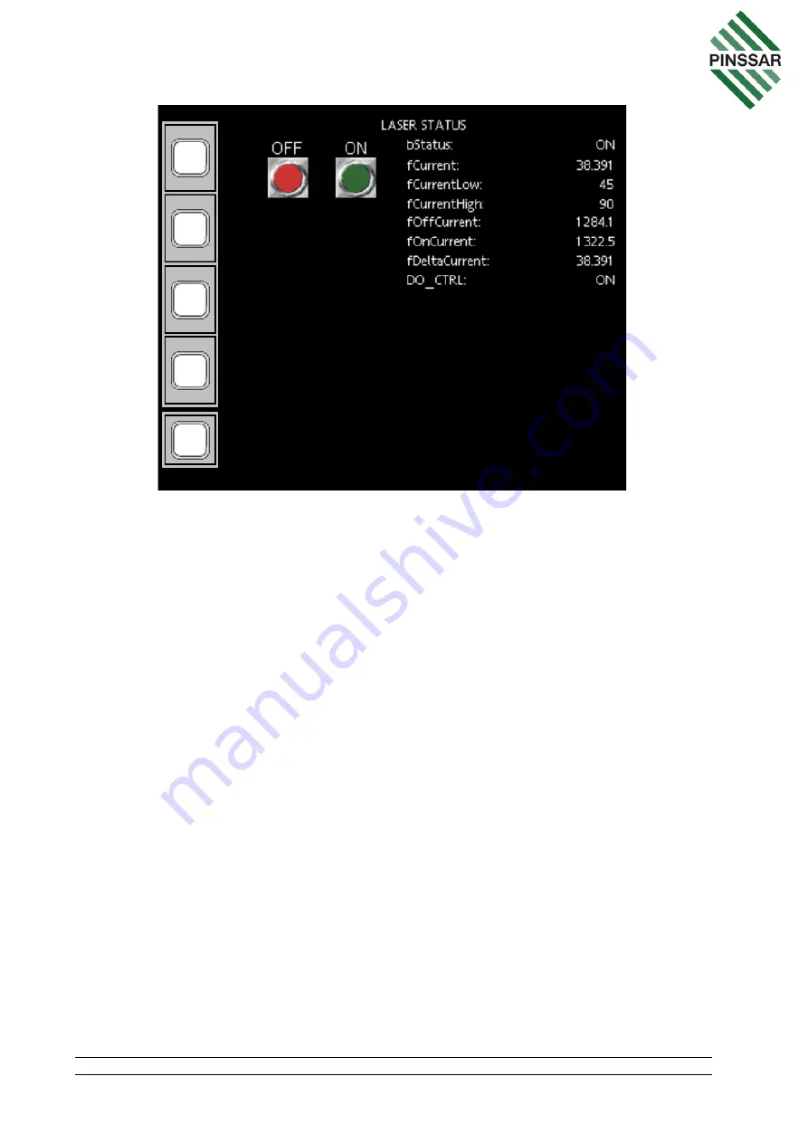
LASER
STATUS
P
AGE
fCurrent on the LASER STATUS page shows the current consumption of the Laser
during the last cycle. Check if the fCurrent is outside of the setpoints limits of
fCurrentLow and fCurrentHigh. Wait for two cycles to complete to see if the issue is
persistent.
If the issue is persistent, the laser can be manually turned on. Firstly, place the DPM
Reader in standby mode as per Section 11.3. Then manually turn on the laser with
green ON button. Turn on the Amplifier and Sensor and check the reported reading of
the Amplifier on the System Overview Page against Table 9. Check the status of relay
No 6 in the Phoenix Contact Relays by confirming the digital output voltage is 5VDC.
Check the connection on DPM carrier board and check the output on DPM carrier board
for the laser.
12.6 Blower
From the SYSTEM OVERVIEW page, clicking on the BLOWER box will take the user
to the BLOWER STATUS page (Figure 60). This will allow operators to monitor and
manually control the state of the Blower motor. If the blower fCurrent or iSpeed reading
is outside of setpoint limits fCurrentLow or fCurrentHigh, the blower status is unhealthy.
If fCurrent is outside of the setpoints wait for two cycles to see if the issue is persistent.
If the issue is persistent, the Blower can be turned on manually after the DPM Reader
has been placed into standby mode as per Section 11.3. Manually turn on the blower
by clicking the green ON button and then the green FASTER button. Check the status
of blower reading on HMI window on SYSTEM OVERVIEW page. Check the voltage