


PIN-M-02 DPMRA01.A Service Manual
Copyright © Pinssar (Aust) Pty Ltd 2019. The PINSSAR logo is a registered trademark of Pinssar Pty Ltd
Page 34 of
96
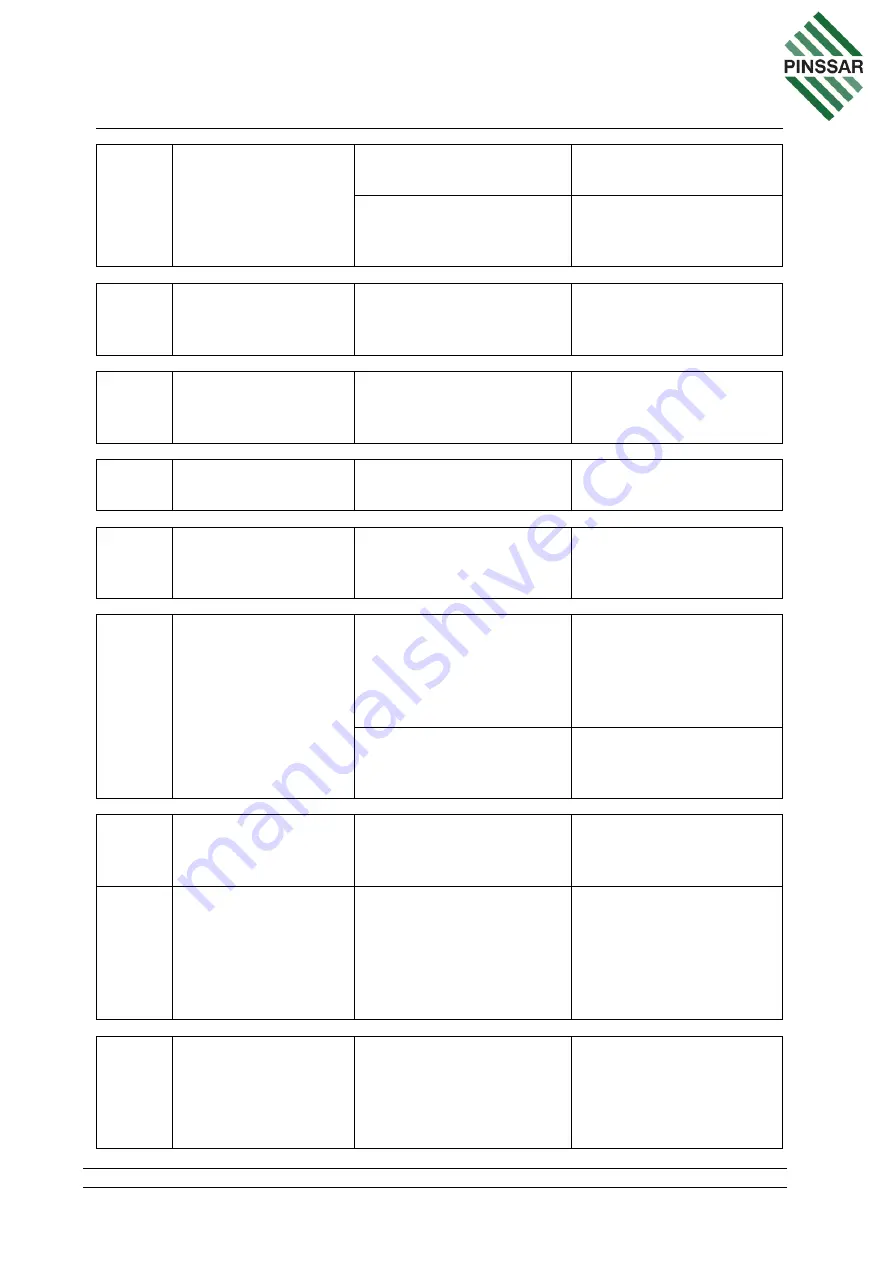
24
Ethernet RJ45
connector
Secure. Gasket in good
condition (external)
Refit, replace gasket if
necessary
Not loose and connected
securely to wireless
modem router (internal)
Firmly re-insert
25
USB connector
Not loose and connected
securely to Red Lion SX
data station (internal)
Firmly re-insert
26
AC Mains input
connector
Not loose and connected
securely to AC isolation
switch
Firmly re-insert
27
Power supply
connector
Pressed in firmly into
AC/DC power supply
Firmly re-insert
28
Power button
Not loose and connected
securely to the AC/DC
Power Distribution Board
Firmly re-insert
29
Battery
Sensor battery to be
firmly secured to
enclosure mounting tray
with bracket fastened
correctly with 2 fasteners
Re-fit seated correctly
and/or remove double-
sided adhesive, clean
and re-apply with new
adhesive
Power connectors
pressed in firmly onto
battery terminals
Firmly re-insert
30
Cellular and Wi-Fi
wireless modem
router
Unit to be firmly secured
to DIN rail
Unlock unit from DIN
rail and firmly re-insert
to DIN rail
31
Cellular and Wi-Fi
wireless modem
router
Power “ON” green LED.
For all other router
states, please refer to
Status table, provided
under Fault Diagnostics,
Router.
Check power
connection to 12VDC
supply Board
32
Axioline F-Bus
coupler for Ethernet
Unit to be firmly secured
to DIN rail
Unlock unit from DIN
rail and firmly re-insert
to DIN rail (ensure pins
to bus bar not bended
and damaged)