


2
0
1
9
-1
0
12
ICE1-*-G60L-V1D, ICE1-*-G60L-C1-V1D
Product Description
2.3
Interfaces and Connections
The contact arrangements below show the front view of the plug-in area of the connectors.
Fieldbus Connection X01, X02
•
Connection: M12 socket, 4 pin, D-coded
•
Color coding: green
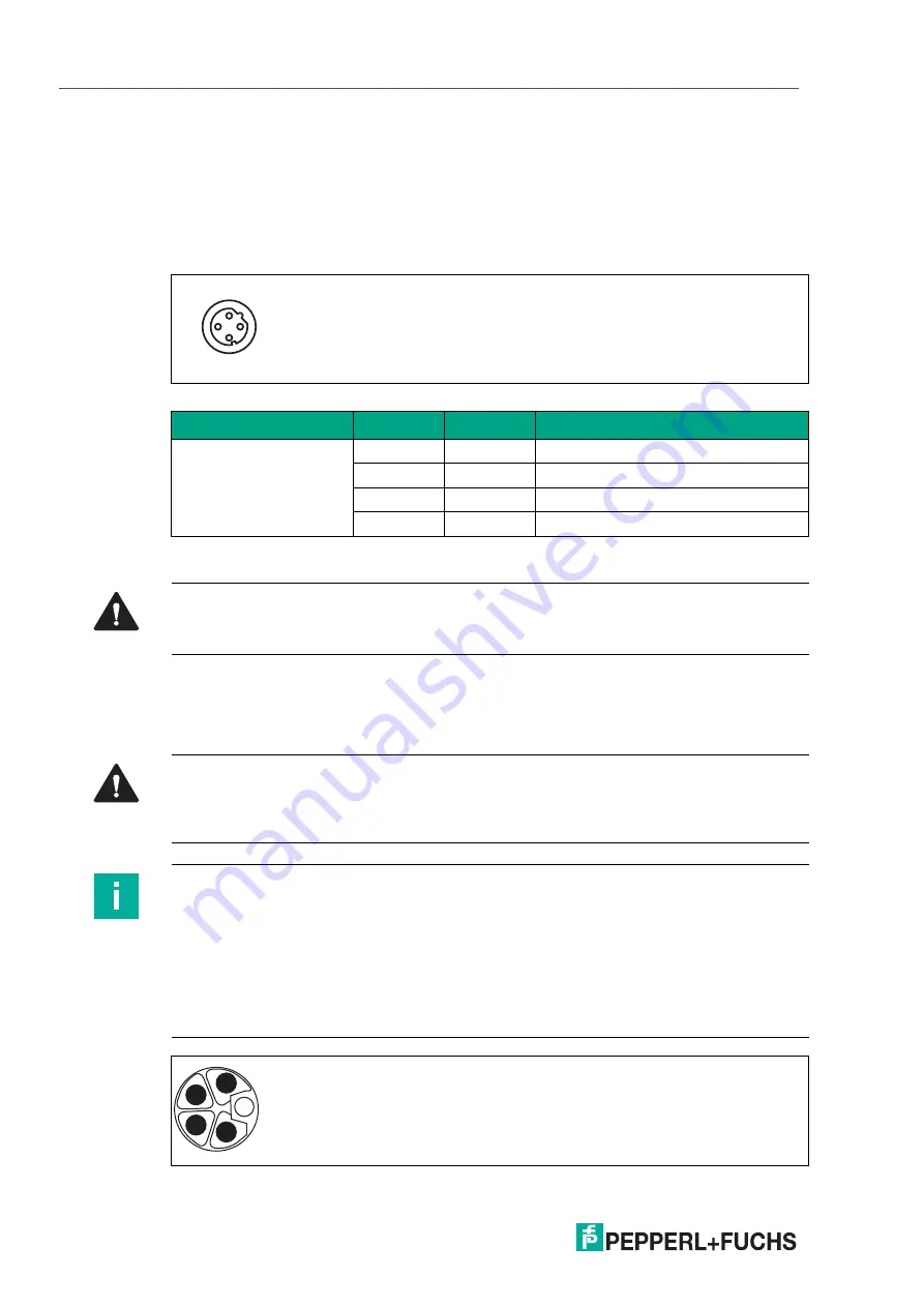
Figure 2.2
Schematic drawing of port X01, X02
Connection for Power Supply X03, X04
•
Power supply with M12 power L-coded
•
Color coding: gray
Figure 2.3
Schematic drawing of M12 L-encoding (plug); port X03 (IN)
Port
Pin
Signal
Function
Ports X01, X02
1
TD+
Transmit data +
2
RD+
Receive data +
3
TD-
Transmit data -
4
RD-
Receive Data -
Table 2.4
Assignment of port X01, X02
1
3
2
4
Caution!
Risk of destruction!
Never route the power supply to the data cable.
Caution!
Loss of function when the system supply voltage is too low.
Ensure in all cases that the supply voltage measured at the most remote participants (sen-
sor/actuator) does not drop below 18 V DC in terms of system supply voltage.
Note
Power supply connection
When connecting the power supply, ensure a separate power supply to the sensor and system
via U
s
and auxiliary supply via U
L
for e.g., actuators. Where the plant has a separate power
supply concept for system current and load current, this means the sensor and system area of
the Ethernet IO module can continue working even if there is a failure of the load power supply.
Where several Ethernet IO modules are connected in series, ensure the separate power
supplies are connected properly U
s
.U
L
.
4
1
3
2
FE


