Wall Mounting Construction
28
Installation Manual
6
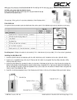
Route and connect the power cable and video
cable, which have already been passed
through the projector arm, to the projector, and
secure the pipe cap (
G
) using the screw (
H
)
for securing the pipe cap.
7
Attach cable holder A (
1
) to the center wall side of
the lift bottom stay, and route the power cable and
video cable so that they point straight down.
•
Use cable holder B (
2
) for cable management of
the elite Panaboard and other equipment.
•
Use the hook and loop fastener (
3
) for cable
management of the computer on the table and
cords connected to the plug adaptor.
Adjusting the Up/Down Unit
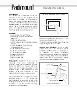
Align the position of the hold tube assembly, to which
the gas spring is secured, with the elite Panaboard
model to be installed, and set it.
•
Adjustment Tolerance:
d
1
Pipe Cap (
G
)
Screw for Securing Pipe Cap (
H
)
Cable Holder A (
1
)
Lift Bottom Stay
Model No.
Adjustment
Position
Model No.
Adjustment
Position
UB-T880W
9
UB-T781
2
UB-T880
7
UB-T780
1.5
UB-T781W
2.5
UB-T780BP
1
Hold Tube Assembly
M6 189 Screw
Arm 450
Gas Spring
Adjustment Position
UE-608030_EN.book 28 ページ 2010年10月28日 木曜日 午後4時20分


