183
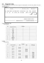
4.8.
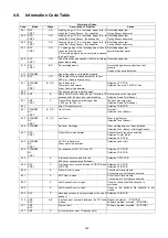
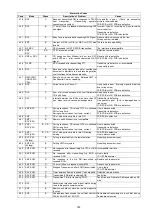
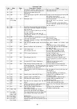
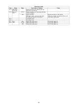
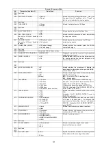
Information Code Table
Information Codes
Code
Mode
Phase
Description of Problem
Cause
001 RCV
COPY
C, D
Leading edge of the recording paper fails to
reach the Timing Sensor. (1st cassette)
Recording paper jam.
Timing Sensor abnormal.
002 RCV
COPY
C, D
Leading edge of the recording paper fails to
reach the Timing Sensor. (2nd cassette)
Recording paper jam.
Timing Sensor abnormal.
003
RCV
COPY
C, D
Leading edge of the recording paper fails to
reach the Timing Sensor. (3rd cassette)
Recording paper jam.
Timing Sensor abnormal.
007 RCV
COPY
C, D
1. Leading edge of the recording paper fails to
reach the Eject Sensor.
2. Recording paper has not completely passed
the Eject Sensor.
Recording paper jam.
Eject Sensor abnormal.
008
RCV
COPY
C, D
Paper Cassette was opened while the recording
paper was feeding.
Recording paper jam.
010
RCV
COPY
B, C
No recording paper.
No recording paper or paper is not set
properly.
No paper Sensor is defective.
011
STANDBY
-
Paper Cassette is not installed properly.
012
RCV
C, D
The length of the received document is over
380 mm. (Used in France only)
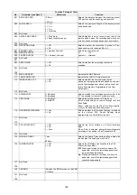
021
STANDBY
RX
COPY
B, C, D
Fan is abnormal.
Thermister is abnormal.
Fuser Control is abnormal.
Defective LPC PCB.
Defective Fuser Unit, LVPS or Fan.
026
-
-
The backup battery is getting weak.
030
XMT
B
Read Point Sensor does not go ON within 10
seconds after the document starts feeding.
Document is not set properly.
Defective Read Point Sensor.
031
XMT
COPY
C
Transmitting document was longer than
2,000 mm (or 78.7 in).
The document may jam.
Defective Read Point Sensor.
033
-
-
Sub CPU system error.
Defective FCB PCB.
041
STANDBY
RX
COPY
B, C, D
Out of toner.
No toner.
Defective Toner Sensor.
043
STANDBY
RX
COPY
B, C, D
Low Toner.
Toner is getting low.
Defective Toner Sensor.
045
STANDBY
-
No Toner Cartridge.
Toner cartridge has not been installed.
Defective Toner Sensor (Cartridge Sensor).
051
RCV
COPY
-
Printer Motor is abnormal.
Connector not properly connected.
Defective Printer Motor.
Defective LPC PCB.
054
STANDBY
RX
COPY
-
HSYNC is abnormal.
Laser motor is abnormal.
Defective Laser Unit.
055
STANDBY
RX
COPY
-
No response of LBP CPU on LPC.
Defective LPC PCB.
Defective FCB PCB.
058
-
A
Interface error occurred with the
500-sheet optional cassette feeder.
Defective CST3 PCB.
059
RCV
COPY
C
Interface error occurred between FCB PCB and
LPC PCB.
Defective LPC PCB.
Defective FCB PCB.
060
-
A
Printer Cover is open.
Cover is not firmly closed.
Connectors are not firmly connected.
061
-
A
ADF Door is open.
Cover is not firmly closed.
Connectors are not firmly connected.
063
-
A
Jam Access Cover is open.
Cover on the optional 2nd cassette is
not closed.
064
-
A
Jam Access Cover is open.
Cover on the optional 3rd cassette is not
closed.
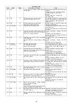
200
RCV
C
Decoding process is not completed at the end of
phase C.
Defective FCB PCB.
212
XMT
RCV
A-E
Interface error occurred between the CPU and
modem.
Modem is defective. (FCB PCB)
Software problem occurred. (FCB PCB)
301
XMT
RCV
-
System fault.
Software problem occurred. (FCB PCB)
331
XMT
C
8-minutes timer error. (Germany only)
Summary of Contents for Panafax DX-2000
Page 2: ......
Page 27: ...27 9 1 Screw 19 10 Release two Latch Hooks 11 Remove the SNS Assembly 121 9 10 11 ...
Page 49: ...49 2 15 Screw Identification Template ...
Page 57: ...57 3 7 3 Option Cassette Circuit 555 748 728 744 928 953 730 731 731 952 944 930 931 931 ...
Page 58: ...58 3 7 4 LAN Control Circuit 522 CN50 1102 1104 1101 N C N C RD N C N C RD TD TD ...
Page 59: ...59 3 7 5 Page Description Language Printer Interface Kit ...

