268
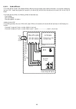
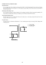
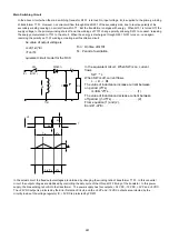
Control Circuit and Error Detection Circuit
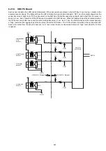
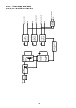
The control circuit amplifies the output of the duty cycle according to the error voltage detected by the Error Detection Circuit,
and drives the main transistor Q101. The method used to change the duty cycle is to change the ON time period. When the
output voltage of the +24 VDC circuit rises, the current of photocoupler PC101 increases, the output pulse width of the control
circuit decreases and the ON time period of Q101 decreases. This control circuit decides the minimum OFF time period by
itself. When the oscillation frequency becomes higher and the OFF time period becomes minimum, the OFF time period
remains unchanged and only the ON time period decreases. This way, there is a upper limit of the oscillation frequency and the
duty cycle is expanded.
Over Current Limiter
The +24 VDC output is limited by Ton MAX Limiter (ON time period of transistor Q101) which is part of the control circuit. The
+5 VP, -12 VDC and +5 VDC outputs have over current limiters provided inside the voltage regulator and IC251.
Summary of Contents for Panafax DX-2000
Page 2: ......
Page 27: ...27 9 1 Screw 19 10 Release two Latch Hooks 11 Remove the SNS Assembly 121 9 10 11 ...
Page 49: ...49 2 15 Screw Identification Template ...
Page 57: ...57 3 7 3 Option Cassette Circuit 555 748 728 744 928 953 730 731 731 952 944 930 931 931 ...
Page 58: ...58 3 7 4 LAN Control Circuit 522 CN50 1102 1104 1101 N C N C RD N C N C RD TD TD ...
Page 59: ...59 3 7 5 Page Description Language Printer Interface Kit ...

