253
6.2.6.
Picture Quality Control Circuit
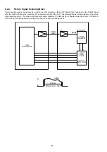
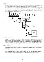
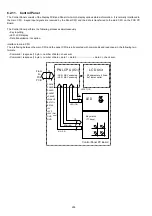
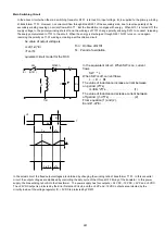
This circuit consists of a recording picture control standard cell IC140 (DZZAC000168 or “1PC”), an interpolation table ROM (IC141)
and its peripheral circuitry.The recording picture control standard cell (IC140) inputs the serial data from the IC110 (DZZAC000167
or “PEC”), conducts picture quality correction (smoothing), reduction, synchronization control, etc., then sends this data to the
printer. These functions are as follows:
Picture quality correction circuit (smoothing)
Compares the picture element with 15 surrounding picture elements, determines the interpolation data from the interpolation
data ROM, and smooths out diagonal lines, etc., on the recorded picture.
Image range isolation circuit
Identifies the halftone picture range and controls smoothing to eliminate blotching of the recording picture which has undergone
error diffusion or other processing.
Reduction circuit
This circuit is used to process the received data so that it fits on the recording paper, according to the Fax Parameter settings.
Synchronization control circuit
This circuit is used to synchronize the output recorded data with the horizontal synchronizing output signal from the printer for
each line. Within a line, it is synchronized with the dot clock signal. The dot clock signal is provided by dividing the crystal
oscillator frequency from the Extend Generator Circuit (32 MHz : 16 x 15.4, 18.117MHz : 600dpi) by 5.
XIN
18.117MHz
32MHz
XOUT
ENB0 4
VDOCK
FEN
HSYNC
VSYNC
VDOCK
VDO
FIFO
I/F
FIFO
I/F
DUDAT
ZA16 0
FCK
FRST
Print
Data
Control
Timing Generator
Circuit
Dot
Convertor
Smoothing
Data
ROM
SYRST
CSLIC
RD
WR
INTRQ
PSDA
PSCK
PSRQ
A5 1
D15 0
System
Bus
Interface
Register
Horizontal
Synchronization
Circuit
ENB0 4
VDOCK
VIDEO
BUNRI
ZD7 0
ZD7 0
(DO7 4)
(DO3 4)
(DI7 5)
(DI3 4)
(DI4)
FDO3 0
FDI3 0
Summary of Contents for Panafax DX-2000
Page 2: ......
Page 27: ...27 9 1 Screw 19 10 Release two Latch Hooks 11 Remove the SNS Assembly 121 9 10 11 ...
Page 49: ...49 2 15 Screw Identification Template ...
Page 57: ...57 3 7 3 Option Cassette Circuit 555 748 728 744 928 953 730 731 731 952 944 930 931 931 ...
Page 58: ...58 3 7 4 LAN Control Circuit 522 CN50 1102 1104 1101 N C N C RD N C N C RD TD TD ...
Page 59: ...59 3 7 5 Page Description Language Printer Interface Kit ...

