255
6.2.9.
Line Control Board
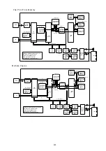
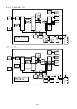
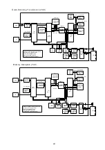
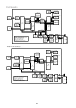
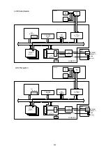
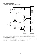
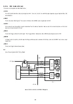
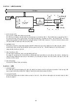
The following shows a block diagram of the Line Control Board.
The Ring Detector consists of a photocoupler, PC2, and its peripheral circuits. The ringing signal is half-wave rectifier in the Ring
Detector, and transferred through the nCTON signal line to the IC60 on the FCB PC Board. The IC60 observes the signal to
distinguish from signals caused by chattering.
The Off-Hook Detector (External Telephone) circuit consists of the photocoupler, PC1, and its peripheral circuits. When PC1
detects loop current flow, it emits a Low active output signal (nHKOF) to the IC60 which monitors it for a specified time. If the IC60
detects no change in the Low signal level, it determines that the External Telephone is Off-Hook.
PC2
PC1
CML
PLS
CML
Line
PC2
PC1
Telephone
Off-Hook
Detector
Ring
Detector
CML
C5
T2
PLS
Modem
(IC 91)
(IC 90)
(IC 80)
Port
(IC 60)
FCB PCB
LCU PCB
+24V
Port
(IC 60)
Port
(IC 60)
Summary of Contents for Panafax DX-2000
Page 2: ......
Page 27: ...27 9 1 Screw 19 10 Release two Latch Hooks 11 Remove the SNS Assembly 121 9 10 11 ...
Page 49: ...49 2 15 Screw Identification Template ...
Page 57: ...57 3 7 3 Option Cassette Circuit 555 748 728 744 928 953 730 731 731 952 944 930 931 931 ...
Page 58: ...58 3 7 4 LAN Control Circuit 522 CN50 1102 1104 1101 N C N C RD N C N C RD TD TD ...
Page 59: ...59 3 7 5 Page Description Language Printer Interface Kit ...

