196
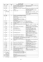
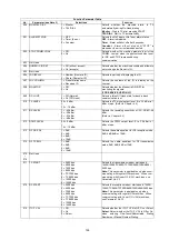
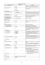
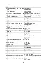
020
ITU-T ECM
1 = Off (Invalid)
2 = On (Valid)
Select the ECM mode.
021
EP TONE
1 = Off (without EP Tone)
2 = On (with EP Tone)
Selects whether to add the echo protect tone on
V.29 mode.
(Used when Echo Suppression is disabled.)
On: Add
Off: Do not add
022
SIGNAL INTERVAL
1 = 100 ms
2 = 200 ms
3 = 500 ms
Selects the time interval between the receiving
signal and the transmitting signal.
023
TCF CHECK
1 = Normal (Short)
2 = Long
Selects the TCF check interval Long/Short
024
CED FREQUENCY
1 = 1080 Hz (non CCITT)
2 = 2100 Hz
Selects the CED frequency 2100/1080 Hz
025
COMM. START-UP
1 = 1’st response
2 = 2’nd response
Selects the communication start-up condition (XMT
and Polling).
(Used when Echo Suppression is disabled.)
026
NON-STANDARD
1 = Off (Invalid)
2 = On (Valid)
Selects own mode (Panafax mode).
027
SHORT PROTOCOL B
1 = Off (Invalid)
2 = On (Valid)
Selects the short protocol mode.
028
SHORT PROTOCOL D
1 = Off (Invalid)
2 = On (Valid)
Selects the short protocol mode.
029
REMOTE DIAGNOSTICS
1 = Off (will not accept)
2 = On (accepts)
Selects whether the machine accepts the Remote
Diagnostics from the service station.
030
CED & 300 bps
1 = 75 ms
2 = 1 sec
Selects the pause interval between the CED and
the 300 bps signal.
(Used when Echo Suppression is disabled.)
031
RTC = EOLx12
1 = Off (EOLx6)
2 = On (EOLx12)
Selects the RTC signal, EOLx6 or EOLx12.
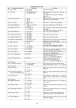
032
V34 TX START
2400-33600bps
Selects the transmission modem start speed for
V.34 communication, 33600-2400 bps.
033
V34 RX START
2400-33600bps
Selects the receiving modem start speed for V.34
communication, 33600-2400 bps.
034
V34 TX Symbol Rate
2400-3429sr
Selects the transmission symbol rate for V.34,
3429/3200/3000/2800/2400 sr.
Press “
∨
“ or “
∧
“ to select the symbol rate.
035
V34 RX Symbol Rate
2400-3429sr
Selects receiving symbol rate for V.34,
3429/3429/3200/3000/2800/2400 sr.
Press “
∨
“ or “
∧
“ to select the symbol rate.
036
Not Used
037
PROTOCOL DISPLAY
1 = Off (not displayed)
2 = On (displayed)
Selects whether to display the modem speed
during communication. (Press “
∨
“ or “
∧
“ to display)
038
Not Used
039
FLASH TIME
5 = 50 ms
~
100 = 1000 ms
Selects the pause interval before activating the
Flash key.
040
E/F TIME (For Germany,
Austria and Switzerland only)
5 = 50 ms
~
100 = 1000 ms
Selects the pause interval before activating the
Flash key.
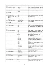
041
PAUSE TIME
1 = 1 sec.
~
10 = 10 sec.
Selects the pause interval from 1 sec. ~ 10 sec. for
dialing through a switchboard or for international
calls.
042
Not Used
043
REDIAL INTERVAL
0 = no waiting
~
15 = 15 minutes
Selects the redial interval from 0 to 15 minutes in 1
minute steps.
044
REDIAL COUNT
0 = no redial
~
15 = 15 times
Selects the redial count from 0 to 15 times in 1 step
intervals.
045
RING DETECT COUNT
1 = 1 ring
~
9 = 9 rings
Selects the ring detection count from 1 to 9 rings in
1 ring step intervals.
046
ON-HOOK TIME
0 = 0 sec.
~
90 = 90 sec.
Selects the on-hook time between sequential
communication calls in 1 second step intervals.
047
RESPONSE WAIT
1 = 1 sec.
~
90 = 90 sec.
Selects the waiting interval for the response after
completing the dialing.
Function Parameter Table
No.
Parameter (see Note 3)
Selections
Function
Summary of Contents for Panafax DX-2000
Page 2: ......
Page 27: ...27 9 1 Screw 19 10 Release two Latch Hooks 11 Remove the SNS Assembly 121 9 10 11 ...
Page 49: ...49 2 15 Screw Identification Template ...
Page 57: ...57 3 7 3 Option Cassette Circuit 555 748 728 744 928 953 730 731 731 952 944 930 931 931 ...
Page 58: ...58 3 7 4 LAN Control Circuit 522 CN50 1102 1104 1101 N C N C RD N C N C RD TD TD ...
Page 59: ...59 3 7 5 Page Description Language Printer Interface Kit ...

