Table of Contents
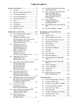
4
Service Modes ....................................... 193
Service Mode Table..............................193
Service Mode 1
(Function Parameter Setting)................194
Service Mode 3
(Printout of Lists,
Reports and Test Results) ...................200
Service Mode 4 (Modem Test) .............215
Service Mode 5 (Diagnostic).................220
Service Mode 6 (RAM Initialization)......222
Service Mode 7 (LBP Service Mode)....223
Service Mode 8 (Check & Call).............224
Service Mode 9
(System Maintenance)..........................229
System Description................................ 234
Mechanical Operation...........................234
Electrical Circuit Explanation ................242
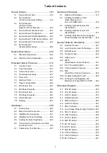
Exploded View & Parts List.................... 272
Country Codes......................................272
Cover Assembly....................................273
Control Panel Unit.................................275
Transmitter Assembly ...........................277
Fuser Unit .............................................279
Electrical Parts......................................281
Paper Transportation ............................284
250 Feeder Unit ....................................287
250 Paper Cassette ..............................289
7.10. 500 Feeder Unit ....................................291
7.11. 500 Paper Cassette ..............................293
7.12. Internet Module.....................................295
7.13. Packing .................................................297
Installation.............................................. 299
Function Key.........................................299
Main Unit and Accessories ...................300
Installing the Accessories .....................301
Installing the Toner Cartridge ...............302
Loading the Recording Paper ...............304
Connecting the Telephone Line Cable
and Power Cord....................................306
Customizing Your Machine...................307
Options and Supplies ............................ 313
Options and Supplies ........................... 313
Installing the Memory Card
(Flash Memory Card
and / or D-RAM Card) .......................... 315
Installing Optional Feeder Unit
(UE-409057)......................................... 316
Installing Optional Feeder Unit
(UE-409056)......................................... 318
Installing Page Description Language
Printer Emulation Kit (UE-403169) ....... 320
General Network Information................. 323
10.1 Network Protocol .................................. 323
10.2 Layer Functions and Technology ......... 325
10.3 Network Layer ...................................... 328
10.4 Transport Layer .................................... 332
10.5 Upper Layer ......................................... 333
(Simple Mail Transfer Protocol)............ 337
10.7 ITU T.37 and RFC2305 ........................ 337
10.8 Communication Protocols .................... 342
(Post Office Protocol Version 3) ........... 345
10.10 Troubleshooting from a PC .................. 348
10.11.Verifying the Configuration and
Mail Account Type (SMTP or POP) ..... 349
Schematic Diagram ............................... 350
11.1. FCB PC Board ..................................... 350
11.2. LCU PC Board ..................................... 374
11.3. LCE PC Board...................................... 375
11.4. LANB PC Board ................................... 376
11.5. FRM PC Board ..................................... 386
11.6. LANC PC Board ................................... 387
11.7. SRU PC Board ..................................... 389
11.8. Low Voltage Power Supply PC Board.. 390
11.9. PNL PC Board...................................... 392
11.10.CCD PC Board ..................................... 396
11.11.LPC PC Board...................................... 397
11.12.SNS PC Board ..................................... 401
11.13.ACI PC Board....................................... 402
11.14.ILS PC Board ....................................... 403
11.15.SSN PC Board ..................................... 404
11.16.CST2 PC Board ................................... 405
11.17.CST3 PC Board ................................... 406
11.18.EP PC Board ........................................ 407
Summary of Contents for Panafax DX-2000
Page 2: ......
Page 27: ...27 9 1 Screw 19 10 Release two Latch Hooks 11 Remove the SNS Assembly 121 9 10 11 ...
Page 49: ...49 2 15 Screw Identification Template ...
Page 57: ...57 3 7 3 Option Cassette Circuit 555 748 728 744 928 953 730 731 731 952 944 930 931 931 ...
Page 58: ...58 3 7 4 LAN Control Circuit 522 CN50 1102 1104 1101 N C N C RD N C N C RD TD TD ...
Page 59: ...59 3 7 5 Page Description Language Printer Interface Kit ...

