2-36
INSTALLATION ORBAN
MODEL
9400
of the L+R HF FR control until the ringing is again at the flattop modula-
tion level will unbalance the ringing at the leading and trailing edge of
the square wave, and necessitate further adjustment of the L+R HF
control. Alternate between these two interactive controls until the peaks
of ringing at both the leading and trailing edges of the square wave are
at the flattop modulation level.
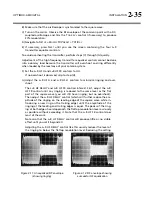
Figure 2-11
illustrates a typical waveform
before adjustment and
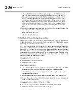
Figure 2-12
shows the result of a successful ad-
justment. (The waveform produced by your system may look quite differ-
ent.)
H)
Turn off the square wave generator and turn off the carrier to allow the
transmitter to cool down for several minutes:
a)
Navigate to
S
ETUP
>
T
EST
.
b)
Set the
M
ODE
to
O
PERATE
.
14.
Set the L–R Transmitter Equalizer controls.
[Skip this step unless you are setting a CQUAM AM stereo facility. The controls
under adjustment in this step do not affect a mono facility if the 9400’s analog
processing chain is set to a mono mode.]
After you have set up the CQUAM exciter for best separation without any audio
processing by following its manufacturer’s instructions, you should trim the
9400’s
L–R
HF
FR
and
L–R
HF
controls to maximize stereo separation through
the entire transmission chain, including the 9400. In most cases, you will maxi-
mize separation if you set these controls to the same settings as their L+R coun-
terparts. However, it may be worthwhile to sweep the system and trim the L–R
controls to maximize separation. To do so:
A)
Navigate to
S
ETUP
>
I/O
C
ALIB
.
B)
Set the
AM
P
ROC
control to
S
TEREO
.
C)
Navigate to
S
ETUP
>
T
EST
.
D)
Set the
M
ODE
to
B
YPASS
.
E)
Connect the output of a sweep generator to one input channel of the 9400
(either left or right). Ground the other channel to minimize crosstalk.
Alternatively, you can use a sweep generator with a digital output and
use the 9400’s digital input.
F)
Set the sweep generator’s output level to produce about 50% modulation.
G)
Observe the output of your CQUAM stereo modulation monitor correspond-
ing to the undriven channel.
H)
Navigate to
S
ETUP
>
M
ODIFY
TX
P
RESET
>
TX1/D
AY
.
I)
Press
N
EXT
until you see the
L–R
HF
FR
and
L–R
HF DELAY controls.
J)
Set these controls the same as their L+R counterparts.
Summary of Contents for Optimod-AM 9400
Page 1: ...Operating Manual OPTIMOD AM 9400 Digital Audio Processor Version 1 2 Software...
Page 7: ...Operating Manual OPTIMOD AM 9400 Digital Audio Processor Version 1 2 Software...
Page 52: ......
Page 204: ......
Page 232: ......
Page 260: ......
Page 261: ...OPTIMOD AM DIGITAL TECHNICAL DATA 6 29...
Page 267: ...OPTIMOD AM DIGITAL TECHNICAL DATA 6 35 CPU Module...
Page 273: ...OPTIMOD AM DIGITAL TECHNICAL DATA 6 41 RS232 BOARD PARTS LOCATOR...
Page 275: ...OPTIMOD AM DIGITAL TECHNICAL DATA 6 43 8300 POWER SUPPLY PARTS LOCATOR...
Page 284: ...6 52 TECHNICAL DATA ORBAN MODEL 9400 DSP BOARD PARTS LOCATOR DRAWING 32170 000 14...
Page 292: ...6 60 TECHNICAL DATA ORBAN MODEL 9400 DISPLAY BOARD PARTS LOCATOR...
Page 293: ...OPTIMOD AM DIGITAL TECHNICAL DATA 6 61 DISPLAY BOARD...

