


OPTIMOD-AM DIGITAL
OPERATION
3-31
Use of a narrow bandwidth, a low boost frequency (like 65 Hz), and a relatively
large boost can produce a very punchy sound in a car, or on a radio with significant
bass response. It can also cost you loudness (bass frequencies take
lots
of modulation
without giving you proportionate perceived loudness), and can result in a thin
sound on radios with only moderate bass response. A smaller amount of boost, a
produce a better compromise.
In
HF broadcast
, perhaps the most difficult of all processing tradeoffs is choosing
bass equalization. This is why the 9400’s a bass equalizer can cut as well as boost.
When propagation conditions are good and the signal strength is high, a certain
amount of bass boost (p3dB) provides the most pleasing sound. However,
robust bass can easily induce intermodulation distortion in the clippers, so the
amount of clipping must be reduced to provide acceptable distortion performance.
In turn, this may compromise loudness by up to 3dB — the equivalent of cutting
transmitter power in half!
Bass boost has a tendency to reduce the life of power tubes in most high-powered
transmitters. It will also tend to induce intermodulation distortion in envelope de-
tectors under selective fading, when detection becomes markedly nonlinear because
of sideband asymmetry. In short, the arguments for bass cut are usually more per-
suasive than those for bass boost. Yet if an HF broadcasting organization seeks the
highest possible subjective quality regardless of transmitter operating cost and feels
that it usually delivers a strong RF signal, free from selective fading, to its listeners,
then such an organization may still wish to boost bass slightly.
It is important to understand that the effect of the bass equalizer is relatively subtle,
because bass balances are also affected by the action of the 150Hz and 420Hz bands
of the multiband limiter and multiband distortion-canceling clipper. These bands will
tend to make bass balances more uniform (partially ``fighting'' bass-balance changes
made with the bass equalizer) by increasing bass in program material that is thin-
sounding, and by limiting heavy bass to a user-settable threshold below 100%
modulation to prevent disturbing intermodulation between bass and higher-
frequency program material. Compared to the 9400’s presets for MW broadcasting,
in the HF presets the threshold of limiting of the 150Hz band has been lowered so
that more gain reduction (and thus, less bass) is produced.
The multiband distortion-canceling clipper prevents hard-clipped bass square waves
from appearing at OPTIMOD-AM's output. Older transmitters will respond better to
this well-controlled, benign waveform than to the hard-clipped bass square waves
produced by less sophisticated processing.
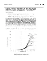
The equalizer, like the classic Orban analog parametrics such as the 622B,
has constant “Q” curves. This means that the cut curves are narrower
than the boost curves. The width (in octaves) is calibrated with reference
to 10 dB boost. As you decrease the amount of EQ gain (or start to cut),
the width in octaves will decrease. However, the “Q” will stay constant.
“Q” is a mathematical parameter that relates to how fast ringing damps
out. (Technically, we are referring to the “Q” of the poles of the equal-
izer transfer function, which does not change as you adjust the amount
of boost or cut.)
Summary of Contents for Optimod-AM 9400
Page 1: ...Operating Manual OPTIMOD AM 9400 Digital Audio Processor Version 1 2 Software...
Page 7: ...Operating Manual OPTIMOD AM 9400 Digital Audio Processor Version 1 2 Software...
Page 52: ......
Page 204: ......
Page 232: ......
Page 260: ......
Page 261: ...OPTIMOD AM DIGITAL TECHNICAL DATA 6 29...
Page 267: ...OPTIMOD AM DIGITAL TECHNICAL DATA 6 35 CPU Module...
Page 273: ...OPTIMOD AM DIGITAL TECHNICAL DATA 6 41 RS232 BOARD PARTS LOCATOR...
Page 275: ...OPTIMOD AM DIGITAL TECHNICAL DATA 6 43 8300 POWER SUPPLY PARTS LOCATOR...
Page 284: ...6 52 TECHNICAL DATA ORBAN MODEL 9400 DSP BOARD PARTS LOCATOR DRAWING 32170 000 14...
Page 292: ...6 60 TECHNICAL DATA ORBAN MODEL 9400 DISPLAY BOARD PARTS LOCATOR...
Page 293: ...OPTIMOD AM DIGITAL TECHNICAL DATA 6 61 DISPLAY BOARD...