3-56
OPERATION ORBAN
MODEL
9400
emphasis). If you use the digital radio output to feed a digital channel with pre-
emphasis, you must allow extra headroom to compensate for the unpredictable
peak level changes that the pre-emphasis induces.
If the digital radio output is driving a channel without pre-emphasis, it will control
peak levels with an uncertainty of less than 1 dB. However, you may want to allow
headroom to compensate for data reduction-induced peak overshoots at the re-
ceiver, which might otherwise cause clipping. In our experience, 2 dB of headroom is
typically adequate.
All of the 9400’s digital and analog outputs can be switched independently to emit
either the digital radio processed signal or the analog-processed signal.
Delay Difference between Digital-Channel and AM Outputs
In order to make the receiver analog/digital cross-fade without comb filtering, the
time delays in the HD Radio’s analog and digital channels must have a fixed and
predictable offset, correctly implementing the HD Radio receiver’s “time diversity”
processing. The 9400’s digital radio output’s delay is automatically adjusted so that it
always exactly 5.778 ms longer than the AM output’s delay, regardless of the AM
output’s delay (which can vary depending on processing settings). Therefore, the HD
Radio exciter should be set to compensate for this 5.778 ms offset between the AM
output and digital radio output. Once you have done this, the time diversity delay
will always be correct even if you choose a different 9400 preset.
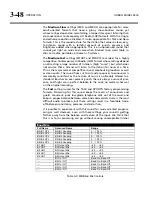
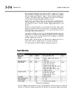
Digital Radio I/O Setup Controls
Monitoring
Meter Sel
determines whether the multimeters (the rightmost pair of meters) show
the instantaneous peak output of the processed audio in units of percentage modu-
lation or the gain reduction of the look-ahead limiter in the digital channel, in units
of dB.
These meters can be switched to read the left/right digital processing chain output
signal, the gain reductions of the left and right look-ahead limiters in the digital
Section Label
Control Name
Values
Monitoring
Meter Sel
AMOutLevel/HDOutLevel/HD GR
Analog Outputs
Out Source
AM /HD/Monitor
Out Level
–6… +20 dBu
Digital Outputs
Out Level
0… –20 dBFS; 0.1 dB steps
Samp Rate
32kHz/44.1kHz/48/88.2/96 kHz
Word Leng
14/16/18/20/24 bits
Dither In/Out
Sync Internal/Sync
In
Format AES/SPDIF
Stereo/Mono Mode
St./Mono Stereo/MonoL/MonoR/MonoL+R
Table 3-11: Digital Radio I/O Setup Controls
Summary of Contents for Optimod-AM 9400
Page 1: ...Operating Manual OPTIMOD AM 9400 Digital Audio Processor Version 1 2 Software...
Page 7: ...Operating Manual OPTIMOD AM 9400 Digital Audio Processor Version 1 2 Software...
Page 52: ......
Page 204: ......
Page 232: ......
Page 260: ......
Page 261: ...OPTIMOD AM DIGITAL TECHNICAL DATA 6 29...
Page 267: ...OPTIMOD AM DIGITAL TECHNICAL DATA 6 35 CPU Module...
Page 273: ...OPTIMOD AM DIGITAL TECHNICAL DATA 6 41 RS232 BOARD PARTS LOCATOR...
Page 275: ...OPTIMOD AM DIGITAL TECHNICAL DATA 6 43 8300 POWER SUPPLY PARTS LOCATOR...
Page 284: ...6 52 TECHNICAL DATA ORBAN MODEL 9400 DSP BOARD PARTS LOCATOR DRAWING 32170 000 14...
Page 292: ...6 60 TECHNICAL DATA ORBAN MODEL 9400 DISPLAY BOARD PARTS LOCATOR...
Page 293: ...OPTIMOD AM DIGITAL TECHNICAL DATA 6 61 DISPLAY BOARD...

