4-10
MAINTENANCE ORBAN
MODEL
9400
D)
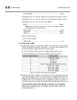
Inject the Analog Input XLR connector with a level of +10 dBu with the oscilla-
tor set to 100 Hz.
E)
Connect the audio analyzer to the 9400's Left Analog Output XLR connector.
F)
Verify a level of +10 dBu ±1 dB. Use this level as the reference level.
G)
Verify that frequency response at 50 Hz, 100 Hz, 400 Hz, 5 kHz, and 15 kHz is
within ±0.1 dB of the reference level.
This procedure tests the analog input circuitry, the A/D converter, the
DSP, the DAC, and the analog output circuitry.
H)
Repeat steps (C) through (G) for the right channel.
5.
Check distortion performance of Analog I/O.
A)
Verify 9400 software controls are set to their default settings. (Refer to page
4-7.)
B)
Be sure you are still in
B
YPASS
mode [see step (3.F)].
C)
Connect a THD analyzer to the Left Analog Output #1 XLR connector. Set the
THD analyzer's bandwidth to 22 kHz.
D)
Connect the oscillator to the Left Analog Input XLR connector.
E)
For each frequency used to measure THD, adjust the output level of the oscil-
lator to make the
C
OMP
meter on the 9400 read
100
.
F)
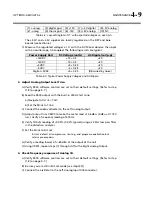
Measure the THD+N at the frequency levels listed below.
Frequency
THD+N Typical
THD+N Maximum
50 Hz
0.015%
0.03%
100 Hz
0.015%
0.03%
400 Hz
0.015%
0.03%
1 kHz
0.015%
0.03%
2.5 kHz
0.015%
0.03%
5 kHz
0.015%
0.03%
7.5 kHz
0.015%
0.03%
15 kHz
0.015%
0.03%
G)
Repeat the above measurements for the right channel. Connect the oscillator
to the right analog input and the distortion analyzer to the right analog out-
put.
H)
Repeat these measurements for the left and right channels of Analog Output
#2.
I)
Disconnect the oscillator and THD analyzer from the 9400.
6.
Test Digital Sample Rate Converter (Receiver).
A)
Verify 9400 software controls are set to their default settings. (Refer to page
4-7.)
Summary of Contents for Optimod-AM 9400
Page 1: ...Operating Manual OPTIMOD AM 9400 Digital Audio Processor Version 1 2 Software...
Page 7: ...Operating Manual OPTIMOD AM 9400 Digital Audio Processor Version 1 2 Software...
Page 52: ......
Page 204: ......
Page 232: ......
Page 260: ......
Page 261: ...OPTIMOD AM DIGITAL TECHNICAL DATA 6 29...
Page 267: ...OPTIMOD AM DIGITAL TECHNICAL DATA 6 35 CPU Module...
Page 273: ...OPTIMOD AM DIGITAL TECHNICAL DATA 6 41 RS232 BOARD PARTS LOCATOR...
Page 275: ...OPTIMOD AM DIGITAL TECHNICAL DATA 6 43 8300 POWER SUPPLY PARTS LOCATOR...
Page 284: ...6 52 TECHNICAL DATA ORBAN MODEL 9400 DSP BOARD PARTS LOCATOR DRAWING 32170 000 14...
Page 292: ...6 60 TECHNICAL DATA ORBAN MODEL 9400 DISPLAY BOARD PARTS LOCATOR...
Page 293: ...OPTIMOD AM DIGITAL TECHNICAL DATA 6 61 DISPLAY BOARD...

