


OPTIMOD-AM DIGITAL
INTRODUCTION
1-15
limits on occupied bandwidth specified by the governing authority and will greatly
degrade the spectral control provided by OPTIMOD-AM.
To achieve the full performance capability built into OPTIMOD-AM, any filters in the
transmitter must be bypassed. This is essential! OPTIMOD-AM contains low-pass and
high-pass filters that are fully capable of protecting the transmitter and controlling
occupied bandwidth. Because of their location within OPTIMOD-AM, the internal
filters do not introduce spurious modulation peaks.
Any built-in peak clippers in the transmitter should be defeated. OPTIMOD-AM con-
tains a clipping system that is fully capable of controlling transmitter modulation
without introducing out-of-band energy. If the drive level to the transmitter is even
slightly excessive, the transmitter clipper will be driven hard enough to create exces-
sive spurious spectrum. Defeating any clippers in the transmitter prevents this possi-
bility.
This problem will be even worse if OPTIMOD-AM's transmitter equalizer is in use.
OPTIMOD-AM's output level will frequently exceed 100% modulation because it is
pre-distorted to complement the transmitter's pulse response. The transmitter's
built-in safety clipper will surely clip this pre-distorted waveform.
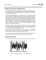
Power Supplies
An AM transmitter is required to provide 150% of equivalent unmodulated carrier
power when it is modulating 100%. High-voltage power supplies are subject to two
major problems: sag and resonance.
Sag is a result of inadequate steady-state regulation. It causes the conventional car-
rier shift that is seen on a modulation monitor. Good transmitter engineering prac-
tice usually limits this shift to -5% (which corresponds to about 0.5dB not a highly
significant loudness loss).
A more serious problem is dynamic carrier shift, or bounce. This has been known to
cause up to 3dB loudness loss. Resonances in the power supply's LC filter network
usually cause it. Any LC network has a resonant frequency. In order to achieve rea-
sonable efficiency, the power supply filter network must be under-damped. There-
fore, high modulation excites this resonance, which can cause overmodulation on
the low-voltage peaks of the resonance.
Curing bounce is not at all straightforward because of the requirement that the
power supply filter smooth the DC sufficiently to achieve low hum. One approach
that has been employed is use of a 12-phase power supply. Upon rectification, the
ripple component of the DC is down about -40dB without filtering. A single-
capacitor filter can thus be used, eliminating the filter inductor as a potential source
of resonance with the capacitor.
Other sources of resonance include the modulation reactor and modulation trans-
former in conventional plate-modulated transmitters. Such transmitters will not
greatly benefit from a 12-phase power supply.
Summary of Contents for Optimod-AM 9400
Page 1: ...Operating Manual OPTIMOD AM 9400 Digital Audio Processor Version 1 2 Software...
Page 7: ...Operating Manual OPTIMOD AM 9400 Digital Audio Processor Version 1 2 Software...
Page 52: ......
Page 204: ......
Page 232: ......
Page 260: ......
Page 261: ...OPTIMOD AM DIGITAL TECHNICAL DATA 6 29...
Page 267: ...OPTIMOD AM DIGITAL TECHNICAL DATA 6 35 CPU Module...
Page 273: ...OPTIMOD AM DIGITAL TECHNICAL DATA 6 41 RS232 BOARD PARTS LOCATOR...
Page 275: ...OPTIMOD AM DIGITAL TECHNICAL DATA 6 43 8300 POWER SUPPLY PARTS LOCATOR...
Page 284: ...6 52 TECHNICAL DATA ORBAN MODEL 9400 DSP BOARD PARTS LOCATOR DRAWING 32170 000 14...
Page 292: ...6 60 TECHNICAL DATA ORBAN MODEL 9400 DISPLAY BOARD PARTS LOCATOR...
Page 293: ...OPTIMOD AM DIGITAL TECHNICAL DATA 6 61 DISPLAY BOARD...