


2-26
INSTALLATION ORBAN
MODEL
9400
6.
Adjust the Digital Input Reference Level and Right Balance controls.
[Skip this step if you will not be using the digital input.]
A)
Navigate to
S
ETUP
>
IO
C
ALIB
>
I
NPUT
>
D
IG
I
N
and set the input source to Digi-
tal.
B)
Repeat steps 3 through 5 (starting on page 2-23), but use the
DI
R
EF
(VU
OR
PPM)
and
R
CH
BAL
controls for the digital section.
7.
Set output bandwidth and highpass filter cutoff frequency.
A)
Navigate to
S
ETUP
>
M
ODIFY
T
R
P
RESET
>
TX1/D
AY
.
To describe their most common application, the four transmission presets
are labeled TX1/DAY, TX1/NIGHT, TX2/DAY, and TX2/NIGHT, although
they can be applied in a completely general way to the requirements of
your transmission facility. Transmission Presets can be recalled by remote
control (GPI or PC Remote) and/or at preset times by the 9400’s clock-
based automation.
TX1/DAY
is the default transmission preset and many
stations will always use it once they have set it up.
The controls within a given transmission preset include lowpass filter
cutoff frequency, lowpass filter shape, highpass filter cutoff frequency,
positive peak threshold (asymmetry), and six transmitter equalizer con-
trols.
Only one transmission preset can be active at a given time; that preset
determines the parameters applied to all analog AM processed outputs.
Transmission Presets do not affect any output emitting the HD-processed
signal.
Once you have selected a transmission preset, that preset will be active
until you explicitly select another via the front panel, remote control, or
clock-based automation. This is true even if AC power is interrupted.
However, if clock-based automation was scheduled to recall a different
preset during the period when the 9400 was powered down, upon
power-up the 9400 will automatically recall the preset that would have
been on-air at that time if power had stayed on.
B)
Hold down the soft key under
L
OWPASS
and
S
elect the desired lowpass filter
cutoff frequency by turning the knob.
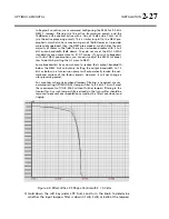
Lowpass filter cutoff frequencies range from 4.5 kHz to 9.5 kHz (NRSC) in
0.5 kHz steps. The setting of the lowpass filter controls your RF occupied
bandwidth, so it is very important to set it to meet the government stan-
dards in your country.
Note that the user processing presets can only lower the low-pass cutoff
frequency below its setting in active transmission preset. If, in the EQ sec-
tion of the processing preset, you exceed the lowpass cutoff frequency of
the TX preset, the TX preset setting will always determine the actual cut-
off frequency of the processor. For example, if you have set the low-pass
cutoff frequency in the active transmission preset to 6.5 kHz, this can be
lowered to 6.0 kHz or below in a processing preset, but not raised above
6.5 kHz. This is to prevent accidentally creating presets that violate the
occupied bandwidth standards of your governing authority.
Summary of Contents for Optimod-AM 9400
Page 1: ...Operating Manual OPTIMOD AM 9400 Digital Audio Processor Version 1 2 Software...
Page 7: ...Operating Manual OPTIMOD AM 9400 Digital Audio Processor Version 1 2 Software...
Page 52: ......
Page 204: ......
Page 232: ......
Page 260: ......
Page 261: ...OPTIMOD AM DIGITAL TECHNICAL DATA 6 29...
Page 267: ...OPTIMOD AM DIGITAL TECHNICAL DATA 6 35 CPU Module...
Page 273: ...OPTIMOD AM DIGITAL TECHNICAL DATA 6 41 RS232 BOARD PARTS LOCATOR...
Page 275: ...OPTIMOD AM DIGITAL TECHNICAL DATA 6 43 8300 POWER SUPPLY PARTS LOCATOR...
Page 284: ...6 52 TECHNICAL DATA ORBAN MODEL 9400 DSP BOARD PARTS LOCATOR DRAWING 32170 000 14...
Page 292: ...6 60 TECHNICAL DATA ORBAN MODEL 9400 DISPLAY BOARD PARTS LOCATOR...
Page 293: ...OPTIMOD AM DIGITAL TECHNICAL DATA 6 61 DISPLAY BOARD...