


2-14
INSTALLATION ORBAN
MODEL
9400
If you are using Orban 8200ST external AGC
If the STL uses pre-emphasis, its input pre-emphasis network will probably introduce
overshoots that will increase peak modulation without any increase in average
modulation. We therefore strongly recommend that the STL transmitter’s pre-
emphasis be defeated (freeing the STL from such potential overshoot), and that the
8200ST be used to provide the necessary pre-emphasis.
If the STL transmitter’s pre-emphasis cannot be defeated, then configure the 8200ST
for flat output. In this case, average modulation levels of the STL may have to be re-
duced to accommodate the overshoots.
1.
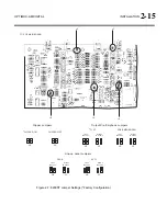
Configure the 8200ST’s internal jumpers.
A)
Remove all screws holding the 8200ST’s cover in place; then lift it off.
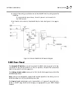
Refer to
Figure 2-7
on page 2-15.
B)
Place jumper JA in the
C
LIPPER
O
N
position.
C)
If you have defeated the STL transmitter’s pre-emphasis, place jumpers JE and
JF in the
P
RE
-E
MPHASIZED
position.
D)
If you cannot defeat the STL transmitter’s pre-emphasis, place jumpers JE and
JF in the
F
LAT
position.
E)
Replace the top cover, and then replace all screws snugly. (Be careful not to
strip the threads by fastening the screws too tightly.)
2.
Install the 8200ST in the rack. Connect the 8200ST’s audio input and out-
put.
Refer to the
8200ST Operating Manual
if you require information about installa-
tion, audio input, and audio output connections to the 8200ST.
3.
Set 8200ST Output Level with tone.
A)
Press the TONE button on the 8200ST.
The TONE lamp should light and the modulation meters should indicate
“0.” If they do not, re-strap jumpers JB and JC to “peak.” (Refer to Figure
2-7 on page 2-15.)
The 8200ST is now producing a 400Hz sine wave at each output. The
peak level of this tone corresponds to 100% modulation.
B)
Adjust the 8200ST’s
L
O
UT
and
R
O
UT
controls so that the STL transmitter is be-
ing driven to 100% modulation.
The
L
O
UT
and
R
O
UT
controls are now correctly calibrated to the transmit-
ter. If no significant overshoot occurs in the transmitter, the
MODULATION
meter will now give an accurate indication of peak modulation of the
STL.
Summary of Contents for Optimod-AM 9400
Page 1: ...Operating Manual OPTIMOD AM 9400 Digital Audio Processor Version 1 2 Software...
Page 7: ...Operating Manual OPTIMOD AM 9400 Digital Audio Processor Version 1 2 Software...
Page 52: ......
Page 204: ......
Page 232: ......
Page 260: ......
Page 261: ...OPTIMOD AM DIGITAL TECHNICAL DATA 6 29...
Page 267: ...OPTIMOD AM DIGITAL TECHNICAL DATA 6 35 CPU Module...
Page 273: ...OPTIMOD AM DIGITAL TECHNICAL DATA 6 41 RS232 BOARD PARTS LOCATOR...
Page 275: ...OPTIMOD AM DIGITAL TECHNICAL DATA 6 43 8300 POWER SUPPLY PARTS LOCATOR...
Page 284: ...6 52 TECHNICAL DATA ORBAN MODEL 9400 DSP BOARD PARTS LOCATOR DRAWING 32170 000 14...
Page 292: ...6 60 TECHNICAL DATA ORBAN MODEL 9400 DISPLAY BOARD PARTS LOCATOR...
Page 293: ...OPTIMOD AM DIGITAL TECHNICAL DATA 6 61 DISPLAY BOARD...