3-44
OPERATION ORBAN
MODEL
9400
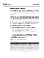
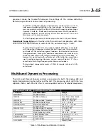
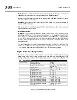
One of the essential differences between the
H
ARD
and
LLH
ARD
bass clip-
per modes is that switching between
H
ARD
and
M
ED
does not change de-
lay and is therefore less likely to cause audible clicks.
The
H
ARD
C
LIP
S
HAPE
control (in Advanced Control) offers further control
over the sound of the
H
ARD
and
LLH
ARD
modes. See page 3-44.
M
EDIUM
uses more sophisticated signal processing than
H
ARD
to reduce distortion
substantially.
S
OFT
uses the most sophisticated look-ahead signal processing to reduce distor-
tion further. Using
S
OFT
adds an additional 18 ms of delay to the processing.
M
EDIUM
and
SOFT
are not available in Low Latency mode. The bass clip-
ping is always
H
ARD
, but the
H
ARD
C
LIP
S
HAPE
control is still available to
“soften” the clipping.
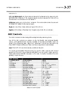
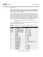
Speech Bass Clip
set the threshold of the bass clipper when the 9400 detects the
presence of speech. It is usually set to “0” to prevent the bass clipper from adding
distortion on speech.
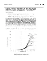
Clip Shape
(“Bass Clip Shape”) allows you to change shape of the knee of the In-
put/Output gain curve of the bass clipper. The “knee” is the transition between no
clipping and flat topping. A setting of “0” provides the hardest knee. “10” is the
softest knee, where the transition starts 6 dB below
B
ASS
C
LIP
T
HRESHOLD
setting and
occurs gradually. The factory default setting is “7.6.”
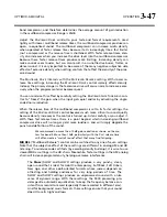
HF CLIP
(“High Frequency Clipper Threshold”; AM chain only) sets the threshold of
the multiband clipper in band 5 with reference to the final clipper threshold, in dB.
This clipper helps prevent distortion in the final clipper when the input program ma-
terial contains excessive energy above 3 kHz.
The Band 5 multiband clipper operates at 256 kHz and is fully anti-aliased.
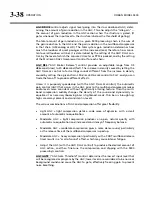
Final Clip
(“Final Clip Drive”) adjusts the level of the audio driving the back-end
clipping system that OPTIMOD-AM uses to control fast peaks. This control primarily
determines the loudness / distortion trade-off.
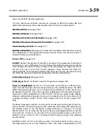
Turning up the
F
INAL
C
LIP
control drives the final clipper and overshoot compensator
harder, reducing the peak-to-average ratio, and increasing the loudness on the air.
When the amount of clipping is increased, the audible distortion caused by clipping
also increases. Although lower settings of the
F
INAL
C
LIP
control reduce loudness,
they make the sound cleaner.
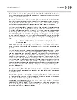
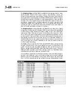
If the
R
ELEASE
control is set to its faster settings, the distortion produced by the
back-end clipping system will increase as the
M
ULTIBAND
D
RIVE
control is advanced.
The
F
INAL
C
LIP
D
RIVE
and/or the
M
ULTIBAND
L
IMIT
T
HRESHOLD
controls may have to be
turned down to compensate. To best understand how to make loudness / distortion
trade-offs, perhaps the wisest thing to do is to recall a factory preset and then to ad-
just the
L
ESS
-M
ORE
control to several settings throughout its range. At each setting
of the
L
ESS
-M
ORE
control, examine the settings of the
M
ULTIBAND
D
RIVE
and
M
ULTIBAND
L
IMIT
T
HRESHOLD
controls. This way, you can see how the factory pro-
Summary of Contents for Optimod-AM 9400
Page 1: ...Operating Manual OPTIMOD AM 9400 Digital Audio Processor Version 1 2 Software...
Page 7: ...Operating Manual OPTIMOD AM 9400 Digital Audio Processor Version 1 2 Software...
Page 52: ......
Page 204: ......
Page 232: ......
Page 260: ......
Page 261: ...OPTIMOD AM DIGITAL TECHNICAL DATA 6 29...
Page 267: ...OPTIMOD AM DIGITAL TECHNICAL DATA 6 35 CPU Module...
Page 273: ...OPTIMOD AM DIGITAL TECHNICAL DATA 6 41 RS232 BOARD PARTS LOCATOR...
Page 275: ...OPTIMOD AM DIGITAL TECHNICAL DATA 6 43 8300 POWER SUPPLY PARTS LOCATOR...
Page 284: ...6 52 TECHNICAL DATA ORBAN MODEL 9400 DSP BOARD PARTS LOCATOR DRAWING 32170 000 14...
Page 292: ...6 60 TECHNICAL DATA ORBAN MODEL 9400 DISPLAY BOARD PARTS LOCATOR...
Page 293: ...OPTIMOD AM DIGITAL TECHNICAL DATA 6 61 DISPLAY BOARD...


