OPTIMOD-AM DIGITAL
OPERATION
3-59
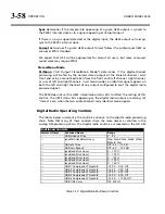
tabs in the 9400 PC Remote application.
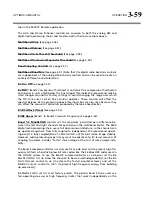
The AGC and Stereo Enhancer controls are common to both the analog AM and
digital radio processing chains and are discussed in their own sections above.
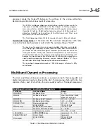
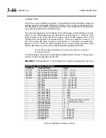
Multiband Drive
(See page 3-46.)
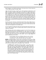
Multiband Release
(See page 3-47.)
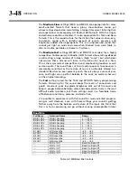
Multiband Gate Thresh (Threshold)
(See page 3-49.)
Multiband Downward Expander Threshold
(See page 3-50.)
Band Coupling Controls
(See page 3-51.)
Multiband Band Mix
(See page 3-51.) Note that the digital radio band mix controls
are independent of the analog AM band mix controls and can be used to create an
entirely different sound coloration.
Bx On / Off
(see page 3-52).
Bx THR
(“Band x Compression Threshold”) controls set the compression threshold in
each band, in units of dB below the final clipper threshold. We recommend making
small changes around the factory settings to avoid changing the range over which
the
HD
L
OOK
-
AHEAD
L
IMITER
D
RIVE
control operates. These controls will affect the
spectral balance of the processing above threshold, but are also risky because they
can affect the amount of distortion produced by the look-ahead limiter.
B1-B5 Attack (Time)
(See page 3-52).
B1/B2 Xover
(Band 1 to Band 2 Crossover Frequency; see page 3-53).
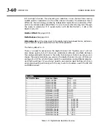
Band 1-5 MaxDeltGR
controls set the maximum permitted gain difference be-
tween the left and right channels for each band in the multiband limiter. The 9400
digital radio processing chain uses a full dual-mono architecture, so the channels can
be operated anywhere from fully coupled to independent. We recommend operat-
ing band 1-4 fully coupled (
B
AND
1-4
M
AX
D
ELT
GR
= 0) for best stereo image stability.
However, audio-processing experts may want to experiment with lesser amounts of
coupling to achieve a wider, “fatter” stereo image at the cost of some image insta-
bility.
The Band 5 compressor/limiter is mainly useful as a de-esser and to prevent high fre-
quency artifacts when driving low bit rate codecs like the 36 kbps HDC codec used in
the HD AM system. To use the Band 5 compressor/limiter as a de-esser, set the
B5
M
AX
D
ELT
GR
to
O
FF
(
to allow the channels to be de-essed independently), set the
B5
D
ELTA
R
ELEASE
control to +6 (to achieve the fastest possible release), and set the
B4>B5
C
OUPLING
control to
100%
(to prevent high frequency energy from building
up excessively).
B5
M
AX
D
ELT
GR
is set
O
FF
most factory presets. This permits band 5 to be used as a
fast-operating de-esser or high frequency limiter that works independently on the
Summary of Contents for Optimod-AM 9400
Page 1: ...Operating Manual OPTIMOD AM 9400 Digital Audio Processor Version 1 2 Software...
Page 7: ...Operating Manual OPTIMOD AM 9400 Digital Audio Processor Version 1 2 Software...
Page 52: ......
Page 204: ......
Page 232: ......
Page 260: ......
Page 261: ...OPTIMOD AM DIGITAL TECHNICAL DATA 6 29...
Page 267: ...OPTIMOD AM DIGITAL TECHNICAL DATA 6 35 CPU Module...
Page 273: ...OPTIMOD AM DIGITAL TECHNICAL DATA 6 41 RS232 BOARD PARTS LOCATOR...
Page 275: ...OPTIMOD AM DIGITAL TECHNICAL DATA 6 43 8300 POWER SUPPLY PARTS LOCATOR...
Page 284: ...6 52 TECHNICAL DATA ORBAN MODEL 9400 DSP BOARD PARTS LOCATOR DRAWING 32170 000 14...
Page 292: ...6 60 TECHNICAL DATA ORBAN MODEL 9400 DISPLAY BOARD PARTS LOCATOR...
Page 293: ...OPTIMOD AM DIGITAL TECHNICAL DATA 6 61 DISPLAY BOARD...

