


4-8
MAINTENANCE ORBAN
MODEL
9400
DO #2 FORMAT................................................................................AES3
e)
Navigate to
S
ETUP
>
IO
C
ALIB
>
AM
P
ROC
. Set the
AM
P
ROC
mode to
S
TEREO
.
f)
Navigate to
S
ETUP
>
IO
C
ALIB
>
HD
P
ROC
. Set the
HD
P
ROC
mode to
S
TEREO
.
g)
Navigate to
S
ETUP
>
T
EST
.
Set controls as follows:
MODE ........................................................................................... Bypass
NOTE:
Bypass defeats all compression, limiting, and program equaliza-
tion, providing a “flat” bypass channel.
BYPASS GAIN ....................................................................................0 dB
TONE FREQ....................................................................................400 Hz
TONE LVL........................................................................................ 100%
h)
Press the
N
EXT
button.
i)
Set controls as follows:
TONE CHAN........................................................................................ L+R
2.
Test the power supply
A)
If the power supply is entirely dead and the fuse is not blown, verify that the
primary winding of the power transformer is intact by measuring the resis-
tance of the power supply at the IEC AC line connector.
For 115-volt operation, the resistance should be approximately 7.6
.
For 230-volt operation, the resistance should be approximately 27
.
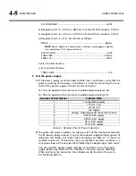
Number of Red Flashes
Problem With
1 +
unregulated
supply
2
+15V or –15V
3
+5V or –5V
4 +5V
Digital
5
Analog
Digital ground connection broken
6
DSP A +3.3V supply
7
DSP B +3.3V supply
8 CPU
+3.3V
supply
9 CPU
+2.5V
supply
Table 4-1: Decoder Chart for Power Supervisor
B)
The green LED power indicator on the lower left of the front panel monitors
the DC power supply outputs. If one or more power supply voltages are out of
tolerance, red flashes will report them according to Table 4-1. If there are
multiple values out of tolerance, they are reported one after another in a
continuous loop, with one green flash indicating the beginning of each count.
You can monitor power supply voltages at connector J7 on the power
supply board (see Section 6 for schematic and parts locator drawing).
When one faces the connector, the voltages can be found on the pins in
the following pattern:
Summary of Contents for Optimod-AM 9400
Page 1: ...Operating Manual OPTIMOD AM 9400 Digital Audio Processor Version 1 2 Software...
Page 7: ...Operating Manual OPTIMOD AM 9400 Digital Audio Processor Version 1 2 Software...
Page 52: ......
Page 204: ......
Page 232: ......
Page 260: ......
Page 261: ...OPTIMOD AM DIGITAL TECHNICAL DATA 6 29...
Page 267: ...OPTIMOD AM DIGITAL TECHNICAL DATA 6 35 CPU Module...
Page 273: ...OPTIMOD AM DIGITAL TECHNICAL DATA 6 41 RS232 BOARD PARTS LOCATOR...
Page 275: ...OPTIMOD AM DIGITAL TECHNICAL DATA 6 43 8300 POWER SUPPLY PARTS LOCATOR...
Page 284: ...6 52 TECHNICAL DATA ORBAN MODEL 9400 DSP BOARD PARTS LOCATOR DRAWING 32170 000 14...
Page 292: ...6 60 TECHNICAL DATA ORBAN MODEL 9400 DISPLAY BOARD PARTS LOCATOR...
Page 293: ...OPTIMOD AM DIGITAL TECHNICAL DATA 6 61 DISPLAY BOARD...