Installation
Section 2-3
51
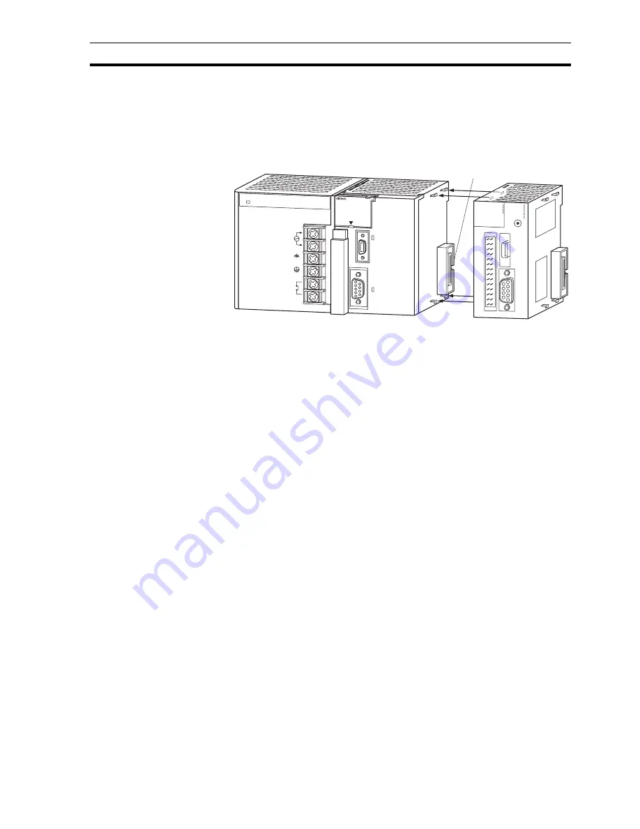
To connect the CJ1W-MCH72 to the PLC, perform the following steps:
1 Align the connectors of the units.
CJ1W-MCH72 hardware installation
2 Move the yellow sliders at the top and bottom of the unit to the front.
3 Attach the CJ1W-MCH72 to the PLC.
4 Push the yellow sliders at the top and bottom of the unit to the rear to lock
them.
2-3-2
Setup
After the installation of the unit in a PLC system, the following initial setup
procedure must be executed:
• A unique unit number must be set. Refer to section 2-3-2-1.
• An I/O table must be created in the PLC, to register the unit on the PLC
CPU. Refer to section 2-3-2-2.
This initial setup procedure makes sure that the unit can start up properly and
can be configured for operation.
2-3-2-1 Setting the unit number
To set the unit number, perform the following steps:
1 Turn off the power supply to the PLC system.
2 Use a small screwdriver to set the unit number selector switch to the new
unit number.
Note
The maximum current consumption of the CJ1W-MCH72 is 680 mA. Make sure that the
total current consumption of all units connected to the same CPU backplane or expan-
sion backplane is not greater than the output capacity of the Power Supply Unit.
PA205R
POWER
IN PUT
AC100-240V
L2/N
L1
DC24V
AC240V
OUTPUT
R UN
PER IPHER AL
ER R /ALM
R UN
IN H
COMM
PR PHL
CONTR OLLER
CJ1G-C PU44
SYSMAC
PR OG R AMMABLE
PORT
OPEN
BUSY
MCPWR
Connector
BF
NO.
UNIT
ER H
0
12
345678
9A
BCD
EF
ER C
R UN
0
1
2
3
4
5
6
7
MCH72
WDOG
Note
If the sliders are not properly locked, it is possible that the unit does not operate cor-
rectly.
Note
Communication errors can occur in the Encoder Interface when Contact Output Units
are installed close to the CJ1W-MCH72. This is caused by noise generated by the Con-
tact Outputs.
If Contact Output Units and a CJ1W-MCH72 are installed on the same rack and com-
munication errors occur, do one of the following:
•
Install the Contact Output Units at maximum distance from the CJ1W-MCH72.
•
Use surge absorbers for the Contact Outputs.
Summary of Contents for SYSMAC CJ Series
Page 2: ......
Page 70: ...Specifications Section 2 4 58...
Page 84: ...FINS commands Section 3 4 72...
Page 148: ...All BASIC commands Section 4 2 136 AXIS 1 AXIS 0...
Page 370: ...Section 358...


