3-33
9. Press the SERVO (DATA) Key to turn on the servo. (This step is not required if the Run Command
Input is ON.)
10. Perform auto-tuning, using the Up Key for forward operation and the Down Key for reverse opera-
tion. Continue pressing the key until “End” is displayed, indicating that auto-tuning has been com-
pleted.
11. Release the key. The data display will return.
12. Press the DATA Key to return to the settings mode.
D
Selecting Mechanical Rigidity
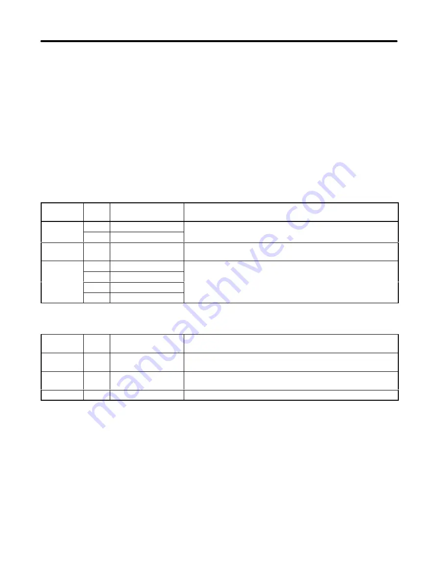
Select the set value to match the rigidity of the mechanical system.
HA/LA/V/W Models
Response
Set
value
Position loop gain
(1/s)
Representative applications
Low
001
16
Articulated robots, harmonic drives, chain drives, belt drives,
k
d i i
d i
002
28
,
,
,
,
rack and pinion drives, etc.
Medium
003
40
XY tables, Cartesian-coordinate robots, general-purpose ma-
chinery, etc.
High
004
56
Ball screws (direct coupling), feeders, etc.
g
005
78
(
g),
,
006
108
007
130
H/L Models
Response
Set
value
Position loop gain
(1/s)
Representative applications
Low
001
20
Articulated robots, harmonic drives, chain drives, belt drives,
rack and pinion drives, etc.
Medium
002
40
XY tables, Cartesian-coordinate robots, general-purpose ma-
chinery, etc.
High
003
60
Ball screws (direct coupling), feeders, etc.
Note The higher the rigidity of the mechanical system is, the higher the response becomes.
D
Auto-tuning
•
Auto-tuning will not be complete until at least three operations have been completed. Be sure there is
plenty of room for the machine to operate.
•
If the auto-tuning is not complete after three operation, operations will be repeat as long as the key is
held down.
•
The Servomotor rotation speed will be approximately 1/2 that of the jog speed (Cn-10).
•
Auto-tuning will automatically change the setting of the user parameter position loop gain (Cn-1A),
speed loop gain (Cn-04), and speed loop integration time constant (Cn-05). These values will not be
changed, however, until the auto-tuning operation has been completed.
Operation
Chapter 3


