2-2 Part Names and Functions
2-15
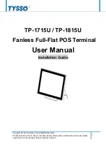
NS5 Rear Panel
Local Bus Interface Connector
Used to connect to an Expansion Interface Unit.
(Applicable with NS Ver. 6 or higher systems.) Current
Expansion Interface Units (NS-CA001, NS-CA002, and
NCCKL21) cannot be connected.
Ethernet Connector
Used to connect the Ethernet cable.
Uses a 10Base-T/100Base-T 8-pin
modular plug.
USB Slave Connector
This is a USB Type B connector.
Refer to
3-3-2 Connecting via
USB.
FG Terminal
Used to prevent malfunctions
due to noise interference.
Main Circuit DC Input Terminals
Used to connect the power supply.
Reset Switch
Used to initialize the PT. The status
of screen data, other registered data,
and the system menu, however, will
not change.
DIP Switch
Used to set the settings for
transmitting data using the
Memory Card.
Battery Cover
The battery is installed
underneath the cover.
Serial Port B Connector
Used to connect the host, CX-
Designer, and Bar Code Reader.
Uses an RS-232C 9-pin connector.
Serial Port A Connector
Used to connect the host, CX-
Designer, and Bar Code Reader.
Uses an RS-232C 9-pin connector.
USB Slave Connector
This is a USB Type B connector.
Refer to
3-3-2 Connecting via USB
.
The NS5-SQ1
@@
-V2, NS5-TQ1
@@
-V2,
and NS5-MQ1
@@
-V2 can be connected
to a PictBridge-compatible printer.
(Refer to
3-5-2 Connecting a PictBridge-
compatible Printer
.)
Precautions
for Safe Use
Confirm system safety before turning the power ON/OFF or restarting. Other-
wise the system may operate unpredictably.
Summary of Contents for NS - REV 12
Page 2: ......
Page 22: ...20 ...
Page 34: ...1 4 Procedure for Running NS series PTs 1 12 ...
Page 54: ...2 2 Part Names and Functions 2 20 ...
Page 116: ...3 11 RS 232C RS 422A Selector DIP Switch 3 62 ...
Page 144: ...4 4 Recommended Connector Cables 4 28 ...
Page 174: ...5 3 Connecting to Host via EtherNet IP 5 30 ...
Page 246: ...6 11 Verifying Tags 6 72 ...
Page 279: ...Appendix 2 Dimensions A 19 NS5 V1 V2 Cable Connection Dimensions ...
Page 332: ......
Page 333: ......