143
Functions Compatible with Servo Drivers with Absolute Encoders
Section 7-8
7-8-3
Data Format of Absolute Encoder Output
The format of data from a servo driver with an absolute encoder compatible
with the unit (model CS1W-HCA12-V1) is as follows:
Serial Data Specification
Data Format
Note
1.
“P" of ASCII code. It is 50 Hex in hexadecimal.
2.
The range of No. of rotations that can be received by the unit is between
+65535 to
-
65535.
3.
For details of the data on the number of multi-turns received from a servo
driver, please check the manual of the servo driver in use.
4.
Please set the unit function setting "high-speed counter 1 operating mode
(DM 6605)" to either ABS linear (CW
-
) or ABS linear (CW+) mode corre-
sponding to the setting of reverse rotation mode on the servo driver in use.
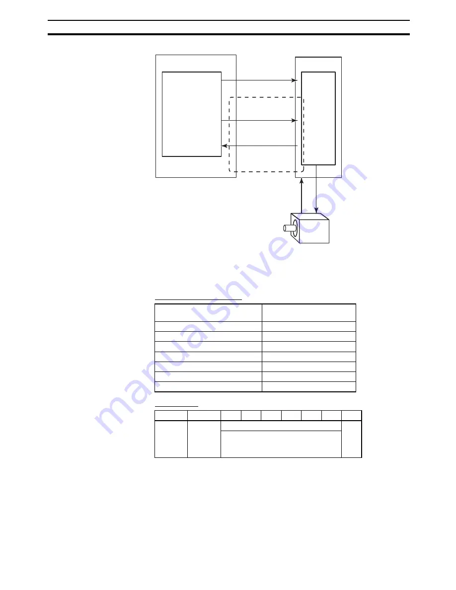
Customizable Counter Unit
Servo driver
Speed
control
Position control,
(SPED, ACC,
PULS or PLS2
instruction)
SEN signal
Absolute encoder data
Power cable
(U, V, W)
Absolute encoder signal
(line driver)
Servo motor
with Absolute encoder
Analog output
(Speed control)
−
10 to 10 V, etc.
The number of digits for data on
the number of rotations
5 digits
Data transmitting method
Asynchronous
Transfer rate
9600 bits/s
Start bit
1 bit
Stop bit
1 bit
Parity
Even numbers
Character code
ASCII 7 bits
Data format
8 characters
Byte
+0
+1
+2
+3
+4
+5
+6
+7
P (See
note 1.)
Data on the number of rotations
CR
Sign (+ or
-
)
Whole numbers (5 digits of decimal
numbers)
Summary of Contents for CS1W-HCA12-V1
Page 2: ......
Page 6: ...vi...
Page 20: ...xx Conformance to EC Directives 7...
Page 38: ...18 Models and System Configurations Section 1 2...
Page 78: ...58 Fail safe Circuits Section 3 5...
Page 138: ...118 AR Area Section 6 4...
Page 204: ...184 Improved Instructions Section 7 14...
Page 222: ...202 Cycle Time Section 8 3...
Page 240: ...220 Troubleshooting Flowcharts Section 9 5...
Page 244: ...224 Precautions when Using the CX Programmer Appendix A...
Page 252: ......
Page 253: ......


