1-14
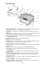
1.9 Front view
1. Liquid crystal display (LCD) — The display (2-line
×
20-character) which shows the machine’s
status and lets you see what you’re entering during various operations
2. Control Panel — The keys you use to operate your fax machine. (See pages 1.6–1.7 for more
details.)
3. Paper cassette — One of two locations where you put the recording paper (the Multipurpose tray
is the other). Holds up to 400 sheets, either A4, B4, A5R or B5R-sized paper.
4. Recording paper level indicator — Shows the level of the current paper supply without requiring
you to open the paper cassette.
5. Original document exit — Where the original document comes out.
6. Side cover — Open to fixing printout jams.
7. Multipurpose tray — One of two locations where you put the recording paper (the paper cassette
is the other). Holds only one sheet, either A4, A5, A5R or B5 size paper.
8. Top cover release — Pull up on this to open the top cover.
9. Top cover — Opens to provide access for changing the toner and drum cartridge (or occasionally,
fixing printout jams).
10. Book cover — Opens to scan an original document using the flatbed scanner (fbs).
11. Document tray — Supports the original document for straighter feeding into the automatic
document feeder (adf).
12. Document guides — You can adjust these for the width of the original document so it will feed
properly into the adf.
13. Automatic document feeder (ADF) — The slot into which you place your original document for
faxing or copying. It holds up to 50 sheets of A4-sized paper, 25 pages of B4-sized paper or 15
pages of A3-sized paper.
14. Scanner cover — Opens to provide access, during occasional jams, to an original document you
have put into the adf.
15. Scanner cover release — Pull up on this to open the scanner cover.
16. Flatbed scanner (FBS) — Makes it possible for you to fax or copy objects and even irregularly
shaped sheets, just as on a conventional copier.
Summary of Contents for OKIOFFICE 120
Page 7: ...vi ...
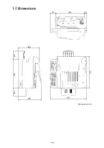
Page 17: ...1 10 1 7 Dimensions Dimension in mm ...
Page 23: ...1 16 1 11 ID Label Specification 1 12 Labels location ...
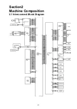
Page 24: ...2 1 Section2 Machine Composition 2 1 Interconnect Block Diagram ...
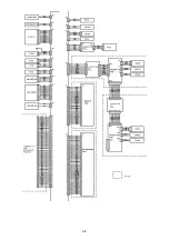
Page 25: ...2 2 ...
Page 87: ...3 46 Unique Switch F 7 and F 9 Factory use only ...


