background image

1-7

1.4.3 Fax Receiving

Item Specifications / Comments
Receive mode Fax ready, Tel/Fax Ready, Fax/Tel Ready, Ans/Fax Ready or

Tel ready mode; user selectable.

Distinctive ring detection Ability to answer on specific ring patterns. User selectable
Number of rings In Fax ready mode, select 1 to 9 rings.
Automatic reduction Automatically reduces incoming documents to fit on receive paper.
Receive reduction rate
(Auto)

Auto: 50 % to 100 % when auto reduction is selected.
Reduction margin: 0-85 mm (Initial value: 24 mm)

Receive reduction rate
(Fixed value)

100, 97, 91, 81, 75 % :User selectable

Half-page reception Available.

(This feature tells the machine to combine two of half-page
receptions onto a single sheet.)

SecureMail 10 mailboxes for receiving, 4 digits ID-code.

Holds a SecureMail up to 31 days.

SecureMail
(ITU-T subaddress /
password)

Using the ITU-T sub-address and password provide to SecureMail
communication not only with other OKIOFFICE 120 fax machines (or
compatible brand), but fax machines of other manufactures as well.
Up to 50 mailboxes for receiving, 4 digits passcode.
Holds a document up to 31 days (or no limit).

Block junk fax Ability to reject “junk fax” receptions: user selectable three options.
Closed network Proprietary network option
Out-of paper reception Receives up to 100 communications to memory if recording paper

supply or printer supplies are empty.

Security reception You can tell the machine to keep all received faxes in memory (but

not print them) after a certain time; then, later, you instruct it to go
ahead and print out the saved faxes.

Remote reception upon
second phone connection

Fax is activated upon termination of a call that is answered by a
telephone connected to second phone jack.

1.4.4 Polling

Item Specifications / Comments
Delayed polling Programmable up to 31 days in advance.
Regular polling Retrieves a document from the remote fax machine.
Continuous polling Retrieves continuously a document from any remote fax machine for

the designed time.

Database polling Possible only in communication with certain memory equipped

OKI fax machine.
Retrieves a document stored as a file in the remote fax machine’s
memory.
You can enter as many as 10 file numbers in one operation.
Enter 4 digits file number.

Database polling
(ITU-T subaddress
/password)

Using the ITU-T sub-address and password provide to database
polling communication not only with other OKIOFFICE 120 fax machines 
(or compatible brand), but fax machines of other manufactures as well.
Retrieves a document stored in a memory-box in the remote fax
machine.
You must enter a ITU-T subaddress to retrieves a document from
any remote fax’s memory box.

Summary of Contents for OKIOFFICE 120

Page 1: ...U K version 1 0 15 April 1998 All specifications are subject to change without notice OKIOFFICE 120 Facsimile System Maintenance Manual ...

Page 2: ...6 1 12 Labels location 1 16 Section2 Machine Composition 2 1 2 1 Interconnect Block Diagram 2 1 2 2 Main Control PCB 2 3 2 3 NCU PCB 2 5 2 4 Power Supply Unit PSU 2 6 2 5 Sensors 2 7 2 5 1 Sensor Locations 2 7 2 5 2 Sensor Descriptions 2 7 2 6 Document Scanning Sequence 2 9 2 6 1 Document Detection 2 9 2 6 2 Document Separation 2 9 2 6 3 Document Transport 2 9 2 6 4 Document Scanning 2 9 2 6 5 Doc...

Page 3: ...3 16 Memory Switch A 5 Dialer 3 17 Memory Switch B 0 Transmission 3 17 Memory Switch B 1 Transmission 3 18 Memory Switch B 2 Transmission 3 19 Memory Switch B 3 Transmission 3 19 Memory Switch B 5 Transmission 3 20 Memory Switch C 0 Reception 3 20 Memory Switch C 1 Reception 3 21 Memory Switch D 0 Reception 3 22 Memory Switch D 1 Reception 3 22 Memory Switch D 2 Reception 3 23 Memory Switch D 3 Re...

Page 4: ...1 3 10 2 Printer Test 3 53 3 10 3 Stamp Test 3 53 3 10 4 Feeder test 3 54 3 10 5 Set Background Level 3 54 3 11 Print Machine Parameters Memory Switch and Unique Switch Settings 3 55 3 12 Factory Functions 3 55 3 12 1 Function List 3 55 3 12 2 LED Test 3 56 3 12 3 LCD Test 3 56 3 12 4 Key Panel Test 3 56 3 12 5 SRAM Check 3 57 3 12 6 DRAM Check 3 58 3 12 7 RTC real time clock Test 3 58 3 13 Line T...

Page 5: ... Service 4 20 4 16 LCD Failure 4 23 4 17 General Power Failure 4 23 4 18 Cleaning the Unit 4 24 Cleaning the Document Feeder Area 4 24 Cleaning the Inside of Contact Glass 4 24 Cleaning the FBS 4 25 Cleaning the LED print head 4 25 Section5 Disassemble 5 1 5 1 Rear cover 5 3 5 2 Shielding plate R 5 3 5 3 Front cover 5 4 5 4 Upper right cover 5 4 5 5 Book cover 5 5 5 6 Upper rear cover 5 5 5 7 Uppe...

Page 6: ... 34 5 47 Pickup roller 5 35 5 48 ADF motor and FBS motor 5 36 5 49 Inverter PCB 5 39 5 50 Mirror carriage A and B 5 40 5 51 Lamp 5 44 5 52 Mirror A and B 5 45 5 53 Control panel PCB 1 and 2 5 46 5 53 LCD assembly 5 47 5 54 Connect B PCB 5 47 5 55 Speaker 5 48 5 56 Rear cover B 5 48 5 57 PES sensor 5 49 5 58 PES sensor optional paper supply unit 5 50 5 59 Solenoid of optional paper supply unit 5 51...

Page 7: ...vi ...

Page 8: ...eneral Description 1 1 Product Description The OKIOFFICE 120 is a Multi function product with flat bed scanner and Group 3 facsimile machine Documents are printed on plain paper using dry electrophotographic printing ...

Page 9: ...9 V 27ter and V21 Control signal speed is 300 bps ITU T sub address password Supported Triple Access Allows up to three simultaneous operations Display LCD 2 lines 20 characters per line Scanning method Flatbed CCD Recording method Dry electrophotographic LED process Scanning width 208 mm 252 mm 294 mm Recording width 206 mm 251 mm Acceptable document size ADF Auto Document Feeder section Single s...

Page 10: ... 3 104 7g m2 FBS Flatbed scanner section Max 257 mm W 364 mm L Min No limit Document size auto detection ADF section A4 B4 A3 FBS section N A Scanning resolution Fax Horizontal Vertical Normal 8 dots 3 85 lines mm 203 dpi 98 dpi Fine 8 dots 7 7 lines mm 203 dpi 196 dpi Super fine 8 dots 15 4 line mm 203 dpi 392 dpi Grayscale 8 dots 7 7 line mm 203 dpi 196 dpi If the remote unit has 400 400 dpi pri...

Page 11: ... 182 mm L A4 210 mm W 297 mm L A5R 210 mm W 146 mm L Paper cassette capacity Paper cassette 400 sheets 200 sheets option 200 sheets option Multipurpose tray 1 sheet Toner yield Approx 6000 pages Based on A4 sized sheets 5 document coverage and continuous printing Drum yield Approx 10000 pages Printer warm up time Under 40 second 1 3 4 Memory specifications Item Specifications Comments Document mem...

Page 12: ...2400 2400 Carrier frequency Hz 1800 Detection method Synchronism Automatic equalizer Automatic adaptive equalizer Transmission mode V 29 V 27ter V 21 Modulation method 16 Pt QAM 8 Pt QAM 8 Pt PhM 4 Pt PhM FSK Transmission speed bit s 9600 7200 4800 2400 300 Modulation speed baud 2400 2400 1600 1200 300 Carrier frequency Hz 1700 1800 f 0 1850 f 1 1650 Detection method Synchronism FS Automatic equal...

Page 13: ...eceive 10 mailboxes for receiving 4 digits ID code SecureMail ITU T subaddress password Transmit and receive 50 mailboxes for receiving 4 digits passcode Group communication Allows multiple broadcast or polling locations to be placed in up to 32 call groups Up to 200 locations can be placed in a group Group 0 includes all autodialer locations Security transmission Compares the last 4 numbers of th...

Page 14: ...tary network option Out of paper reception Receives up to 100 communications to memory if recording paper supply or printer supplies are empty Security reception You can tell the machine to keep all received faxes in memory but not print them after a certain time then later you instruct it to go ahead and print out the saved faxes Remote reception upon second phone connection Fax is activated upon...

Page 15: ... SecureMail box list SecureMail boxes with owners names SecureMail reception message Notifies mailbox owners of SecureMail receptions Confirmation report Transmit Confirmation Report TCR or Receive Confirmation Report RCR User selectable on off Activity journal Prints a cumulative total of the last about 125 transmissions and or receptions user selectable as manual or automatic Cover page Transmit...

Page 16: ...nd continuos printing Transfer roller 30000 pages Fuser unit 60000 pages Stamp 30000 times 1 6 Option Item Specifications Comments Paper supply unit A4 A5 A5R B5 200 sheets capacity Handset Mark IV Upgrade Memory Plus 2 MB Plus 4MB or Plus 8MB RS 232C interface Kit Class 1 Second phone line kit AL 100 Printer Controller Kit WP 100 Scramble Kit DS 100 ...

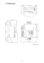
Page 17: ...1 10 1 7 Dimensions Dimension in mm ...

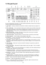
Page 18: ...curred during fax communication or your fax machine encounters a problem printing a fax or copy Check the display or an error report for more information 8 PAPER JAM light Glows when a printout received fax message or copy becomes jammed in your fax machine 9 REPLACE PAPER light Glows when the paper cassette is empty See page 1 16 for more details on replacing paper 10 GROUP DIAL Helps you set up ...

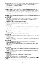
Page 19: ...h command levels 23 In Fax mode DIALLING OPTIONS Press this to insert special symbols into telephone numbers see page 2 7 Or in Copy mode SORT COPY Press this key to toggle the sorting of printed copies 24 In Fax mode PROGRAM Scrolls moves through features and command options as displayed on the LCD Or in Copy mode Press to increase the reduction or enlargement rate at 1 intervals 25 In Fax mode F...

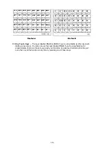
Page 20: ...tab B offer one touch dialling convenience You also can use the keys labelled 73 80 if you re using fliptab B for programmable functions this lets you teach your machine an advanced multi step function just once then recall the function at any time by pressing one of these keys ...

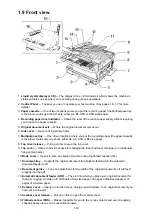
Page 21: ...B5 size paper 8 Top cover release Pull up on this to open the top cover 9 Top cover Opens to provide access for changing the toner and drum cartridge or occasionally fixing printout jams 10 Book cover Opens to scan an original document using the flatbed scanner fbs 11 Document tray Supports the original document for straighter feeding into the automatic document feeder adf 12 Document guides You c...

Page 22: ...ur machine this is where you plug in the cord 19 PHONE1 jack Where you plug in the optional handset 20 AC power socket jack Where you plug in the AC power cord 21 AC power switch Turns your fax machine on and off 22 Paper tray Holds up the printout fax or copy after it emerges 23 Printed document exit Where the printout fax or copy emerges 24 Handset optional Used for voice communication ...

Page 23: ...1 16 1 11 ID Label Specification 1 12 Labels location ...

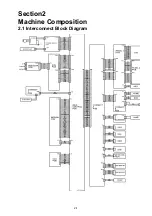
Page 24: ...2 1 Section2 Machine Composition 2 1 Interconnect Block Diagram ...

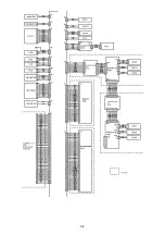
Page 25: ...2 2 ...

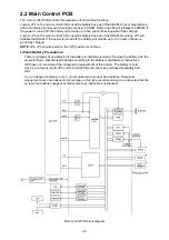
Page 26: ...ck up when fully charged NOTE JP4 JP5 should remain in the ON position at all times Lithium Battery Precautions There is a danger of an explosion if the battery is installed incorrectly Replace the battery with the equivalent type Discard used batteries according to the battery manufacturer s instructions OKI does not recommend the independent replacement of this battery The battery is sold only a...

Page 27: ...CCD such as magnification reduction and halftone Modem The modem facilitates modulation and demodulation of data for far communication Memory FLASH MEMORY SRAM DRAM FLASH MEMORY The FLASH MEMORY contains all program instructions for unit operation SRAM The SRAM which is backed up by a lithium battery is used to store user programmed information DRAM The DRAM is used for buffer which is backed up b...

Page 28: ...or components of the NCU CML relay Connects the telephone line to the phone or fax S relay Used to send dial pulse signals in pulse dialling H relay Connects the tel1 and tel2 line to the fax machine Off Hook detector Detects the Off hook condition of the handset Voltage circuit Supplies 24 volt to the H relay for on hook off hook detection for the fax unit Ring signal detector Used to detect the ...

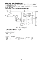
Page 29: ...ding to instructions received from the heater control circuit If an over current is sensed in the secondary circuit power is interrupted Power supply unit block diagram The power supply unit has two output connectors The following table shows the connector outputs CN2 to the Fuser Heater Pin No 1 2 Output L N P1 to the Main Control PCB Pin No 1 2 3 4 5 6 7 8 9 10 11 12 13 Output voltage 24V GND HC...

Page 30: ...ion H Micro switch DS1 Document Sensor 1 Presence of document in feeder Detection L Not detection H Photo interrupter DA3 Document Sensor A3 Document size A3 Detection L Not detection H Photo interrupter HOME Mirror carriage home position sensor Mirror carriage position Detection H Not detection L Photo interrupter END Mirror carriage end position sensor Mirror carriage position Detection H Not de...

Page 31: ... or close Open H Close L Micro switch SCOP Second cover OPen sensor Detects second cassette s side cover open or close Open H Close L Micro switch Code Name Detects logic Sensor Type ADF Inter lock Interlock Switch ADF Scanner cover open or close Open H Close L Micro switch COVER SW Cover switch Detects top cover open or close Open DC24V OFF Close DC24V ON Micro switch Detects recording paper size...

Page 32: ...cument reaches the scan wait position The machine uses the distance from DS2 to the scan wait position and the diameter of the feed roller to determine the number of rotations necessary to feed the document to the scan wait position 2 6 4 Document Scanning When the document reaches the scan wait position the machine waits for the next command It will start scanning the document when either the sta...

Page 33: ...urned off The scanner continues to remain active for a few more seconds in case there is another document to follow Document scanning in ADF section Document scanning in FBS section 2 6 5 Document Discharge The scanned document is discharged through the document exit by the exit roller ...

Page 34: ...s then fed by the rotation of the platen roller 2 8 Image Processing Incoming data is received from the telephone line by the NCU and sent to the main control PCB The modem located on the main control PCB demodulates the data The data is then sent to the printer for image processing The image processing is roughly divide into the following steps 1 Drum Charging 2 Drum Exposure 3 Development 4 Imag...

Page 35: ...ide the printer cover closes down over the drum and projects light onto the drum surface When the document is to be printed individual elements in the LED print head turn on and expose the drum where ever a dark area should appear in the document 2 8 3 Development Toner is applied to the invisible static image on the Drum and a toner image is created on the surface Part Name Function 1 Toner Agita...

Page 36: ...ecause the paper is always pressed by the Drum and the Image Transfer Roller 2 8 5 Residual toner distribute The residual toner must be removed from the drum This step does not actually remove the residual toner from the drum surface Instead a Eraser brush is used to evenly distribute the remaining toner over the drum surface When the drum surface is charged in preparation for printing the next do...

Page 37: ...tects a high temperature malfunction Fusing Temperature Control Circuit The Thermistor detects the surface temperature of the Heater Roller and inputs that analog voltage into the Main Control PCB Corresponding to this data the Heater Lamp ON OFF signal is output to the Heater ON OFF switch of the power supply unit causing the Heater Lamp to turn ON or OFF to control the fusing temperature When th...

Page 38: ...perature of the Heater Roller reaches approx 185 C 2 Printing When the printer obtains the printing command from its controller the Heater Roller is maintained at 185 C After printing the printer turns to standby mode The fuser kept at low temperature 3 Standby mode The Heater Roller maintained at approx 100 C 4 Sleep mode In this mode saving the power ...

Page 39: ...mber Dial tone Dial number Calling CNG Answer Connect the line CED 2100Hz Training Fax Message Training Fax Message CNG 1100Hz NSF CSI DIS NSS TSI DCS Training TCF CFR or FTT MPS MCF EOP DCN MCF Disconnect the line Disconnect the line FTT if training fails CFR if training succeeds Next page If multi page transmission ...

Page 40: ...ed Station Set Document Set Dial Number Dial tone Dial number Calling CNG Answer Connect the line CED 2100Hz Training Fax Message Training Fax Message CNG 1100Hz NSF CSI DIS NSS CIG DTC Training TCF CFR MPS MCF EOP DCN MCF Disconnect the line Next page If multi page transmission NSS TSI DCS ...

Page 41: ...er Dial tone Dial number Calling CNG Answer Connect the line CED 2100Hz Training Fax Message Training Fax Message CNG 1100Hz NSF CSI DIS Training TCF CFR PPS EOP PPR PPS EOP Training Fax Message MCF Disconnect the line Disconnect the line Next block ERROR NSS TSI DCS Retransmission NO ERROR PPS EOP MCF DCN NO ERROR ...

Page 42: ...nance mode PROGRAM 6 Access the printer maintenance mode Print Program Mode List PROGRAM 8 Prints a list of the unit s programming modes Test Modes PROGRAM 9 Allows the technician to perform a series of diagnostic tests Print Machine Parameters Memory Switches and Unique Switches List PROGRAM A Prints a list of the machine switch settings showing the default settings and current settings Factory F...

Page 43: ...ate through the machine parameter settings Press key to move the cursor to the left Press to move the cursor to the right Press the 0 or 1 on the numeric keypad to change the bit value Press ENTER to save the setting of the displayed parameter and advance to the next parameter Continue pressing ENTER until the desired parameter is shown in the display Be sure to press ENTER after each parameter is...

Page 44: ... 12 db 6 1 0 1 0 1 5 0 Non loaded cable compensation RX 0 0 1 1 0 db 4 db 8 db 12 db 4 1 0 1 0 1 3 Output attenuation See table below 2 Note The setting of this switch is available only 1 when setting other than 0 dB and this setting is 0 used instead of Memory Switch B 1 bit 3 0 Machine Parameter A 1 Output attenuation Switch 15 dB 14 dB 13 dB 12 dB 11 dB 10 dB 9 dB 8 dB 7 dB 6 dB 5 dB 4 dB 3 dB ...

Page 45: ...evel See table below 1 1 attenuation 0 1 Machine Parameter A 2 DTMF output level attenuation Factory default is 8 dB Switch 3 Switch 2 Switch 1 Switch 0 Attenuation 0 0 0 0 0 dB 0 0 0 1 1 dB 0 0 1 0 2 dB 0 0 1 1 3 dB 0 1 0 0 4 dB 0 1 0 1 5 dB 0 1 1 0 6 dB 0 1 1 1 7 dB 1 0 0 0 8 dB 1 0 0 1 9 dB 1 0 1 0 10 dB 1 0 1 1 11 dB 1 1 0 0 12 dB 1 1 0 1 13 dB 1 1 1 0 14 dB 1 1 1 1 15 dB ...

Page 46: ... changes by 0 65mm 00110100 33 77 mm 00110101 34 42 mm 00110110 35 06 mm 00110111 35 71 mm 4 1 Note These values 00111000 36 36 mm 00111001 37 01 mm 00111010 37 66 mm 00111011 38 31 mm 3 1 are factory set and should not be adjusted unless instructed by a OKI technical representative 00111100 38 96 mm 00111101 39 61 mm 00111110 40 26 mm Initial setting 00111111 40 91 mm 2 1 01000000 41 56 mm 010000...

Page 47: ...0011 22 73 mm 00100100 23 38 mm 00100101 24 03 mm 00100110 24 68 mm 4 0 Note These values 00100111 25 32 mm 00101000 25 97 mm 00101001 26 62 mm 00101010 27 27 mm 3 1 are factory set and should not be adjusted unless instructed by a OKI technical representative 00101011 27 92 mm Initial setting 00101100 28 57 mm 00101101 29 22 mm 00101110 29 87 mm 2 0 00101111 30 52 mm 00110000 31 17 mm 00110001 31...

Page 48: ...0000011 the DRAM capacity is 2MB 2 0 If this switch shows 00001111 it means the machine has 4MB DRAM capacity 1 0 Similarly 00111111 means 6MB capacity 0 0 Machine Parameter A 8 Switch Initial Setting Adjust Usage Comments 7 0 This switch indicates the DRAM capacity 6 0 This switch is read only do not set any character 5 0 DRAM capacity indication 4 0 This switch can indicate If the machine has 10...

Page 49: ... 0 Each setting changes by 0 65mm 00000111 4 55 mm 00001000 5 19 mm 00001001 5 84 mm 00001010 6 49 mm 4 0 Note These values 00001011 7 14 mm 00001100 7 79 mm 00001101 8 44 mm 00001110 9 09 mm 3 1 are factory set and should not be adjusted unless instructed by a OKI technical representative 00001111 9 74 mm Initial setting 00010000 10 39 mm 00010001 11 04 mm 00010010 11 69 mm 2 1 00010011 12 34 mm ...

Page 50: ...ch setting changes 00010010 11 69 mm 00010011 12 34 mm 00010100 12 99 mm 00010101 13 64 mm 4 1 by 0 65mm Note These values 00010110 14 29 mm 00010111 14 94 mm 00011000 15 58 mm 00011001 16 23 mm 3 1 are factory set and should not be adjusted unless instructed by a OKI technical representative 00011010 16 88 mm Initial setting 00011011 17 53 mm 00011100 18 18 mm 00011101 18 83 mm 2 0 00011110 19 48...

Page 51: ...ing 10001000 0 5 mm 2 0 10010000 1 0 mm 1 0 10011000 1 5 mm 10100000 2 0 mm 0 0 11100100 6 2 mm Minimum Machine Parameter B 3 Switch Initial Setting Adjust Usage Comments 7 0 FBS scanner registration adjustment Horizontal Switch 76543210 Settings 01111111 7 9 mm Maximum 6 0 Adjusts the start point to scan the document The plus setting increase the 00100000 2 0 mm 5 0 left margin and the minus sett...

Page 52: ...0 5 mm 10000010 1 0 mm 2 0 Each setting changes by 0 5 mm 10000011 1 5 mm 10000100 2 0 mm 1 0 10000101 2 5 mm 10000110 3 0 mm 0 0 10000111 3 5 mm 10001000 4 0 mm 10001001 4 5 mm 10001010 5 0 mm Machine Parameter B 5 Switch Initial Setting Adjust Usage Comments 7 0 Printer registration adjustment Horizontal Switch 76543210 Settings 00010100 20 mm 6 0 at the first cassette 00010011 19 mm 5 0 Adjusts...

Page 53: ...tting 10000001 1 mm 2 0 Each setting changes by 1 mm 10000010 2 mm 10000011 3 mm 1 0 0 0 10010100 20 mm Machine Parameter B 7 Switch Initial Setting Adjust Usage Comments 7 0 Printer registration adjustment Horizontal Switch 76543210 Settings 00010100 20 mm 6 0 at the optional third cassette 00010011 19 mm 5 0 Adjusts the start point to print 00000011 3 mm 4 0 The plus setting increase the left ma...

Page 54: ...11 3 mm 1 0 0 1 10010100 20 mm Machine Parameter B 9 J 4 Factory use only Machine Parameter J 5 Switch Initial Setting Adjust Usage Comments 7 1 Slice level adjustment in Switch 76543210 6 0 Normal resolution 10001010 Darkest setting 5 0 4 0 10000001 3 1 10001000 Default setting 2 0 00000001 1 0 0 0 00001100 Lightest setting Note Do not exceed each maximum settings Machine Parameter J 6 Switch Ini...

Page 55: ... Default setting 2 0 00000001 1 0 0 0 00001010 Lightest setting Note Do not exceed each maximum settings Machine Parameter J 8 Switch Initial Setting Adjust Usage Comments 7 0 Slice level adjustment in Switch 76543210 6 0 grayscale resolution 11111111 Darkest setting 5 0 4 0 10000001 3 0 00000000 Default setting 2 0 00000001 1 0 0 0 01111111 Lightest setting Note Do not exceed each maximum setting...

Page 56: ... through the memory switch settings Press key to move the cursor to the left Press to move the cursor to the right Press the 0 or 1 on the numeric keypad to change the bit value Press ENTER to save the setting of the displayed memory switch and advance to the next memory switch Continue pressing ENTER until the desired memory switch is shown in the display Be sure to press ENTER after each memory ...

Page 57: ...o PSTN the unit checks for dial tone and acts according to the setting of memory switch A 0 bit 1 When set to PBX the unit always dials a given number of seconds after going off hook Memory switch A 1 sets the number of seconds Memory Switch A 1 Dialer Switch Initial Setting Adjust Usage Comments 7 0 Factory use only 6 0 Factory use only 5 0 Factory use only 4 0 Factory use only 3 0 PBX mode dial ...

Page 58: ...Set at 0 2 times 2 times 2 times 2 times 2 times Set at 1 4 times 1 times 1 times 1 times 1 times 5 0 Overseas mode 0 No 1 Yes Re enables echo suppression that is disabled by the CED signal 2100 Hz Also ignores the first DIS signal and transmits the DCS signal in response to the second DIS signal 4 0 V 29 Echo Protect tone 0 No 1 Yes International telephone lines equipped with echo suppression wil...

Page 59: ...rval between DCS and TCF When FTT is received after DCS and TCF signals due to line echo increase the interval between DCS and TCF signals using this switch 4 0 75 ms 300 ms 450 ms 600 ms Switch 5 0 0 1 1 Switch 4 0 1 0 1 3 1 2 0 Output attenuation See table below 1 0 0 1 Memory Switch B 1 Output attenuation Switch 15 dB 14 dB 13 dB 12 dB 11 dB 10 dB 9 dB 8 dB 7 dB 6 dB 5 dB 4 dB 3 dB 2 dB 1 dB 0 ...

Page 60: ...ning TTI transmission off may violate local or federal regulations 3 0 ECM response time 0 3 sec 1 4 8 sec The time limit to receive the response signal for the ECM post message 2 0 ECM error retransmit time 0 200 ms 1 400 ms The time limit before the ECM error is retransmitted 1 0 Interval between DIS and DCS 0 0 0 ms 500 ms 1000 ms 1500 ms Switch 1 0 0 1 1 Switch 0 0 1 0 1 Memory Switch B 3 Tran...

Page 61: ...0 Action after EOR signal 0 Continue 1 Discontinue Sets action after receiving PPR four times at 2400 bps Memory Switch B 6 B 9 Factory use only Memory Switch C 0 Reception Switch Initial Setting Adjust Usage Comments 7 0 Data error rate 0 10 1 20 Determines the allowable number of erred lines out of total lines received in a document 6 0 Pause one second after sending CED 0 No 75 ms 1 Yes 1 sec A...

Page 62: ...t print the data even though the following protocol is not succeeded 2 0 Disable ITU T superfine reception 0 Yes 1 No Set to 1 if a compatibility error occurs because the transmitting machine does not understand the extended frame for ITU T superfine resolution Note Setting this switch to 1 will disable superfine mode 1 0 G3 echo receive Adjusts the delay between detection of training TCF and send...

Page 63: ...pensate the group delay 1 0 Digital cable equalizer 0 Free 1 Hold When set to 1 become efficient for the line short break but become weak for the line noise It s available only for communication at 14 400 or 12 000 bit s 0 1 Carrier detection level 0 43 48 dB 1 47 52 dB Setting this switch to 1 increases the sensitivity Memory Switch D 1 Reception Switch Initial Setting Adjust Usage Comments 7 1 E...

Page 64: ...ct Lenient 0 1 0 1 1 1 EYE Q check level at 0 0 1 1 0 0 4800 bps Strict Lenient 0 1 0 1 Memory Switch D 3 Reception Switch Initial Setting Adjust Usage Comments 7 0 Factory use only 6 0 Factory use only 5 0 Factory use only 4 0 Factory use only 3 0 Factory use only 2 0 Factory use only 1 0 Delete receive echo of CFR at the receiver side 0 No 1 Yes Modem will be opened only in high speed mode Sets ...

Page 65: ... to unlimited will override document jam sensing Memory Switch E 1 F 9 Factory use only Memory Switch G 0 Remote reception Switch Initial Setting Adjust Usage Comments 7 0 Factory use only 6 1 CML relay off time after dialing 0 1 sec 1 200 ms When dialing from the keypad phone line noise may occur as the CML relay switches on and off Set this switch to 0 to avoid this 5 0 DTMF tones heard through ...

Page 66: ...ms 5 1 0 1 1 1 70 ms 1 0 0 0 80 ms 1 0 0 1 90 ms 1 0 1 0 100 ms 1 0 1 1 110 ms 4 1 1 1 0 0 120 ms 1 1 0 1 130 ms 1 1 1 0 140 ms 1 1 1 1 150 ms 3 0 Off hook on hook detect time Sets the time interval between the on hook and off hook or off hook on hook condition Switch 3 2 1 0 Time 0 0 0 0 0 ms 0 0 0 1 100 ms 2 1 0 0 1 0 200 ms 0 0 1 1 300 ms 0 1 0 0 400 ms Default 0 1 0 1 500 ms 0 1 1 0 600 ms 1 0...

Page 67: ...0 0 400 ms 1 1 0 1 0 1 500 ms 0 1 1 0 600 ms 0 1 1 1 700 ms 1 0 0 0 800 ms 1 0 0 1 900 ms 0 1 1 0 1 0 1000 ms 1 0 1 1 1100 ms 1 1 0 0 1200 ms 1 1 0 1 1300 ms 1 1 1 0 1400 ms 1 1 1 1 1500 ms Memory Switch G 3 G 4 Factory use only Memory Switch G 5 Remote reception Switch Initial Setting Adjust Usage Comments 7 0 Factory use only 6 0 Factory use only 5 0 Factory use only 4 0 Factory use only 3 0 Fac...

Page 68: ...age if error occurs during memory transmission 0 No 1 Yes For easy identification the first page of a document stored for memory transmission will print along a check message if an error occurs during memory transmission 1 1 Print check message 0 No 1 Yes To notify the user of an error a check message can be printed if a communication error occurs 0 0 Stop printing check message for a memory trans...

Page 69: ...t s Random Access Memory RAM This information is held by a battery back up when the power is lost This function does not clear the machine parameters memory switches and unique switches Therefore this setting is useful to reset the user programmed information but leave specific parameters and switches configured for a particular telephone system etc To reset only each switch see page 3 2 3 15 and ...

Page 70: ...he life monitor and the consumable order sheet data 3 6 Setting Individual Autodialer Attributes This function allows the user to configure an individual one touch or speed dial entry with the settings shown in Memory Switches B 0 B 1 B 2 and B 3 To set the individual attributes 1 Change memory switch B 5 bit 7 to a 1 See setting 3 3 1 Setting the Memory Switches for more information on changing m...

Page 71: ...ne is placed prior to the training using G3 high speed modem training V 29 3 1 Maximum transmit speed kbps 2 4 4 8 7 2 9 6 12 14 4 16 8 19 2 21 6 24 26 4 28 8 31 2 33 6 2 1 0 0 0 0 0 0 0 0 1 1 1 1 1 1 0 0 0 0 1 1 1 1 0 0 0 0 1 1 1 0 0 0 1 1 0 0 1 1 0 0 1 1 0 0 0 1 0 1 0 1 0 1 0 1 0 1 0 1 0 1 Note It is maximum 33 6 kbps only when AL 100 optional module is attached to OKIOFFICE 120 model Standard O...

Page 72: ... 1 Yes Assigns European date format to the transmitted TTI Example 29 May 1997 4 1 TTI transmit 0 No 1 Yes When set at 0 transmission of the TTI is disabled Note Turning TTI transmission off may violate local or federal regulations 3 0 ECM response time 0 3 sec 1 4 8 sec The time limit to receive the response signal for the ECM post message 2 0 ECM error retransmit time 0 200 ms 1 400 ms The time ...

Page 73: ...through the unique switch settings Press key to move the cursor to the left Press key to move the cursor to the right Press the 0 or 1 on the numeric keypad to change the bit value Press ENTER to save the setting of the displayed unique switch and advance to the next unique switch Continue pressing ENTER until the desired unique switch is shown in the display Be sure to press ENTER after each uniq...

Page 74: ...only 2 0 Factory use only 1 0 Factory use only 0 1 Factory use only Unique Switch A 1 A 9 Factory use only Unique Switch B 0 Transmission Switch Initial Setting Adjust Usage Comments 7 0 Factory use only 6 0 Factory use only 5 0 Factory use only 4 1 Factory use only 3 0 Factory use only 2 0 Factory use only 1 1 The number of times PPR is detected during ECM transmission 1 time 2 times 3 times 4 ti...

Page 75: ...0 No 1 Yes Neglect SEP bit of DTC signal or SUB bit of DCS signal at F code polled transmission Unique Switch B 7 B 9 Factory use only Unique Switch C 0 Reception Switch Initial Setting Adjust Usage Comments 7 0 Factory use only 6 0 Factory use only 5 1 MMR storage 0 No 1 Yes Determines how documents are stored in memory for transmission 4 1 Transmit CED signal when manual remote receive 0 No 1 Ye...

Page 76: ...ial setting 0 1 1 1 7 s 1 0 0 0 8 s 1 0 0 1 9 s 1 0 1 0 10 s 1 0 1 1 11 s 4 0 1 1 0 0 12 s 1 1 0 1 13 s 1 1 1 0 14 s 1 1 1 1 15 s 3 1 TCF check time in 100 ms units If the TCF time is such that poor image quality is the result lengthen the TCF check time Switch 3 2 1 0 Time 2 0 0 0 0 0 0 ms 0 0 0 1 100 ms 0 0 1 0 200 ms 0 0 1 1 300 ms 0 1 0 0 400 ms 0 1 0 1 500 ms 1 1 0 1 1 0 600 ms 0 1 1 1 700 ms...

Page 77: ...ch Initial Setting Adjust Usage Comments 7 0 Factory use only 6 0 Factory use only 5 0 Factory use only 4 0 Factory use only 3 0 Factory use only 2 0 Factory use only 1 0 Factory use only 0 1 Hyper Fine resolution 0 No 1 Yes When set at 1 Super fine SFine resolution change into Hyper fine HFine resolution Unique Switch E 1 Factory use only Unique Switch E 2 Scanner Switch Initial Setting Adjust Us...

Page 78: ...for ADF FBS copying Sets the leading edge margin from the edge of document to the start of the scanning position Switch 3 2 1 0 Settings 0 0 0 0 0 00 mm 0 0 0 1 0 65 mm 2 0 0 0 1 0 1 30 mm 0 0 1 1 1 95 mm 0 1 0 0 2 60 mm 0 1 0 1 3 25 mm 0 1 1 0 3 90 mm 1 0 0 1 1 1 4 55 mm 1 0 0 0 5 19 mm 1 0 0 1 5 84 mm 1 0 1 0 6 49 mm 1 0 1 1 7 14 mm 0 0 1 1 0 0 7 79 mm 1 1 0 1 8 44 mm 1 1 1 0 9 09 mm 1 1 1 1 9 7...

Page 79: ...1 0 0 2 60 mm 1 1 0 1 3 25 mm 4 0 As Machine Parameter B 3 is for factory adjustment do not use for field 1 1 1 0 3 90 mm 1 1 1 1 4 55 mm 3 0 Leading edge document margin settings FBS Adjusts the leading edge margin from standby position Switch 3 2 1 0 Settings 0 1 1 1 4 55 mm 0 1 1 0 3 90 mm 0 1 0 1 3 25 mm 2 0 or the mirror carriage to the start of the scanning position Each setting changes by 0...

Page 80: ... 0 1 1 3 mm 4 0 when scanning document by FBS Each setting changes by 1 mm 0 0 0 1 0 0 4 mm 0 0 0 1 0 1 5 mm 0 0 0 1 1 0 6 mm 0 0 0 1 1 1 7 mm 0 0 1 0 0 0 8 mm 3 0 0 0 1 0 0 1 9 mm 0 0 1 0 1 0 10 mm 0 0 1 0 1 1 11 mm 0 0 1 1 0 0 12 mm 0 0 1 1 0 1 13 mm 2 0 0 0 1 1 1 0 14 mm 0 0 1 1 1 1 15 mm 0 1 0 0 0 0 16 mm 0 1 0 0 0 1 17 mm 0 1 0 0 1 0 18 mm 1 0 0 1 0 0 1 1 19 mm 0 1 0 1 0 0 20 mm 0 1 0 1 0 1 2...

Page 81: ...0 0 1 1 3 mm 4 0 when scanning document by FBS Each setting changes by 1 mm 0 0 0 1 0 0 4 mm 0 0 0 1 0 1 5 mm 0 0 0 1 1 0 6 mm 0 0 0 1 1 1 7 mm 0 0 1 0 0 0 8 mm 3 0 0 0 1 0 0 1 9 mm 0 0 1 0 1 0 10 mm 0 0 1 0 1 1 11 mm 0 0 1 1 0 0 12 mm 0 0 1 1 0 1 13 mm 2 0 0 0 1 1 1 0 14 mm 0 0 1 1 1 1 15 mm 0 1 0 0 0 0 16 mm 0 1 0 0 0 1 17 mm 0 1 0 0 1 0 18 mm 1 0 0 1 0 0 1 1 19 mm 0 1 0 1 0 0 20 mm 0 1 0 1 0 1 ...

Page 82: ... 1 3 mm 4 0 margin when scanning document by FBS Each setting changes by 1 mm 0 0 0 1 0 0 4 mm 0 0 0 1 0 1 5 mm 0 0 0 1 1 0 6 mm 0 0 0 1 1 1 7 mm 0 0 1 0 0 0 8 mm 3 0 0 0 1 0 0 1 9 mm 0 0 1 0 1 0 10 mm 0 0 1 0 1 1 11 mm 0 0 1 1 0 0 12 mm 0 0 1 1 0 1 13 mm 2 0 0 0 1 1 1 0 14 mm 0 0 1 1 1 1 15 mm 0 1 0 0 0 0 16 mm 0 1 0 0 0 1 17 mm 0 1 0 0 1 0 18 mm 1 0 0 1 0 0 1 1 19 mm 0 1 0 1 0 0 20 mm 0 1 0 1 0 ...

Page 83: ...1 1 3 mm 4 0 margin when scanning document by FBS Each setting changes by 1 mm 0 0 0 1 0 0 4 mm 0 0 0 1 0 1 5 mm 0 0 0 1 1 0 6 mm 0 0 0 1 1 1 7 mm 0 0 1 0 0 0 8 mm 3 0 0 0 1 0 0 1 9 mm 0 0 1 0 1 0 10 mm 0 0 1 0 1 1 11 mm 0 0 1 1 0 0 12 mm 0 0 1 1 0 1 13 mm 2 0 0 0 1 1 1 0 14 mm 0 0 1 1 1 1 15 mm 0 1 0 0 0 0 16 mm 0 1 0 0 0 1 17 mm 0 1 0 0 1 0 18 mm 1 0 0 1 0 0 1 1 19 mm 0 1 0 1 0 0 20 mm 0 1 0 1 0...

Page 84: ...thing in Normal Fine and SFine resolutions in receive mode 0 No 1 Yes 0 1 Smoothing in Normal Fine and SFine resolutions in copy mode 0 No 1 Yes Unique Switch F 1 Printer Switch Initial Setting Adjust Usage Comments 7 0 Factory use only 6 0 Factory use only 5 0 Factory use only 4 1 Factory use only 3 0 Factory use only 2 0 Factory use only 1 0 Factory use only 0 0 Print reduction 0 No 1 Yes If the...

Page 85: ...n Default 3 0 2 1 1 0 1 1 1 1 1 1 0 0 252 min 1 1 1 1 1 1 0 1 253 min 0 1 1 1 1 1 1 1 1 0 254 min 1 1 1 1 1 1 1 1 255 min Unique Switch F 3 Printer Switch Initial Setting Adjust Usage Comments 7 0 Factory use only 6 0 Factory use only 5 0 Factory use only 4 0 Factory use only 3 0 Factory use only 2 0 Switch 2 1 0 0 0 0 Lightest 0 0 1 Light 1 0 Printing density 0 1 0 Not as light 0 1 1 Normal Defau...

Page 86: ...e received document upon receiving the data into fax s memory Unique Switch F 6 Printer Switch Initial Setting Adjust Usage Comments 7 0 Factory use only 6 0 Factory use only 5 0 Factory use only 4 0 Factory use only 3 0 Switch 3 2 1 0 0 0 0 0 48 µsec default setting 0 0 0 1 16 µsec 0 0 1 0 24 µs 0 0 1 1 32 µs 2 0 LED print head exposure time adjustment 0 1 0 0 40 µs 0 1 0 1 48 µs 0 1 1 0 56 µs 0 ...

Page 87: ...3 46 Unique Switch F 7 and F 9 Factory use only ...

Page 88: ...fter off hook of the second phone 0 1 Silent detection 0 Off 1 On Enabled or disables silent detection during Ans Fax ready mode Unique Switch G 1 Remote reception Switch Initial Setting Adjust Usage Comments 7 0 Flash key On Off time Sets the flash time when the Flash key is depressed 6 0 Switch 7 6 5 4 3 2 1 0 Time 0 0 0 0 0 0 0 0 0 ms 5 0 0 0 0 0 0 0 0 1 10 ms 0 0 0 0 0 0 1 0 20 ms 4 0 0 0 0 0 ...

Page 89: ...ory use only 1 0 Factory use only 0 0 Factory use only Unique Switch H 1 Operation Switch Initial Setting Adjust Usage Comments 7 0 Factory use only 6 0 Factory use only 5 1 Print the frame interval time on the T30 monitor 0 No 1 YES 4 0 Factory use only 3 0 Factory use only 2 0 Secure RX document to polling document 0 No 1 Yes Retrieve the document received in the SecureMail box by polling transm...

Page 90: ...n the F code box 1 1 Factory use only 0 0 Factory use only Unique Switch H 4 Operation Switch Initial Setting Adjust Usage Comments 7 0 Factory use only 6 0 Factory use only 5 0 When the Department code feature in ON it affect to the manual reception 1 Yes 0 No When this switch set to 1 the machine asks department code when one using the manual reception 4 0 When the Department code feature in ON ...

Page 91: ...ce Fuser Program Enter 4 If you replaced the fuser unit press ENTER Otherwise press PROGRAM 5 The LCD shows Replace Transfer Program Enter 6 If you replaced the transfer roller press ENTER 5 Press STOP to exit this mode q When Please Call Service message is displayed in the LCD To access the printer maintenance modes for determine the cause of the Please Call Service error message 1 Press PROGRAM ...

Page 92: ...Monitor The life monitor displays the current software version the total number of pages scanned printed and transmitted the number of drums replaced and the total page count on the current drum Note The All RAM Clear setting does not clear the life monitor To clear see below 1 Press PROGRAM 9 ENTER Life Monitor 2 Press One touch A D to select the desired display Press STOP to exit the test mode T...

Page 93: ...optional board number as shown in the following table ROM Numeric keypad Flash ROM on Main control PCB 0 Built in CPU ROM asterisk The software version of each board will be shown on the LCD Board Number 0 D71B GBR A0A0A0 The left most character on the lower line shows the board number selected Press STOP to exit the test mode ...

Page 94: ...el the printing 3 To select another pattern repeat the step 2 Otherwise proceed to step 4 Or press STOP to exit the printer test mode 4 Press STOP to return to standby 3 10 3 Stamp Test This mode tests the operation of the stamp 1 Insert one sheet of paper into the document feeder of the fax machine 2 Press PROGRAM 9 PROGRAM two times then press ENTER Stamp Test 3 Press START The page will be stam...

Page 95: ...old used to help measure the reflective ability of a scanned document This threshold can change if the scanner lamp CCD or the ballast is replaced therefore this mode should be used to reset the threshold when these items are changed The All RAM Clear function can also be used to reset the background level however the Set Background Level mode allows the level to be set without erasing memory cont...

Page 96: ...pad test memory tests a RTC test and optional RS 232C test port test 1 Press PROGRAM B Factory Function 2 To select the desired test mode press One touch A H as indicated in the following list A detailed explanation of each mode follows this list One touch A prints a list of the Factory Functions One touch B LED test One touch C LCD test One touch D Key Panel test One touch E SRAM check One touch ...

Page 97: ... One touch D Key Panel Test 2 As each button on the keypad is pressed a representative name as show in the following table will be displayed Key Indication in LCD Key Indication in LCD REVIEW COMMAND Review BROADCAST Broadcast MONITOR CALL Monitor Call COMMUNICATION OPTIONS Com Option RESOLUTION Mode GROUP DIAL Group CONTRAST Contrast SPEED DIAL TEL INDEX Speed NEXT MEMORY TRANSMIT Memory Transmit...

Page 98: ...RAM B Then press One touch E SRAM Check Enter Stop 2 Press ENTER Note To finish the operation without performing SRAM check press STOP The values FF AA 55 and 00 are written to then read from memory The results are shown in the display If the read write test is successful the display will show OK after each value SRAM Check FF OK SRAM Check AA OK SRAM Check 55 OK SRAM Check 00 OK If some portion o...

Page 99: ...er One touch A B C D depending on the amount of DRAM in the unit Please refer to the following table A Standard 2 MB B If 2 MB upgrade board is installed C If 4 MB upgrade board is installed D If 8 MB upgrade board is installed Then press START The values FF AA 55 and 00 are written to then read from memory The results are shown in the display If the read write test is successful the display will ...

Page 100: ...elays and switches will appear in the display CML H L S DP C24 2 The one touch keys are used to toggle the various relays and switches on and off as outlined on the following table When a relay or switch is turned on an asterisk will appear to the left of the item s abbreviation in the LCD For example pressing One touch A turns the CML relay on An asterisk appears to the left of CML in the display...

Page 101: ...gin A different output signal can be selected by pressing corresponding numeric keypad and one touch button Note It may take several moments for output signal to change Signal One touch key Signal One touch key None stop signal A FSK black all 1 K 462 Hz tone B 2400 bps L 1080 Hz tone C 4800 bps M 1300 Hz tone D 7200 bps V 29 N 1650 Hz tone E 9600 bps V 29 O 1700 Hz tone F 7200 bps V 17 P 1800 Hz ...

Page 102: ... DTMF4 770 Hz 1209 Hz 4 ROW3 852 Hz C DTMF5 770 Hz 1336 Hz 5 ROW4 941 Hz D DTMF6 770 Hz 1477 Hz 6 COL1 1209 Hz E DTMF7 852 Hz 1209 Hz 7 COL2 1336 Hz F DTMF8 852 Hz 1336 Hz 8 COL3 1477 Hz G DTMF9 852 Hz 1477 Hz 9 COL4 1633 Hz H 3 Press STOP to exit the test mode 3 14 Mirror Carriage Transfer Mode Important The fax s mirror carriage is fixed using the four screws at transferring When installing the ...

Page 103: ...her than an upper case letter press ALPHABET To switch back for upper case entries press ALPHABET To enter spaces punctuation and symbols press CODE then enter the characters shown on the one touch keypad you want Note If you make a mistake or want to erase characters entered in a previous setting press CANCEL to erase leftward Or if you want to change just one character in the number press to mov...

Page 104: ... order sheet The consumable order sheet keeps several items see Consumable order sheet page 3 62 This mode clears these items 1 Press PROGRAM L Reset Order Sheet Check Program Enter 2 Press ENTER The items will be reset Note To finish the operation without performing initialization press STOP or PROGRAM 3 17 User Settings List This mode is used to print a list of all of user settings To print a li...

Page 105: ... 3 20 JP4 JP5 Battery Backup Jumper JP4 on the main control PCB is used for battery back up of the SRAM All user programmed data and internal memory switch settings are held in SRAM Removing JP4 will initialize the SRAM If the power is turned off the battery will provide up to five years of back up when fully charged Jumper JP5 on the main control PCB is used for battery back up of the DRAM Removi...

Page 106: ...flat level surface The ambient temperature and relative humidity surrounding the unit should be 50 F to 89 6 F 10 C to 32 C at 20 to 80 humidity with no condensation The unit should be located in a well ventilated area The unit should receive necessary cleaning and maintenance The unit should be installed Away from heat sources and heating or cooling vents Away from water heaters steam generators ...

Page 107: ...arge sensor PDS for proper operation 3 Clean the exit roller using a lint free cloth moistened with a cleaning solution designed for use on rubber rollers Replace the exit roller if worm or damaged 4 Verify the fuser rollers are clean and not damaged If worn or damaged replace the fuser 4 3 Document Feeder Jam Symptom Original document did not feed into or exit scanner properly document feeder err...

Page 108: ...rt screws if they are not removed Then press program E to turn off the mirror carriage carry mode 2 Check the setting of unique SW E 2 bit 0 1 3 Verify that the timing belt doesn t out of joint 4 Check the operation of HOME sensor at connector P11 pin 1 3 on the connect PCB See page 2 1 5 Check the operation of END sensor at connector P12 pin 1 3 on the connect PCB See page 2 1 4 6 Transmit Error ...

Page 109: ...t the remote machine does not have closed network or block junk fax turned on 6 3 Transmit to another location 7 Check the operation of NCU PCB and the main control PCB 4 9 Receive Errors Symptom Check message prints after attempting a reception Suggested corrective action 1 Reference the error code on the check message or the journal to the error code list contained in this section 4 10 Will not ...

Page 110: ... To continue the scanning from jammed page press START after clearing the document jam P02 Reset Document Press Start Key Note If you wait more than 60 seconds without pressing any key the machine will begin to send or copy the document s it has If you wish to cancel this operation press STOP The machine will delete all pages from memory then return to the standby mode To remove the document 1 Ope...

Page 111: ... and drum cartridge Important Shield the drum cartridge from light especially strong light Later if you have to remove the cartridge from the fax immediately wrap it in a thick cloth to protect it from light 4 Remove the jammed paper Caution The fuser unit becomes very hot Do not touch any parts in the fixing area when you removing a paper jam Note Avoid getting unfixed toner on your hands ...

Page 112: ...4 7 5 Re set the toner and drum cartridge 6 Gently close the printer cover 7 Gently close the top cover pressing firmly on the both sides of the top cover until you hear it click ...

Page 113: ...printout jams inside at a paper side cover 1 Remove the multiple paper feed tray 2 Open the side cover 3 Carefully remove the jammed paper s from the machine 4 Close the side cover back into its normal position ...

Page 114: ...ent or where voltages may vary 6 should not be installed near a direct heating or cooling source or vent 7 should not be exposed to high dust concentration 8 should not be exposed to direct sunlight 9 should not be exposed to high temperatures high humidity steam or chemical fumes 4 12 1 Blank pages Symptom Page is solid white Poor development Remove the toner cartridge and shake it a few times to...

Page 115: ...CB 4 12 4 Printout too dark Symptom Printed image is faint or does not print solid Poor development Remove the toner cartridge and shake it a few times to redistribute the toner inside If the problem persists replace the toner cartridge Replace the High Voltage Unit Clean the LED print head Defective Drum Replace the Drum Cartridge Poor image transfer Replace the Image Transfer Unit Replace the Hi...

Page 116: ...fer Replace the Image Transfer Unit Replace the High Voltage Unit Replace the Main Control PCB 4 12 7 Irregularities Symptom Portions of image are broken or missing Poor image transfer Replace the Image Transfer Unit Replace the High Voltage Unit 4 12 8 White Black Line Symptom White or black strip appears vertically through image Poor development Replace the Toner Cartridge Defective Drum Replace...

Page 117: ...12 9 Toner Smudges Symptom Background appears peppered with black spots Poor scanning Clean the Contact Grass Improper fusing Clean the Fusing Rollers If it is not effective replace Rollers or the Fusing Unit ...

Page 118: ...les see pages 1 13 1 14 your fax will sound an alarm and display the this message when you try to print Put the pin in the proper holes Close 1st Cassette The first paper cassette is open or has not been closed securely Close it Close 2nd Cassette The optional second paper cassette is open or has not been closed securely Close it Close 3rd Cassette The optional third paper cassette is open or has ...

Page 119: ... the correct quantity and enter it Enter Scan Size When you using the flatbed scanner FBS you must manually enter the scan size of your document Press BOOK DOC SIZE to choose the size Feeder In Use The command you re trying to enter requires the use of the ADF which is already in use Wait for the machine to stop using the ADF then try again Hang Up Phone The optional handset is off hook Hang it up...

Page 120: ...on report but your fax machine has no record of any fax jobs having occurred No Toner Cartridge The toner cartridge is missing or has not been properly installed in your fax machine Please properly install the toner cartridge Open 1st Side Cover Your fax machine has detected a paper jam inside the first cassette s side Please Remove Paper cover Open the cassette s side cover and remove the jammed ...

Page 121: ...rying to enter requires the use of the scanner which is already in use Wait for the fax to complete the scan then re try the desired command Stop Scanning You opened the top cover while the machine was scanning the ContStor Enter Cancl document for either faxing or copying using the FBS To continue the scan press ENTER To abort the scan press CANCEL Sub address In Use You tried to enter a sub addr...

Page 122: ...1 A T1 time out The calling unit was not a fax machine or the transmitting unit is having difficulties R 1 2 A Compatibility error The calling unit is attempting to poll a document that does not exist has secure transmission enabled or is attempting to transmit to a non existent secure mailbox R 1 4 H The STOP button was pressed during reception R 1 5 A The fax machine didn t detect the silence pe...

Page 123: ... from the remote machine at 2400 bps Bad phone line conditions made fax communication impossible Conditions can change rapidly so try the call later Turn on the echo protect tone on Memory Switch B 0 Also adjust the interval between DCS and TCF on Memory Switch B 1 If the problem persists try increasing the output levels on Machine Parameter A 1 T 3 2 A The fax machine didn t detect the silence pe...

Page 124: ... miscount Unable to reach remote machine after attempting specified number of redial tries C Line is busy Remote machine s line was busy Remote machine s line didn t answer D Check received documents Receive confirmation signal not received from remote machine Poor line conditions caused a poor image E Memory full Remote machine s memory capacity exceed F Dialling number is not set Stored phone nu...

Page 125: ...intenance mode Service call function to determine the cause of the Please Call Service error message To access the printer maintenance modes 1 Press PROGRAM 6 The mode are contained within two main menu level Set Replace Counter Program Enter Service Call Program Enter 2 Press PROGRAM to select Service Call mode and then press ENTER 3 The error message will be displayed For example when Heater err...

Page 126: ...ter lamp If it comes on see step 3 if it does not see step 5 3 Check continuity of fuser unit If OK see step 4 if bad replace the fuser unit 4 Replace the power supply unit 5 Replace the fuser unit If the problem is not correct see step 6 6 Replace the main control PCB Inside Fan Error Symptom inside fan malfunction Suggested corrective action 1 Verify the inside fan rotates when the power is on 2...

Page 127: ...ntrol board Drum Fuse Error Symptom The fuse in the new drum cartridge does not disconnect when set the new drum cartridge Suggested corrective action 1 Verify the drum cartridge is set correctly 2 Check a point of contact between drum cartridge and machine s electrode 3 Replace the drum cartridge 4 Replace the main control PCB H vlt Fuse Disconnect Symptom The fuse in the high voltage power suppl...

Page 128: ...to the Panel 1 PCB P102 Panel 1 PCB P100A to the Harness to the main control PCB P10A Panel 1 PCB P100B to the Harness to the main control PCB P10B 5 Replace the associated PCBs and connector harness 4 17 General Power Failure Symptom Unit will not power up Suggested corrective action 1 Verify that the power cord is correctly connected and the power switch is ON 2 Verify that the electrical outlet...

Page 129: ...er rollers 4 Open the scanner cover by holding the scanner cover release 5 Use the moistened cloth see step 2 and step3 to clean the face of rollers Rotate the rollers by hand to allow cleaning of the entire roller surface Cleaning the Inside of Contact Glass If you find your fax recipients complaining that the faxes you send are streaked the inside of contact glass surface may be dirty 1 Turn off...

Page 130: ...the FBS using the cloth with isopropyl alcohol Cleaning the LED print head If you find your fax recipients complaining that the faxes you receive or copy image quality are streaked the LED print head may be dirty 1 Turn off your fax machine 2 Get soft lint free cloth with isopropyl alcohol 3 Open the top cover and then open the printer cover 4 Gently cleaning the LED print head Note Do not use abr...

Page 131: ...Book scanner glass 5 19 5 25 Book cover pad 5 20 5 26 ADF contact glass 5 20 5 27 Tx cover 5 21 5 28 ADF assembly 5 21 5 29 Guide supporter 5 23 5 30 Separator roller assembly 5 24 5 31 Document sensor 2 DS2 5 25 5 32 Press roller 5 25 5 33 Tx cover release lever 5 26 5 34 ADF interlock 5 26 5 35 Gear cover and Gear 5 26 5 36 Inner guide B 5 28 5 37 Sensors DA3 DS1 DB4 5 28 5 38 Exit roller 5 29 5...

Page 132: ...ver 5 52 5 61 HPES sensor RCIL sensor 5 53 5 62 PSS sensor TOS sensor 5 54 5 63 Transfer roller 5 55 5 64 Lock lever 5 55 5 65 LED print head 5 56 5 66 Paper guide 5 57 5 67 PDS sensor 5 57 5 68 Fuser unit 5 58 5 69 Feed roller B 5 59 5 70 Feed roller C 5 61 5 71 Solenoid 5 61 5 72 RX motor 5 63 5 73 Cassette PCB 5 64 5 74 Cassette rail 5 66 5 75 Cassette PCB Connect PCB 5 67 ...

Page 133: ...ar cover mounting screws and disconnect the fan motor connector 3 Release the four locking tabs and then remove the rear cover 5 2 Shielding plate R 1 Remove the rear cover 2 Remove the five shielding plate R mounting screws and then remove the shielding plate R ...

Page 134: ...2 Remove the front cover mounting screw 3 Release the three locking tabs and remove the front cover 5 4 Upper right cover 1 Remove the four screw covers 2 Remove the four upper right cover mounting screws and then remove the upper right cover ...

Page 135: ...book cover mounting screws 2 Remove the book cover 5 6 Upper rear cover 1 Remove the book cover 2 Remove the upper right cover 3 Remove the screw cover 4 Remove the five upper rear cover mounting screws and then remove the upper rear cover ...

Page 136: ...en the book cover 3 Remove the three screw covers 4 Remove the five upper front cover mounting screws and then remove the upper front cover Note If it is hard to remove the cover in the above procedures loosen the most right screw of which attach the control panel assembly see page 5 7 Note When attaching the upper front cover to the unit re screw the upper front cover mounting screws from left si...

Page 137: ...e top cover 2 Remove the protection sheet until the screw appears 3 Remove the three panel lower cover mounting screws 4 Disconnect the three connectors other than the speaker connector on the connect B PCB 5 Remove the panel lower cover ...

Page 138: ...PS fan motor and PS fan motor cover 1 Remove the rear cover 2 Remove the two PS fan motor mounting screws and then remove the PS fan motor 3 Release the three locking tabs and then remove the PS fan motor cover ...

Page 139: ...ors on the connect A PCB 4 Remove the two connect A PCB mounting screws and then remove the connect A PCB 5 12 NCU PCB 1 Remove the rear cover 2 Remove the shielding plate R 3 Disconnect the connectors on the NCU PCB 4 Remove the two NCU PCB mounting screws and release the two tabs 5 Remove the NCU PCB ...

Page 140: ...emove the shielding plate R 3 Remove the connect A PCB 4 Remove the NCU PCB 5 Disconnect the connectors on the main control PCB 6 Remove the two main control PCB mounting screws 7 Slide the main control PCB toward left and then remove the main control PCB ...

Page 141: ...een the main control PCB and the modem PCB by sliding the main control PCB toward left 6 Disconnect the connector on the modem PCB 7 Remove the modem PCB mounting screw and then remove the modem PCB 5 15 Modular PCB Connect C PCB 1 Remove the rear cover 2 Disconnect the connector and remove the two modular PCB mounting screws 3 Remove the modular PCB 4 Disconnect the connector and remove the conne...

Page 142: ...he two modular bracket mounting screws and then remove the modular bracket 3 Disconnect the three connectors on the power supply unit 4 Remove the ground wire mounting screw 5 Remove the four power supply unit mounting screws and then remove the power supply unit ...

Page 143: ...assembly 1 Remove the rear cover 2 Remove the ground wire mounting screw 3 Disconnect the connector CN1 on the power supply unit 4 Remove the two power switch bracket mounting screws and then remove the power switch assembly ...

Page 144: ...ver 2 Remove the shielding plate R 3 Remove the connect A PCB 4 Remove the NCU PCB 5 Remove the modem PCB 6 Disconnect the connector P50 on the main control PCB 7 Remove the two duct and inside fan motor mounting screws 8 Remove the duct and inside fan motor ...

Page 145: ...ch 1 Remove the panel lower cover 2 Remove the shielding plate R 3 Remove the connect A PCB 4 Remove the NCU PCB 5 Remove the main control PCB 6 Remove the two cover switch mounting screws and then remove the cover switch ...

Page 146: ...remove the shielding plate F 3 Disconnect the connector and remove the four high voltage unit mounting screws 4 Remove the high voltage unit Note When attaching the high voltage unit to the unit be sure to contact vertically the high voltage point and the point of contact on the back side of the high voltage unit ...

Page 147: ... screw and then remove the home sensor 5 22 End sensor 1 Remove the panel lower cover 2 Remove the upper left cover 3 Disconnect the end sensor connector P12 on the connect B PCB 4 Remove the end sensor mounting screw and then remove the end sensor Note If it is hard to remove the end sensor remove the upper front cover and then remove the end sensor ...

Page 148: ...5 18 5 23 Gas spring 1 Remove the panel lower cover 2 Remove the front cover 3 Remove the two E rings and then remove the gas spring Note Do not throw the changed gas spring into the fire ...

Page 149: ...e upper front cover mounting screw under the upper right cover 3 Remove the book scanner glass Note If it is hard to remove the book scanner glass remove the upper front cover Note When attaching the book scanner glass to the unit be sure to insert it under the projection ...

Page 150: ...dhesive tapes 3 Set the corner of the new pad at the front right corner of the book scanner glass 4 Close the book cover gently to fix the pad to the book cover 5 26 ADF contact glass 1 Open the scanner cover and inner guide assembly 2 Remove the supporter spring with sliding it 3 Remove the ADF contact glass ...

Page 151: ...he book cover 2 Remove the upper right cover 3 Remove the upper rear cover 4 Remove the upper left cover 5 Release the rear cover 6 Remove the shielding plate R 7 Disconnect the four connectors P14 P15 P16 and P90 on the connect A PCB 8 Remove the motor bracket mounting screw 9 Remove the hinge retainer mounting screw and release the lock with turning the hinge retainer ...

Page 152: ...5 22 10 Remove the lock lever retainer mounting screw 11 Remove the screw of which attach the upper front cover 12 Remove the three ADF assembly mounting screws and then remove the ADF assembly ...

Page 153: ...5 23 5 29 Guide supporter 1 Remove the Tx cover 2 Remove the four guide supporter mounting screws and then remove the guide supporter ...

Page 154: ...5 24 5 30 Separator roller assembly 1 Remove the Tx cover 2 Remove the guide supporter 3 Remove the three E rings 4 Remove the gear 5 Remove the bearings and then remove the separator roller assembly ...

Page 155: ...over 2 Remove the guide supporter 3 Disconnect the connector on the DS2 4 Release the locking tabs and then remove the DS2 5 32 Press roller 1 Remove the Tx cover 2 Remove the guide supporter 3 Slide the two press springs 4 Remove the press roller ...

Page 156: ...e release lever with sliding it 5 34 ADF interlock 1 Remove the rear cover 2 Remove the shielding plate R 3 Disconnect the interlock connector P16 on the connect A PCB 4 Remove the Tx cover 5 Remove the guide supporter 6 Remove the interlock 5 35 Gear cover and Gear 1 Remove the upper right cover ...

Page 157: ...r cover 4 Remove the Tx cover 5 Open the scanner cover 6 Remove the stopper 7 Remove the three gear cover mounting screws and then remove the gear cover 8 If the E ring is attached to the gear you want to remove remove the gear after removing its E ring ...

Page 158: ... the stopper 4 Remove the seven inner guide B mounting screws and then remove the inner guide B 5 37 Sensors DA3 DS1 DB4 1 Remove the Tx cover 2 Open the scanner cover 3 Remove the stopper 4 Remove the inner guide B 5 Remove the each sensor mounting screw and then remove each one ...

Page 159: ...ht cover 2 Remove the book cover 3 Remove the upper rear cover 4 Remove the Tx cover 5 Open the scanner cover 6 Remove the stopper 7 Remove the gear cover 8 Remove the inner guide B 9 Remove the gear 29T 10 Remove the exit roller with sliding it ...

Page 160: ...upper rear cover 4 Remove the Tx cover 5 Open the scanner cover 6 Remove the stopper 7 Remove the gear cover 8 Remove the inner guide B 9 Remove the gear 47T attaches above the feed roller assembly 10 Remove the bearing and then remove the feed roller assembly 11 Remove the E ring and then remove the retard roller assembly ...

Page 161: ...r cover 3 Remove the stopper 4 Remove the four outer guide B mounting screws and then remove the outer guide B 5 41 ADF permit sensor APS 1 Remove the ADF assembly 2 Open the scanner cover 3 Remove the stopper 4 Remove the outer guide B 5 Remove the APS with sliding it ...

Page 162: ...he stopper 4 Remove the outer guide B 5 Remove the press spring B and then remove the press roller 5 43 Exit press roller 1 Remove the ADF assembly 2 Open the scanner cover 3 Remove the stopper 4 Remove the outer guide B 5 Remove the press spring C and then remove the exit press roller ...

Page 163: ...r cover 6 Remove the stopper 7 Remove the outer guide B 8 Remove the confirmation stamp mounting screw and then remove the stamp 5 45 Lock lever shaft 1 Remove the ADF assembly 2 Open the scanner cover 3 Remove the stopper 4 Remove the outer guide B 5 Remove the two lock lever retainer mounting screws and then remove the lock lever retainer 6 Remove the spring and then remove the lock lever shaft ...

Page 164: ... 46 Base frame assembly 1 Remove the ADF assembly 2 Open the scanner cover 3 Remove the stopper 4 Remove the outer guide B 5 Remove the six E rings and remove the hinge shaft 6 Remove the base frame assembly ...

Page 165: ... out the paper cassette 2 Turn the pickup roller until the pickup roller appears and then remove the pickup roller Note When attaching the pickup roller to the unit insert the pin of the pickup roller pad into the hole of the shaft ...

Page 166: ...over 5 Remove the hinge retainer mounting screw and release the hook with turning the hinge retainer 6 Disconnect the ADF motor and FBS motor connectors P20A and P20B on the connect A PCB 7 Remove the three motor bracket mounting screws and then remove the motor bracket 8 Remove the three ADF motor mounting screws and then remove the ADF motor ...

Page 167: ...5 37 9 Remove the three pulley bracket mounting screws and then remove the pulley bracket 10 Remove the four FBS motor mounting screws and then remove the FBS motor ...

Page 168: ...otor s three screws 4 Put the belt on the gear 5 Hang the hinge retainer on the stud of gear 47T 6 Attach the hinge retainer using its screw 7 Attach the motor bracket to the fax unit using the motor bracket s three screws 8 Attach the spring between the motor bracket and the pulley bracket 9 Attach gently the pulley bracket s three screws you attached temporarily step 2 as the belt tighten 10 Con...

Page 169: ...r right cover 2 Remove the book scanner glass 3 Release the two locking tabs and then remove the inverter cover 4 Disconnect the two connectors on the inverter PCB 5 Remove the two inverter PCB mounting screws and then remove the inverter PCB ...

Page 170: ...r right cover 3 Remove the upper rear cover 4 Remove the upper front cover 5 Remove the book scanner glass 6 Remove the five FBS scanner cover mounting screws and then remove the FBS scanner cover 7 Move the mirror carriage A by turning the FBS motor until where it is removed ...

Page 171: ...ve the each two mirror carriage A and B mounting screws 9 Remove the inverter cover 10 Disconnect the mirror carriage A connector on the inverter PCB 11 Remove the mirror carriage A 12 Remove the mirror carriage B ...

Page 172: ...irror carriage A to the slider on the belt holder 2 Attach the mirror carriage A and B using each two screws temporarily 3 Turn the FBS motor to fit the four holes to set the mirror carriage A and B 4 Attach gently each two screws you attached temporarily step 2 ...

Page 173: ...er 1 Turn the FBS motor to fit the hole on the inverter holder 2 Put the belt on the belt holder Note If the belt for the mirror carriage is off the belt holder put the belt on the belt holder when fitting the four holes to set the mirror carriage ...

Page 174: ... Remove the book scanner glass 6 Remove the mirror carriage A 7 Remove the cable link A mounting screw and then remove the cable link A 8 Remove the lamp connector from the cable link 9 Release the two locking tabs and then remove the lamp holder 10 Remove the lamp Note Perform a background level setting whenever a lamp is exchanged ...

Page 175: ...ove the book cover 2 Remove the upper right cover 3 Remove the upper rear cover 4 Remove the upper front cover 5 Remove the book scanner glass 6 Remove the mirror carriage A and B 7 Remove each mirror clamp remove the mirror A and B ...

Page 176: ...el assembly 3 Disconnect the three connectors on the control panel PCB 1 4 Remove the fourteen control panel PCB 1 mounting screws and remove the seven control panel PCB 2 mounting screws 5 Disconnect the two connectors between PCB 1 and PCB 2 6 Disconnect the connector on the control panel PCB 1 ...

Page 177: ...el PCB1 and 2 3 Remove the two LCD assembly mounting screws and then remove the LCD assembly 5 54 Connect B PCB 1 Remove the panel lower cover 2 Remove the four connectors on the connect B PCB 3 Remove the two connect B PCB mounting screws and then remove the connect B PCB ...

Page 178: ...from the connect B PCB 3 Remove the two speaker mounting screws and then remove the speaker 5 56 Rear cover B Note This procedure effects only when optional paper supply unit has been attached 1 Remove the three rear cover B mounting screws and then remove the rear cover B ...

Page 179: ...5 49 5 57 PES sensor 1 Pull the paper cassette completely out of the paper supply unit 2 Remove the two PES sensor mounting screws 3 Remove the connector from PES sensor ...

Page 180: ...aper supply unit b Remove the connector from the upper connector on the connector PCB c Remove the two joint plates rear side of the machine d Pull out the upper paper cassette a few inches e Remove the two optional paper cassette mounting screws f Then remove the optional paper supply unit 2 On the optional paper supply unit remove a PES sensor mounting screw and disconnect the connector 3 Remove...

Page 181: ... B of the optional paper supply unit b Remove the connector from the upper connector on the connector PCB c Remove the two joint plates rear side of the machine d Pull out the upper paper cassette a few inches e Remove the two optional paper cassette mounting screws f Then remove the optional paper supply unit 2 Remove a solenoid mounting screw and disconnect the connector 3 Remove the solenoid ...

Page 182: ...5 52 5 60 Right cover 1 Move the front cover by loosen a front cover mounting screw 2 Remove the screw cover then remove the two right cover mounting screws 3 Remove the right cover ...

Page 183: ...e P61 connector from the main control PCB 5 Open the printer cover then remove the drum toner cartridge 6 Remove the four middle frame mounting screws then remove the middle frame 7 Remove a HPES mounting screw and disconnect the connector then remove the HPES sensor 8 Remove a RCIL mounting screw then remove the RCIL sensor ...

Page 184: ...2 Open the printer cover then remove the drum toner cartridge 3 Remove the two TOS sensor mounting screws and disconnect the connector then remove the TOS sensor 4 Remove a PSS sensor mounting screw and disconnect the connector then remove the PSS sensor ...

Page 185: ...ement manually See Printer maintenance mode page 3 50 1 Open the top cover 2 Open the printer cover then remove the drum toner cartridge 3 Pry a transfer roller off as shown below 5 64 Lock lever 1 Open the top cover 2 Open the printer cover 3 Remove the C ring then remove the lock lever by sliding it ...

Page 186: ...65 LED print head 1 Open the top cover 2 Open the printer cover 3 Pushing up the LED print head and remove the two E rings then remove the LED print head 4 Disconnect the two connectors from the LED print head ...

Page 187: ...en the top cover 2 Open the printer cover then remove the drum toner cartridge 3 Remove the two paper guide mounting screws then remove the paper guide 4 Move the fuser unit by remove the three fuser unit mounting screws 5 Remove a PDS sensor mounting screw and disconnect the connector then remove the PDS sensor ...

Page 188: ...r 2 Remove the rear cover 3 Disconnect the CN2 connector from the power supply unit 4 Remove the shielding plate R 5 Disconnect the connector A PCB 6 Disconnect the P51 connector from the main control PCB 7 Open the printer cover then remove the drum toner cartridge 8 Remove the paper guide 9 Remove the three fuser unit mounting screws then remove the fuser unit ...

Page 189: ...59 5 69 Feed roller B 1 Open the top cover 2 Open the printer cover then remove the drum toner cartridge 3 Remove the press roller B mounting screw the remove the press roller B 4 Pry a feed roller B off ...

Page 190: ...5 60 Note If you re attach the feed roller B put the right and left nibs into the fixing hole as shown ...

Page 191: ...plate R 4 Remove the connect A PCB NCU PCB Main control PCB and Modem PCB 5 Remove the duct and inside fan motor 6 Remove the modular bracket 7 Remove the power supply unit 8 Remove the nine screws then remove the rear frame 9 Remove the two E rings then remove the feed roller C 5 71 Solenoid ...

Page 192: ...U PCB Main control PCB and Modem PCB 5 Remove the duct and inside fan motor 6 Remove the modular bracket 7 Remove the power supply unit 8 Remove the nine screws then remove the rear frame 9 Remove the solenoid bracket mounting screw then remove the solenoid bracket 10 Remove the screws then remove the solenoid ...

Page 193: ...ate R 4 Remove the connect A PCB NCU PCB Main control PCB and Modem PCB 5 Remove the duct and inside fan motor 6 Remove the modular bracket 7 Remove the power supply unit 8 Remove the nine screws then remove the rear frame 9 Remove the four RX motor mounting screws then remove the RX motor ...

Page 194: ... cover 4 Remove the two RX exit cover B mounting screws then remove the RX exit cover B 5 Remove a RX exit cover A mounting screws then remove the RX exit cover A 6 Remove the rear cover 7 Remove the modular bracket 8 Remove the power supply unit 9 Remove the three cassette PCB mounting screws ...

Page 195: ...5 65 10 Move the cassette PCB by sliding it 11 Disconnect the all connectors on the cassette PCB ...

Page 196: ...e rail 1 Pull the paper cassette completely out of the machine 2 Remove the three cassette rail L mounting screws then remove the cassette rail L 3 Remove a cassette rail R mounting screw then remove the cassette rail R ...

Page 197: ... 1 Remove the rear cover B of the optional paper supply unit 2 Remove the two cassette PCB mounting screws and disconnect the all connector on the cassette PCB then remove the cassette PCB 3 Remove the two connector PCB mounting screws and disconnect the all connector on the connector PCB then remove the connector PCB ...

Reviews: