


5-26
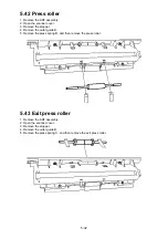
5.33 Tx cover release lever
1. Remove the Tx cover.
2. Remove the guide supporter.
3. Remove the release lever with sliding it.
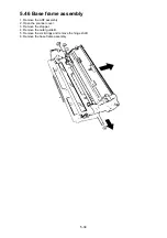
5.34 ADF interlock
1. Remove the rear cover.
2. Remove the shielding plate R.
3. Disconnect the interlock connector (P16) on the connect A PCB.
4. Remove the Tx cover.
5. Remove the guide supporter.
6. Remove the interlock.
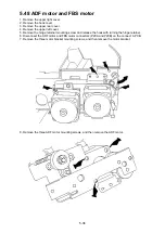
5.35 Gear cover and Gear
1. Remove the upper right cover.
Summary of Contents for OKIOFFICE 120
Page 7: ...vi ...
Page 17: ...1 10 1 7 Dimensions Dimension in mm ...
Page 23: ...1 16 1 11 ID Label Specification 1 12 Labels location ...
Page 24: ...2 1 Section2 Machine Composition 2 1 Interconnect Block Diagram ...
Page 25: ...2 2 ...
Page 87: ...3 46 Unique Switch F 7 and F 9 Factory use only ...


