2-6
Quick start
6000 Series user’s manual
To stack the PC Microcontroller, refer to the 5252MB stacking kit prod-
uct sheet enclosed with the kit. Then proceed with Step 2 in this section.
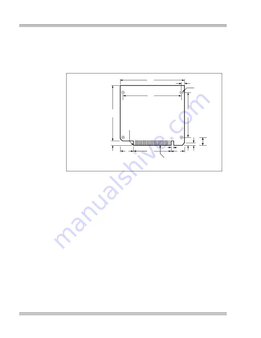
Figure 2-6
PC Microcontroller center-to-center hole dimensions
B
A
J
H
G
F
C
F
A = 4.90 in. (124,46 mm)
B = 0.20 in. (5,08 mm)
C = 3.50 in. (88,90 mm)
D = 0.10 in. at 45°, 2 PLCS
(2,54 mm at 45°)
E = 0.475 in. (4,44 mm)
F = 0.85 in. (21,59 mm)
G = 3.20 in. (81,28 mm)
H = 0.30 in. (7,62 mm)
J = 4.20 in. (106,68 mm)
K = 0.20 in. (5,08 mm)
L = 4.50 in. (114,30 mm)
A31
A1
K
D
E
BEVEL CARD EDGE, 2 PLCS
.015 in. x 45• (0,038 mm x 45•)
0.015 in. at 45• CHAMFER, 2 PLCS
(0,038 mm)
0.125 in. HOLE
(3.17 mm)
4 PLCS
L
M = .475 in (12,07 mm)
M
2. Connect the ground and 5V wires to the terminal block of the PC Micro-
controller or P2 of the stacking kit.
3. Connect one end of the VTC-9F cable to the null modem adapter. Con-
nect the other end to COM1 on the PC Microcontroller.
Note
You must use COM1 on the PC Microcontroller in order to establish a
serial communications console I/O link with your PC.
4. If your PC has a 9-pin serial connector, connect the null modem adapter
to any serial port (COM1 through COM4) on your PC. If your PC has a
25-pin serial connector, attach a 9-25 pin adapter to your null modem
adapter, then insert the matching end of the 9-25 pin adapter into the
serial port. See Figure 2-3.
Note
Refer to the PC SmartLINK manual for more information on using a
desktop COM port other than COM1.
You are now ready to transfer files between your PC and the PC Micro-
controller. Continue with the section, Establishing communications
with the PC Microcontroller in this chapter.
Summary of Contents for 6000 Series
Page 7: ...Notice to user PC 500 user s manual ...
Page 9: ...About this manual 6000 Series user s manual ...
Page 37: ...2 20 Quick start 6000 Series user s manual ...
Page 65: ...5 16 Serial ports 6000 Series user s manual ...
Page 87: ...6 22 EZ I O 6000 Series user s manual ...
Page 103: ...8 8 Analog I O 6000 Series user s manual ...
Page 119: ...14 2 PC 104 expansion 6000 Series user s manual ...
Page 133: ...16 4 Watchdog timer reset and remote reset 6000 Series user s manual ...
Page 139: ...17 6 Serial EEPROM 6000 Series user s manual ...
Page 157: ...21 2 Software utilities 6000 Series user s manual ...
Page 161: ...22 4 Troubleshooting 6000 Series user s manual ...
Page 177: ...A 16 6010 technical data 6000 Series user s manual ...
Page 215: ...D 16 6040 technical data 6000 Series user s manual ...
Page 229: ...F 2 Miscellaneous 6000 Series user s manual ...


