Radar/Chart Radar User Guide
Getting Started with Radar
2-12
65900010
Using the Cursor
Whenever the cursor is displayed, a dialog box in the bottom right of the
display gives a readout of the cursor’s position within the video circle. By
default the Cursor window gives cursor range and bearing (from own ship)
and cursor latitude/longitude, see Cursor Readout.
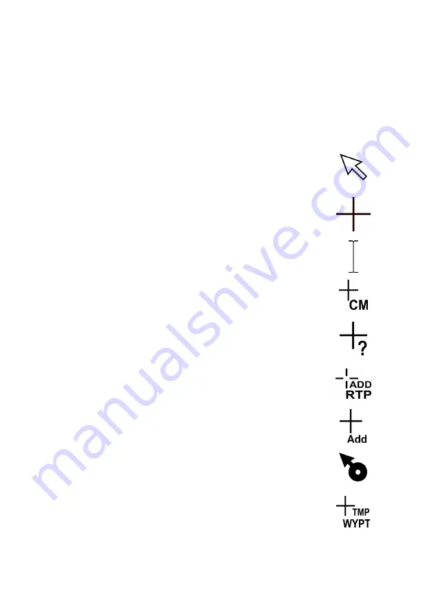
Cursor Graphics
When the cursor is over the system control areas and
background area of the radar it is displayed as a small
white arrow, referred to as the screen cursor.
As the cursor passes from the control area into the
video circle it changes to an orange cross, referred to
as the video cursor.
If an adjustable parameter is selected within a control
window, the cursor is displayed as a text entry cursor.
When
Select Points
is selected from Charts menu the
letters
CM
are added to the cursor, see Chart Match.
When
Query On
is selected from Chart Query menu, or
Add Annotation Mark
is selected from Manual Chart
Update a
?
is added to the cursor, see Chart Query
When a Return Plan is to be added, the letters ADD
RTP appear below the cursor, see Routes.
When a Polygonal acquisition zone is created, the
letters
Add
appear below the cursor, see Acquisition
Zones.
When a map offset is to be applied graphically, the
cursor changes to the following symbol, see Maps
Display Settings
When a Temporary Route Plan is created or edited, the
letters TMP WYPT appear below the cursor, see
Temporary Route Plans.
Summary of Contents for VisionMaster FT
Page 1: ...Radar Chart Radar User Guide Northrop Grumman Sperry Marine B V Part Number 65900010 ...
Page 2: ......
Page 4: ...Radar Chart Radar User Guide 65900010 ii Intentionally Blank ...
Page 24: ...Overview Radar Chart Radar User Guide 1 2 65900010 Single System ...
Page 42: ......
Page 114: ......
Page 212: ......
Page 304: ......
Page 370: ......
Page 450: ......
Page 462: ......
Page 502: ......
Page 516: ......
Page 532: ......
Page 533: ......


