18
Nobeltec InSight Radar (IR2)
Installer’s Guide
Connecting the cables
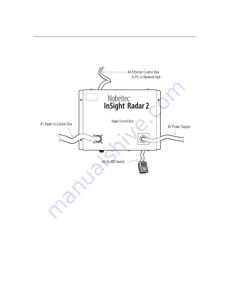
There are four cables that need to be connected.
Figure 2.9: General cabling diagram
General considerations
The cable connecting the Antenna and Control unit should already be attached to
the Antenna. By default these cables come in 10 meter lengths, however longer
cables are available and are typically installed at the factory. However, should the
need arise for you to replace the cable, use this section to understand how this
occurs. If the desired cable is attached to the antenna, you can skip this entire
section.
1) The cabl
e connecting the Antenna and Control Unit should be run separately
away from other cables such as, radio antenna feeders, power cables, etc.
Under no circumstances should it be in parallel arrangement with other cables.
These precautions are essential to avoid radio interference to/from other equip-
ment installed on the ship. If this is not possible, either cable set should be
screened with metal conduit or another form of shielding.
2) Cable should be run as short as possible but be kept within the standard length
to achieve best radar performance.
3) The copper braids of the cable must be grounded via a grounding stud in the
transceiver unit.
Hardware Installation
Summary of Contents for InSight Radar 2
Page 2: ......
Page 6: ......
Page 26: ...20 Nobeltec InSight Radar IR2 Installer s Guide Hardware Installation...
Page 64: ...58 Nobeltec InSight Radar IR2 Installer s Guide Dimensions and Weight IR2 4D Specifications...
Page 65: ...59 Installer s Guide Nobeltec InSight Radar IR2 IR2 4 3 and IR2 4 4 Specifications...
Page 67: ...61 Installer s Guide Nobeltec InSight Radar IR2 IR2 25 4 IR2 25 6 and IR2 25 9 Specifications...
Page 74: ......
Page 75: ......
Page 76: ......


