background image

(

27

)

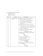
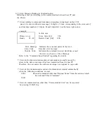
  Card Jam error in Encoder  

 Card JAM. Encode 

 Area 09    Er - 

Ad 


 Er   Ad       Symptom 

           Check/Repair 

  78


  ** 


  Card jam error in the 

  Area09

(

SN15

)

 while the 

  card is transported in         

Encoder . 


(

1

)

 Check that the card is staying in the 

    problem area.  If no card, replace 

following 

    things. 


(

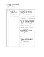
2a

)

Check there is something of which 

obstruct 

    the card transportation around the 

stacked 

    card. 

    After removing stacked card, then check 

    roller working in the Encoder. 

    If it does not work correctly , replace the 

    Encoder. 


(

28

)

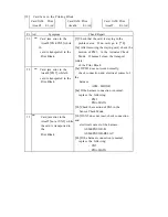
 IC R/W Access Error


IC R/W Control


Error    Er- Ad


 Er   Ad          Symptom 

        Check / Repair 

  7E


 01 


Printer received the 

command 

to quit the access to internal  

IC R/W 

(

Non contact type

 A printer is no problem. 

 See an operation manual of application 

software 

  or contact the administrator  of the total 

system.   


Summary of Contents for PR5350

Page 1: ...DIRECT CARD PRINTER PR5350 Service Manual Ver 1 0 Aug 05...

Page 2: ...on 3 Operation Panel 1 Overview 2 Description of Operation Panel 3 Internal Modes of Printer 1 Operation of Service Mode 2 Structure of Service Mode menu 3 Description of Service Mode 4 Structure of S...

Page 3: ...ion for the message on the LCD and meeting of recovery 2 Checking and repairing of the troubles 3 Troubles on communication with PC 2 Errors which can not be checked on the LCD panel 3 Card JAM Locati...

Page 4: ...n heat transfer printing for color image and heat melted ink transfer printing system for characters black and protective overlay With standard built in Flip Turn Block both side printing is possible...

Page 5: ...s R G and B Output 256 grayscale control for each colors C M and Y Printing Size Max 85 5mm card longitudinal 54mm card transverse direction Printing Arrangement Area Max Entire area Printing Speed 45...

Page 6: ...bottom of the pile and automatically transported in the printer A weight plate is provided to ensure the positive feeding of cards when the remaining cards becomes low Card separation is done by the...

Page 7: ...of the head to maintain uniform contact to the card The thermal head is assembled in one independent unit so that the replacement is made very easy Also a user can replace the print head and ribbon at...

Page 8: ...controls the thermal print head according to the image data Interface Board PBA I F SCSI or PBA IF USB Controls the SCSI or PARALLEL interface For SCSI It has connector and terminator switch for SCSI...

Page 9: ...Flash Memory IC8 A memory of 4 M bytes for storing the firmware It can be downloaded through the SCSI or USB interface SRAM IC9 1 M byte memory to be used for cash memory of CPU IC1 EEPROM IC4 4K byte...

Page 10: ...nnectors on the interface board Also there is a connector for connecting the optional device Serial interface driver IC4 Translates the signal of CPU to RS422 level for the communication with the atta...

Page 11: ...printing and clearing errors LCD IC1 LCD panel of 16 characters 2 lines Displays the condition of the printer setting and changes of values error messages etc LED1 LED3 Indicate the Printer condition...

Page 12: ...fed taking up side SN10 Optical Sensor Detection of mark on the ribbon SN11 Optical Sensor Detection of print head position SN12 Optical Sensor Detection of print head position SN13 Micro switch Dete...

Page 13: ...ting magnetic field Other than above use general caution for setting up other OA equipments and choose proper place with proper environment For further details please read operation manual 2 1 2 Space...

Page 14: ...ters To ensure stable operation within 4 meters is recommended Note 2 Please use the SCSI II specification high impedance cable In case of daisy chain connection operation may become unstable unless a...

Page 15: ...o switch off Appearance of Terminator switch 3 Setting SCSI ID Number The SCSI ID number can be freely selected from 0 to 7 through the operation panel of the printer Default ID setting is 4 Note 1 Do...

Page 16: ...equipped with B type connector Note 1 Turn OFF power switches of the Printer PC and all units when connecting the cable Note 2 On the backside of the Printer OPTION CONNECTOR located next to USB conne...

Page 17: ...ed Step 4 Insert the ENCODER into the encoder space of the printer with connecting the two harnesses from the printer Step 5 Fix the ENCODR with the screw of which was removed in Step3 Step 6 Put the...

Page 18: ...for PR5350 as following 1 Normal mode Display the current operating status such as error of the Printer during the print operation The Printer is in this mode when the power is turned ON Refer to Ope...

Page 19: ...display changes from Input Command to Service Mode 4 Release the MENU key Moving in the Same Directory To move in the directory press MENU key to change the menu MENU will change in the set order whe...

Page 20: ...uto Adjustment EXE sub menu EXE Adj Start User Menu Config Return to Parent IC R W Test EXE sub menu Menu CLR EXE EXE Entry Eject Encoder Check Return to Parent EXE sub menu Menu CLR EXE IC R W Check...

Page 21: ...sub menu EXE Test Print Menu CLR EXE F Turn Angle Adj Color Adjustment EXE sub menu EXE Test Print Return to Parent Color Adjustment LCD Adjustment Menu CLR EXE EXE Test Print Return to Parent Return...

Page 22: ...tr PM3 EXE sub menu EXE DOWN EXE CW HDRV Print Mtr PM3 Headup Mtr DM1 Print Mtr PM3 EXE sub menu EXE UP EXE CCW LDRV Card Pass Test Return to Parent Return to Parent EXE sub menu Menu CLR EXE Menu CLR...

Page 23: ...ment for Black print Zero Adj Clear Pre heat Adjustment for Clear over coat print Clear key Decrement Value Min value 7 Exe key Increment Value Max value 7 According to a card In case that color come...

Page 24: ...ht edge of a card Data Cut Enable Set the data cut function enable or disable when a printer detect the right edge of a card Clear key N A Exe key enable ON or disable OFF Note Use this Adjustment whe...

Page 25: ...ance between sensor and print head 0 5mm digit Clear key decrement value Min 9 Exe key increment value Max 9 Cyan Black Over Coat ZZ ZZ mm Appearance of the ribbon After Printing XX YY YYmm MENU CLEAR...

Page 26: ...case of card picked up Pickup Angle Adj Adjustment the value to revise the angle of the F T when card picked up Clear key N A Exe key Start auto adjustment function Note Adjust the angle correctly Oth...

Page 27: ...of sensor for ribbon mark detection Clear key Decrease the amount of light Exe key Increase the amount of light Auto adjustment menu for ribbon detection sensor Auto Adjustment Auto Adjustment for rib...

Page 28: ...he print head to ready position DOWN to move the print head to print position UP to move the print head to the position where ink ribbon can be changed Clear key stop Exe key start Action of supply ro...

Page 29: ...W 300mm s Clear key stop Exe key start Action of card transportation roller at print block Print Mtr PM Activate the rollers at print block in limited time CCW HDRV High speed CCW 300mm s CW HDRV High...

Page 30: ...right side of the printer Clear key N A Exe key select ejecting position Setting number of card transportation test Print Number Setting number of times for test Clear key decrement number min 1 Exe...

Page 31: ...printer has fed cards Writing data is as follows ISO Track 1 ISO_TRACK_1_ENCODE_TEST _ARTLAND_COLOR_PRINTER_PR5350_ TOTAL_NO ____ ISO Track 2 12345678901234567890123456789 ISO Track 3 1234567890123456...

Page 32: ...usting transferring position horizontal direction unit of adjustment 0 2mm Clear key decrement value min 10 Exe key increment value max 10 Sensor adjustment Sensor Adj auto adjustment of ribbon detect...

Page 33: ...Displays Total count at every 10 errors Number of error occurred display Error Code rate Displays number of the error occurred in order aa error code bb detail code cc total number of error occurred...

Page 34: ...r transportation Cleaning every 10000 fram es Cleaning every 10000 frames Cleaning as required Symptom Poor transportation Trouble shoot Philips screw driver Soft Cloth Alcohol Philips screw driver So...

Page 35: ...Transport Rollers in Flip Turn Module Open Top Cover and rotate Turn Module so that the rollers come to the position where the cleaning can be done easily This operation is done with the green knob i...

Page 36: ...torque and has friction with shaft grease is applied at the factory Although further greasing in not required for normal usage grease should be applied in case following parts are replaced for some re...

Page 37: ...Main Board onto the Printer 7 screws and connect all harnesses Step 6 Make sure that the SW1 is set as NORMAL MODE Step 7 Raise the MAIN BOARD PLT and fix with screws 4 screws Step 8 Attach R COVER S...

Page 38: ...ng on the print result X Unnecessary Items to be set in the User Mode Main Board Replacement only Setting Items Setting Ribbon Type Setting the ribbon type to be used Color Adjustment Setting the colo...

Page 39: ...tern H again and confirm the h and v dimensions Repeat the above if necessary Note 1 If h v is smaller than 0 5mm increase the setting value If h v is larger than 0 5mm decrease the setting value Note...

Page 40: ...ing table If the distance is dot should also be d o t m m d o t m m 0 0 00 26 2 20 1 0 08 27 2 29 2 0 17 28 2 37 3 0 25 29 2 46 4 0 34 30 2 54 5 0 42 31 2 62 6 0 51 32 2 71 7 0 59 33 2 79 8 0 68 34 2...

Page 41: ...densities of two positions to the same as the least dense position Step 3 Print Test Pattern H again and check the density of the three positions Adjust again if necessary Note 1 Use density meter to...

Page 42: ...f the starting portion of Protective Layer is not printed increase value of Clear Caution Do not set too large value because it may cause a trouble Step 4 Print Test Pattern J again to check the densi...

Page 43: ...is too thick and lines touches each other decrease the value Step 3 Print Test Pattern E again and check the print condition Adjust again if necessary Note 1 Start adjustment with the current value va...

Page 44: ...structed in paragraph 3 Note Adjust the sensor output level at where the external light will not affect When measuring the output voltage of the sensor with volt meter use the meter at 0 1V range 1 Au...

Page 45: ...ins on the Main Board for checking the sensor voltage with tester SN10 Detection of mark on the Ribbon Test Pin TP88 SN10PT Lighted 1 0V or less Yellow detection Blocked 3 0V or more Bk detection Note...

Page 46: ...uit diagram and if defective connection is found replace the harness Check mounting of the light sources and sensors If incorrect mounting angle of sensor or loose screw is found correct the mounting...

Page 47: ...ent in Service Mode Step 2 To make the density higher press EXE key To make the density higher press EXE key 5 4 Adjustment for Card Thickness Adjustment of Gap of Separation Gate Step 1 Open cover of...

Page 48: ...two digit of details code Ad On the LCD panel it is shown with error message 16 digits x 2 lines corresponding to the error code and four digit numbers 2 digits Er and 2digits Ad on the lower right c...

Page 49: ...head is lifted and the ribbon cassette can be removed It is possible to transfer the data from the host computer and print Please wait Initializing Printer is being initialized Please wait Now printi...

Page 50: ...e is no card Set the cards in the card hopper and press CLEAR key Front Cover is Open CLEAR key is pressed while the Front Cover is open Close the Front Access Cover and press CLEAR key Top cover is o...

Page 51: ...n the card hopper and press CLEAR key Ribbon Empty 20 Printing Ribbon is finished Set new ribbon in the printing block and press CLEAR key Front Cover is Open 10 01 Front Access Cover is open Check th...

Page 52: ...y Card Jam Feeder Area 42 A card remains at SN02 and can not pass to F T unit Take the card out by hands Card Jam F Turn Area Card transportation error in the flip turn block Press CLEAR key If imposs...

Page 53: ...of the printer system Most of those troubles needs the check and repair by the service person LCD Display Status Recovery Method Service Man Call error Code There is an unrecoverable error in the prin...

Page 54: ...CB It may cause a trouble As it is dangerous please carefully operate the operation panel not to move into other mode than the sensor check mode Card Jam Errors are detected by the sensors located alo...

Page 55: ...e mark on panel to panel 04 could not detect a unique mark 22 05 Abnormal cycle of unique mark Ribbon Type Incorrect 23 Ribbon transportation time out Error code 30h 3Fh Relation to hardware on print...

Page 56: ...M Feeder Area01 Card JAM Feeder Area01 Card JAM Feeder Remove Card JAM F Turn Area02 Card JAM F Turn Area03 Car d JAM F Turn Area04 Card JAM F Turn Area08 Card JAM F Turn Remove Card JAM F Turn Lost C...

Page 57: ...Card JAM Print Area06 Card JAM Print Area07 Card JAM Print Remove...

Page 58: ...ror code 70h 78h Relation to Magnetic encoder unit Error Message Er Code Ad Code Description 01 03 Data sending error with Printer En unit 70 0F Data receiving error with Printer En unit 71 10 16 Sequ...

Page 59: ...ption BC 01 04 Error with specifying on IF Board 01 Error with DMA control DRAM CPU 1 Error with DMA control CPU DRAM C0 2 Error with DMA control DRAM clear C1 01 02 Time out error when clearing flash...

Page 60: ...rness ASM I F SW 3 If the harness connection is not normal replace the following SN13 PBA MAIN 2 Top Cover Open Top Cover is Open Er Ad Er Ad Symptom Check Repair 11 01 Top Cover is left open If it be...

Page 61: ...ecomes error despite the cards are set see the Check Repair section 1 Check the reaction of SN1 by using Sensor Check Mode 2 If the sensor does not react normally check the connection and electric con...

Page 62: ...nsor Check Mode If the sensor does not work correctly go 2b or 3b mentioned below 2a The sensor works correctly check the connection and electric contact of the harness for DM1 ASM MOTOR 3a If the har...

Page 63: ...c contact of the harness of DM1 ASM MOTOR 3a If the harness connection is normal replace the following Ribbon Cassette DM1 PBA MAIN 2b Check connection and electrical contact of harnesses of SN18 ASM...

Page 64: ...ur in spite of Ribbon is set correctly see the Check Repair section 1 Check whether there is a damage on the ribbon 2 Adjust the sensor SN10 in the Sensor Check Mode If impossible to adjust check the...

Page 65: ...ASM MOTOR 6a If the harness connection is normal replace the following PM1 PBA MAIN 4b Turn angle sensors are doubted Check connection and electrical contact of the harness ASM SENSOR A 5b If the har...

Page 66: ...normally go to 2b 2a DM1 is doubted Check connection and electrical contact of the harness ASM MOTOR 3a If the harness connection is normal replace the following DM1 PBA MAIN 2b The head position sen...

Page 67: ...ange 1 Check connection and electric al contact of the harness of the thermal head ASM HEAD 2 If the harness connection is normal replace the following Thermal Head PBA MAIN 38 02 Temperature around t...

Page 68: ...st Data Code Error Er Ad Er Ad Symptom Check Repair 3E 01 The information of a resister is not registered 3F 01 The information of a resister is broken 1 Download the data of which serial number is as...

Page 69: ...tor Check Mode If the motion is normal clean the feed rollers in the card feeding block and adjust the separation gate 3a If it does not work normally check the connection of harness ASM MOTOR 4a If t...

Page 70: ...or Code 43 part 2a Check the motion of PM1 in the Actuator Check Mode If the motion is normal clean the feed rollers in the card feeding block and adjust the separation gate 3a If it does not work nor...

Page 71: ...s not ready to receive the card 1 Check that the card is staying at the SN2 If there is not the card go to 2b 2a Adjust the separation gate 2b Check the reaction of SN2 in the Sensor Check Mode 3a If...

Page 72: ...41 part 2a After removing the card check the motion of PM2 in the Actuator Check Mode If normal clean the transport rollers in the flip turn block and Cleaning Roller then adjust the separation gate 3...

Page 73: ...ng the card check the motion of PM2 in the Actuator Check Mode If normal clean the transport rollers in the flip turn block 3a If PM2 does not work normally check connection and electrical contact of...

Page 74: ...ion of PM2 PM3 in the Actuator Check Mode If normal clean both the transport rollers of Flip Turn block and the Print Block 3a If PM2 and PM3 does not work normally check connection and electricalcont...

Page 75: ...rn block Check that there is Encoder Check menu in the service mode If there is not Encoder Check menu the printer does not recognize the Encoder Then see section 6 2 Errors which can not be checked o...

Page 76: ...angle of Flip Turn unit is positioned correctly toward Feeder Block or Print Block or Magnetic Encoder Block If it is not positioned correctly see the Error Code 31 part 2b Check the reaction of SN3...

Page 77: ...ot the card go to b 2a Check the reaction of SN3 4 15 in the Sensor Check Mode 3a If SN3 4 15 does not react check the connection of the harness SN3 4 ASM SENSOR B SN15 when encoder connected ASM ENC...

Page 78: ...ck the motion of PM2 PM3 in the Actuator Check Mode If normal clean the transport rollers of Flip Turn block and the Print Block 3a If PM2 and PM3 does not work normally check connection and electrica...

Page 79: ...that the card is staying in the problem area If no card go to b 2a After removing the staying card check the motion of PM3 in the Actuator Check Mode If normal clean the transport rollers of the Prin...

Page 80: ...SN4 SN5 do not react check connection and electrical contact of the harness SN4 ASM SENSOR B SN5 ASM SENSOR B ASM SENSOR RELAY 4b If the harness connection is normal replace the following SN4 SN5 PBA...

Page 81: ...ON the power switch 2 If this symptom repeats there is some problem with the encoder 23 Magnetic Encoder Writing Error Encoder Write Error Er Ad Er Ad Symptom Check Repair 01 07 A writing error has oc...

Page 82: ...t depends on the settings in the printer and or operation of an application to put the card surface of which has magnetic stripe side up or down Check the magnetic stripe of the card meets a writing f...

Page 83: ...Mode If normal clean the transport rollers of the Encoder Check the transport roller working normally If it does not work normally replace the Encoder 3a If PM2 does not work normally check connectio...

Page 84: ...hing of which obstruct the card transportation around the stacked card After removing stacked card then check roller working in the Encoder If it does not work correctly replace the Encoder 28 IC R W...

Page 85: ...oard C0 01 1 2 Some abnormal status has detected when finishing to access to image memory C1 01 02 Some abnormal status has detected when finishing to access to flash memory 2D 01 02 03 Some abnormal...

Page 86: ...Error Code Encoded error message Details Code Indicated the command received which has caused the error as shown as Error Message Refer to the Command Specification regarding the details Errors in th...

Page 87: ...Field in CDB Er Ad There is error in the description block of the received SCSI command 1 Check if the command description block meets the contents of the Command Specification 2 Clear the error by pr...

Page 88: ...accordance with the command specification Also check the setting of the number of byte of the transmitted data 2 Press CLEAR key to clear the error and transmit the command again 89 Invalid field in...

Page 89: ...ification 2 Clear the error with CLEAR key and transmit the command again 94 Multi Parameter Received Er Ad An error that received Print Command repeatedly while receiving request plural times to flip...

Page 90: ...received magnetic encode data exceeds the standard 1 Check whether the type and number of the magnetic encoding characters meets the standard 2 Clear the error with CLEAR key and transmit the command...

Page 91: ...transfer byte of magnetic encode or barcode and the data are transmitted correctly 2 Clear the error with CLEAR key and transmit the command again A9 Character Error in Encode Er Ad Magnetic encode da...

Page 92: ...boards below PBA MAIN PBA IF 3 If the problem is not gone after done above call your dealer BA Download Ap Abort Er Ad Downloading is interrupted by application soft ware 1 Reboot the printer and dow...

Page 93: ...unit into the printer unit Connecting the optional units Removing covers of the optional units Symptom Condition Check Repair AC power is not supplied 1 Check if the power supply matches specificatio...

Page 94: ...rdware check function in the serviceman mode Image defectives such as uneven color or lost lines etc when printing the image and characters Defective circuit board 1 Turn OFF the power and replace the...

Page 95: ...Defective circuit board 1 Turn OFF the power replace the following and check operation PBA IF PBA MAIN 6 3 Card JAM Location...

Page 96: ......

Page 97: ...esistData is not Loaded 1E 01 Resist data of the head is not loaded on the printer Download the resist data of the head 9 Other particular error In case of dual side printing If a printing process is...

Reviews: