?
In the memory on the Main Board, the adjustment values for the printing operation are
stored. Therefore, when replacing the main board, the adjustment in the following steps
are necessary. It is advisable to memorize these adjustment values before beginning the
replacement work so that the values can be used for the new board.
?
If there is a difference in the print quality between before and after there placement of
the thermal head, adjust as following.
?
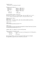
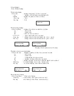
For the details of the operation panel, please refer to Section 3, Operation Panel.
?
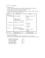
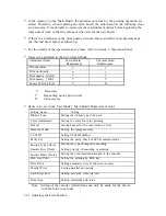
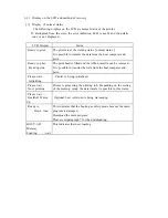
Items to be adjusted in the Serviceman Mode
Adjustment Items
Main Board
Replacement
Thermal Head
Replacement
Print position
?
?
Print uniformity
?
?
Print density
(
Color
)
?
?
Print density
(
BK
)
?
?
Sensor
(
SN10
)
level
?
X
?
: Necessary
?
: Depending on the print result
X
: Unnecessary
?
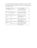
Items to be set in the User Mode
(
Main Board Replacement only
)
Setting Items
Setting
Ribbon Type
Setting the ribbon type to be used
Color Adjustment
Setting the color for color printing
Buzzer
Setting buzzer for the occurrence of error
Memory Mode
Setting the image memory
SCSI ID
Setting SCSI ID number
Parity Set
Setting the parity check of SCSI communication
Encode Type
(
Note
)
Setting the type of magnetic encoding
Encode First
(
Note
)
Setting priority of encoding or printing
Encode Mode
(
Note
)
Setting the card insertion direction to the encoder
EXE Key Print
Setting the printing by EXE key
Print Retry
Setting automatic retry at the error recovery
Parallel Print
Setting parallel processing
Card Eject Face
Setting card side when ejected
Print Area
Setting maximum print area
Note: Setting of the encoder related items can only be made for the device
with the built-in encoder.
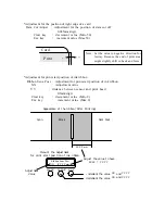
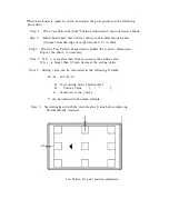
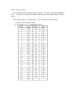
5.2.1 Adjusting the Print Position


