3
)
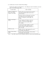
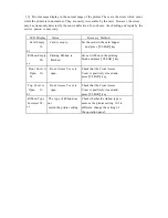
Countermeasure for the Abnormal Sensor Output
If the sensor output as described in 2
)
is not obtained, locate the defective part and
repair in the following procedure.
Possible Defect
Check and Repair
Check contcts of all connectors which connects
the boards with light sources and sensors to
the Main Board.
Defective connection of
harness and Printed
Printed Circuit Board.
Check the contact of each harness with circuit
tester following the circuit diagram and if
defective connection is found, replace the
harness.
Check mounting of the light sources and
sensors. If incorrect mounting angle of
sensor or loose screw is found, correct
the mounting.
Defective mounting of
sensor.
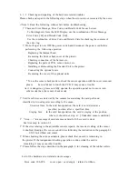
Conf irm that the light emitting face and the
receiving face of the sensors are facing
directly and there is nothing in between to
block the light.
Defective sensor.
Replace the sensor
(
light emitter and receiver
)
and confirm normal operation.
Defectiv e Main Circuit
Board.
Replace the Main Circuit Board
(
PBA- MAIN
)
and confirm normal operation.
Note: Turn OFF the power when checking connection of harness and replacing parts.


