background image

8 - 19

4. Go back to the MENU screen.

Press 

.

5. Go back to the Layout screen.

Press 

 twice.

8.10 PD Adjustment

If the PD value input on the Layout screen does not agree with the PD of the finished lens, adjust
the PD amount of the finished lens by the following procedure.

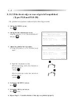
1. Call up the MENU screen.

Press 

.

2. Call up the PD adjustment screen.

Align the pointer (

) to “PD adjustment” and

press 

.

3. Adjust the PD.

Input the compensation value with 

 or 

.

Adding the value will increase the finished PD.
e.g.
When the finished PD becomes 65.5 by inputting PD: 66.0, add 0.50 to the present value.

4. Go back to the MENU screen.

Press 

.

5. Go back to the Layout screen.

Press 

 twice.

㧖㧖㧖㧖㧖㧖㧖㧖㧖㧖㧖㧖㧖㧖㧖㧖㧖㧖㧖㧖㧖㧖㧖㧖㧖㧖㧖㧖㧖㧖㧖㧖

ޓ

ޓ

㧖ޓޓޓޓޓޓ㧸㨑㨚㨓㨠㨔ޓ㧾㧦㧝㧠㧟㧚㧣㧤ޓ㧸㧦㧝㧠㧟㧚㧣㧢㧖
㧖㧖㧖㧖㧖㧖㧖㧖㧖㧖㧖㧖㧖㧖㧖㧖㧖㧖㧖㧖㧖㧖㧖㧖㧖㧖㧖㧖㧖㧖㧖㧖㧖

ޓޓޓ

ޓψޓ㧼㨞㨛㨏㨑㨟㨟ޓ㨏㨛㨡㨚㨠㨑㨞ޓޓޓޓޓޓޓޓޓޓޓޓޓޓޓ

ޓޓޓ㨃㨔㨑㨑㨘ޓ㨐㨞㨑㨟㨟㨕㨚㨓ޓޓޓޓޓޓޓޓޓޓޓޓޓޓޓޓ
ޓ

ޓ

ޓ

ޓ

ޓ

ޓޓޓ㧿㨕㨦㨑ޓ㨍㨐㨖㨡㨟㨠㨙㨑㨚㨠ޓޓޓޓޓޓޓޓޓޓޓޓޓޓޓ
ޓ

ޓ

ޓ

ޓ

ޓޓޓ㧮㨑㨢㨑㨘ޓ㨍㨐㨖㨡㨟㨠㨙㨑㨚㨠ޓޓޓޓޓޓޓޓޓޓޓޓޓޓ
ޓ

ޓ

ޓޓޓ㧭㨄㧵㧿ޓ㨍㨐㨖㨡㨟㨠㨙㨑㨚㨠ޓޓޓޓޓޓޓޓޓޓޓޓޓޓޓ
ޓ

ޓ

ޓ

ޓ

ޓޓޓ㧼㧰ޓ㨍㨐㨖㨡㨟㨠㨙㨑㨚㨠ޓޓޓޓޓޓޓޓޓޓޓޓޓޓޓޓޓ

㧖㧖㧖㧖㧖㧖㧖㧖㧖㧖㧖㧖㧖㧖㧖㧖㧖㧖㧖㧖㧖㧖㧖㧖㧖㧖㧖㧖㧖㧖㧖㧖
㧖 ޓ ޓ ޓ ޓ ޓ ޓ ޓ 㧼 㧰 ޓ 㨍 㨐 㨖 㨡 㨟 㨠 㨙 㨑 㨚 㨠 ޓ ޓ ޓ ޓ ޓ ޓ ޓ ޓ 㧖
㧖㧖㧖㧖㧖㧖㧖㧖㧖㧖㧖㧖㧖㧖㧖㧖㧖㧖㧖㧖㧖㧖㧖㧖㧖㧖㧖㧖㧖㧖㧖㧖
ޓޓޓޓޓޓޓޓޓޓޓ㧖㧱㨄㧵㨀ޓ㧦ޓ㧼㨞㨑㨟㨟ޓ㧿㧱㧸㧱㧯㨀ޓ

ޓψ㧼㧰ޓ㨏㨛㨚㨟㨠㨍㨚㨠ޓޓޓޓޓޓޓޓޓޓޓޓ㧦㧗㧜㧚㧡㧜㨙㨙

ޓޓ㧲㨞㨍㨙㨑ޓ㨀㨕㨘㨠ޓ㧭㨚㨓㨘㨑㧔㨒㨘㨍㨠㧕ޓ㧦ޓ㧡㧚㧜qޓޓ

Summary of Contents for LE-9000DX Express

Page 1: ...NIDEK PATTERNLESS EDGER LE 9000EX Express LE 9000DX Express OPERATOR SMANUAL...

Page 2: ...ku Tokyo 101 0051 Japan Telephone 03 3288 0571 Facsimile 03 3288 0570 Telex 2226647 NIDEK J NIDEKINCORPORATED 47651 Westinghouse Drive Fremont California 94539 U S A United States Agent Telephone 510...

Page 3: ...ocedures safety precautions specifications and information about accessories and maintenance IEC and UL standards are applied in this manual This manual is necessary for proper use Especially the safe...

Page 4: ...E 9000EX Express LE 9000DX Express 4 4 4 3 2 1 Inputting the height from the lens outline 4 8 4 3 2 2 Layout of bifocal lenses 4 9 4 3 2 3 Layout of progressive power lenses 4 10 4 3 2 4 Inputting eye...

Page 5: ...Cup 4 55 4 9 Treatment after Daily Use 4 56 4 10 Daily Checks 4 57 4 10 1 Daily check before use 4 57 4 10 2 Daily check after use 4 58 4 11 Periodical Check 4 59 5 OTHER FUNCTIONS 5 1 5 1 Process Co...

Page 6: ...3 Adjusting the groove depth LE 9000EX Express only 8 28 8 12 3 1 Groove depth is not made as designated LE 9000EX Express only 8 28 8 12 3 2 Groove depth is not even LE 9000EX Express only 8 29 8 13A...

Page 7: ...ata and the processing unit processes the lens into a desired shape Several kinds of processing wheels are provided in the processing unit and therefore this instrument selects the most suitable wheel...

Page 8: ...lectric shock The inside of the instrument includes high voltage circuit Do not take off the cover This symbol on the power switch indicates that the power is ON This symbol on the power switch indica...

Page 9: ...processing a lens Spray including processing waste may damage your eyes In case abnormal conditions such as cracks or bare areas on the processing wheel have been found stop using the instrument immed...

Page 10: ...ey will become damp and may cause a short circuit or a fire Plug the power cord correctly until its prongs are fully inserted into the socket If the instrument is used with an insecure connection a fi...

Page 11: ...ransport CAUTION When moving the instrument ask somebody to help You may hurt your back or may fall down if you do it alone When moving the instrument hold A and B for both of the right and left sides...

Page 12: ...ent Vibrations and noises may be produced and normal processing may not be performed Use a stage whose size is larger than the measurements of the figure on the right Also set the adjuster at the foot...

Page 13: ...settles on the prongs of the plug it will become damp and a short circuit or a fire may occur Clean the processing unit after the last use of the day If it is left for some days after it is used the...

Page 14: ...ed dressing stick and your hand may get hurt Be sure to wear protective glasses for wheel dressing Spray including processing waste may damage your eyes Never dress the roughing wheel for plastic lens...

Page 15: ...r supply pipe may be clogged Never use an organic solvent such as paint thinner to clean the exterior of the instrument This could damage the surface 2 8 Disposal NOTE Follow local governing ordinance...

Page 16: ...2 8 2 9 Labels The following labels provide safety information about each part Front view Rear view or or or Only for 115 V AC regions...

Page 17: ...2 9 or or Top view...

Page 18: ...e it is hazardous In addition open the soundproof cover after making sure that the wheels have stopped completely Stop key This is the key to stop processing Processing can be stopped immediately unde...

Page 19: ...2 11...

Page 20: ...C interface connector Connector for barcode scanner Outlet for pump 1 Outlet for pump 2 Power switch Contrast control Inlet Cooling fan Soundproof cover Cabinet Small articles box Display panel Drawer...

Page 21: ...o clear the screen RS 232C interface connector This is a connector to which an external device is connected This connector conforms to RS 232C interface Traced data needs to be read from an external d...

Page 22: ...3 3 Processing unit Feelers Chamber cleaning nozzle Adapter Lens clamp Feedwater nozzles Wheels Grooving wheel Chamfering wheel...

Page 23: ...Chamber cleaning nozzle During processing of a lens the water sup plied by the nozzle washes processing waste away before they disperse within the processing chamber Water prevents the processing wast...

Page 24: ...flat edging PNT EX Auto grooving LE 9000EX Express only NYL AUT Guided grooving LE 9000EX Express only NYL GUI EX lens grooving LE 9000EX Express only NYL EX Control panel for processing unit Selects...

Page 25: ...cursor Switches the screen in the following or der Layout screen MENU screen Param eter exchange mode screen This key does not function during process ing 1 Stops processing Starts processing 1 When t...

Page 26: ...between the right and left rim centers 30 00 99 50 mm incre ment 0 50 mm The rim centers are cal culated by the boxing system It is possible to input DBL by aligning the cursor to FPD and pressing Pup...

Page 27: ...EX or Blank Blank indicates flat edging without a groove Polishing indication Indicates the polishing mode Frame changing indication Indicates the simple frame changing mode R L indication Indicates t...

Page 28: ...creen is shown while a groove is simulated LE 9000EX Express only 48 48 Groove sectional view Groove curve Groove dip point Groove depth Groove width Sectional view position line Edge s thickest point...

Page 29: ...or backward Adjust the bevel tip point diagonally opposite to the boxing center of the tilt base position The value can be changed in 0 1 mm increments Tilt base position This is the base bevel positi...

Page 30: ...ance PD height of the optical center and the parameter setting related to data communication are done Barcode screen This screen is available only when the edger is connected to the optional barcode s...

Page 31: ...essive power lenses p 4 12 4 4 2 Blocking in passive mode p 4 13 4 4 3 Blocking bifocal lenses p 4 14 4 5 Processings 4 5 1 Beveling p 4 17 4 5 1 1 Auto processing mode p 4 20 4 5 1 2 Guided processin...

Page 32: ...4 2 4 6 Checking the Lens Size 4 6 1 Checking the lens size p 4 53 4 6 2 Retouching lenses p 4 53 4 7 Processing the Opposite Lens p 4 55 End of processing Power OFF...

Page 33: ...he power cord into a wall outlet CAUTION Do not put too much load on one electrical outlet It may cause a fire Prongs of the plug must be fully inserted into the socket Incomplete connection may cause...

Page 34: ...fety bevel size cannot be specified on the LE 9000EX Express Safety bevels of the same size will be made even if the chamfering mode Small Middle Large Special is specified Chamfering cannot be perfor...

Page 35: ...mode The processing mode can be selected with or See the table on the right For adjusting a bevel or groove position Select the GUI mode For processing an EX lens Select the EX mode For processing a...

Page 36: ...de of A 2 Selection of Blocking p A 2 4 Input each item of data of the lens layout Input values of FPD 4 PD and height of the optical center 1 Input the PD value on the prescription Align the cursor C...

Page 37: ...t is recommended to use a lens which is 2 3 mm longer in diameter for cases where the optical center and the center of the lens are not the same When the mark of the optical center becomes When the la...

Page 38: ...the lens outline BT Height from the point level with the optical center straight down to the lowest point on the lens outline 2 Input the height of the optical center e g If the height from the optica...

Page 39: ...or near vision at PD 4 Align the cursor to and select or with 5 Input the segment at the center of the top line PD Height from the center point on the top line of the segment straight down to the poin...

Page 40: ...to the LE 9000EX Express LE 9000DX Express p 4 4 2 Select ACT Active for the layout mode 3 Input the prescribed PD at PD 4 Input the height of the eye point marked on the dummy lens See 4 3 2 1 Inputt...

Page 41: ...n dummy lenses as the optical center 1 Align the cursor to FPD and press twice The display changes as shown in the right figure The mark in the traced outline shows the position of the eye point The d...

Page 42: ...rpose 2 Block the convex surface of the lens with a suction cup The cup has the blocking direction as shown with the top mark Be careful not to block the wrong side up especially for dual tone colored...

Page 43: ...tical center as indicated 1 Mark at the optical center of a lens with a lensmeter See Step 1 of 4 4 1 Blocking in active mode p 4 12 2 Block the convex surface of the lens with a suction cup Decenter...

Page 44: ...lens at the position 5 mm above and 5 mm outside from the top line center of the segment with a lens cup When using the NIDEK centering device CE 1 NOTE The edger is factory configured so that a lens...

Page 45: ...high power plus monofocal lens Low power minus monofocal lens 4 6 or 5 5 Medium power minus monofocal lens 3 7 or 4 6 High power minus monofocal lens 3 7 7 Processing mode Type of lens CRV FRNT REAR R...

Page 46: ...e p 4 27 Cataract lenses cannot be processed in the auto processing mode Process a cataract lens with the bevel curve profiling the rear surface in the guided processing mode See 4 5 1 2 Guided proces...

Page 47: ...ZYL AUT 2 Set a lens to the adapter in the processing unit Align the top mark on the suction cup with that of the adapter and insert the suction cup firmly Then press to fix the lens NOTE To attach a...

Page 48: ...Only when is selected LE 9000EX Express only Processings are complete The Layout screen returns When the screen changes to the Bevel simulation screen in Step the sectional view position line rotates...

Page 49: ...eel change the position where the plastic lens contacts the roughing wheel To adjust the contact position press or during roughing The contact position with the wheel will shift to the right The conta...

Page 50: ...ng a lens If the soundproof cover is opened during processing the instrument will not stop Spray including processing waste may damage your eyes 4 Press Lens shape measurement The screen changes to th...

Page 51: ...ue produces the same bevel curve that is processed in the auto processing mode The curve of the front base curve FRNT rear base curve REAR or ratio will be selected Specified curve value Front base cu...

Page 52: ...CRV A5 0 PNT 0 6 This shows that the bevel was moved 0 6 mm toward the rear surface parallel to itself while the bevel curve value was 5 0 NOTE In order to avoid the bevel being off the lens edge be...

Page 53: ...s dropped it may contact the turning wheels and its scattering may cause an injury It is also possible to switch the processing mode to the guided processing mode even in the middle of auto processing...

Page 54: ...screen and the instrument stops See Steps 1 5 of 4 5 1 2 Guided processing mode p 4 20 2 Adjust the bevel position 1 Press or to move the sectional view position line to the base position and check th...

Page 55: ...ar surface parallel to itself The whole bevel moves toward the front surface parallel to itself next to the value shows that the bevel was moved forward next to the value shows that the bevel was move...

Page 56: ...cattering may cause an injury 5 When subsequently processing the other lens by switching R or L the former setting for the lens will be shown on the screen If one lens is processed with the tilting fu...

Page 57: ...hold the convex surface of a lens securely enough The cup may move during blocking 1 Check the processing conditions MTL or CEL ZYL EX 2 Set a lens to the adapter in the processing unit See Step 2 of...

Page 58: ...it but leave it as the rear base curve REAR The specified curve front base curve or Ratio is not appropriate for an EX lens to process the bevel properly 6 Start processing Press Rough processing Fin...

Page 59: ...de The figure by the dotted line illustrates the side view of the EX lens which is processed with the tilting function As illustrated the bevel on the thick upper part of the lens is moved toward the...

Page 60: ...rom the frame center Tilt base position If the lens edge is thin change the bevel tip point PNT to move the bevel backward as much as possible If the lens has enough width place the bevel tip point at...

Page 61: ...See Step 2 of 4 5 1 1 Auto processing mode 3 Close the soundproof cover Processing does not start even if is pressed unless the soundproof cover is closed WARNING Be sure to keep the soundproof cover...

Page 62: ...the wheels have stopped completely Release the chuck by pressing after making sure that the wheels have stopped completely When the chuck is released before the wheels have stopped completely if a len...

Page 63: ...ooving is performed After retouching grooving is performed If GUI has been selected in Step 1 the screen will change to the Simulation screen and stop temporarily Check the groove section and adjust t...

Page 64: ...cup for blocking A suction cup cannot hold the convex surface of an EX lens securely enough It may move during blocking 1 Check the processing conditions PNT EX 2 Set a lens to the adapter in the proc...

Page 65: ...making sure that the wheels have stopped completely Release the chuck by pressing after making sure that the wheels have stopped completely When the chuck is released before the wheels have stopped co...

Page 66: ...Processing does not start even if is pressed unless the soundproof cover is closed WARNING Be sure to keep the soundproof cover closed while processing a lens If the soundproof cover is opened during...

Page 67: ...lank 5 Remove the lens WARNING Open the soundproof cover after making sure that the wheels have stopped completely Release the chuck by pressing after making sure that the wheels have stopped complete...

Page 68: ...to keep the soundproof cover closed while processing a lens If the soundproof cover is opened during processing the instrument will not stop Spray including processing waste may damage your eyes 4 Sta...

Page 69: ...urface of the lens The groove curve turns sharply The groove curve turns slightly As the curve value is changed the groove position moves from the edge s thinnest point as the base The ratio 5 5 will...

Page 70: ...arallel to itself 1 Align the cursor to PNT 2 Press to simulate the groove at the point where the edge is thinnest J 3 Change the groove dip point value to move the groove position toward the front or...

Page 71: ...e according to the lens material 10 Remove the lens WARNING Open the soundproof cover after making sure that the wheels have stopped completely Release the chuck by pressing after making sure that the...

Page 72: ...blocking 1 Check the processing conditions NYL EX 2 Set a lens to the adapter in the processing unit See Step 2 of 4 5 1 1 Auto processing mode 3 Close the soundproof cover Processing does not start...

Page 73: ...ate the groove section at each point of the outline on the screen The sectional view position line rotates clockwise The sectional view position line rotates counterclockwise To stop the line movement...

Page 74: ...sure that the wheels have stopped completely Release the chuck by pressing after making sure that the wheels have stopped completely When the chuck is released before the wheels have stopped completel...

Page 75: ...used by blocking the lens at the rim center in the passive mode 1 Replace the adapter with that for half eye lenses 1 Remove the standard adapter Loosen the set screw on the standard adapter with the...

Page 76: ...s edged without cutting the excess part the feeler will be put on the tape in the lens shape measurement and correct edging may not be performed 2 Block the lens with the half eye lens cup NOTE Use th...

Page 77: ...topping the instrument See 5 2 Parameter Settings p 5 2 WARNING Be sure to keep the soundproof cover closed while processing a lens If the soundproof cover is opened during processing the instrument w...

Page 78: ...is the mode to polish the lens edge to save the time required to buff the lens edge after finishing Press to set the POL mode before starting processing with NOTE Glass lenses cannot be polished For T...

Page 79: ...s well as retouching this cannot be performed such as when removing the suction cup switching R L and reading other frame data 1 Set the SFB mode by pressing The LED beside lights up 2 Set a lens to t...

Page 80: ...rforming lens shape measurement at 1 5 mm inside of the bevel tip point when the lens size is not large enough for frame changing etc Before starting processing with place the instrument into the simp...

Page 81: ...lens material the soft processing mode cannot be selected in the frame changing mode When glass lenses are broken in the half eye lens processing use a white lens cup or the optional pliable cup Setti...

Page 82: ...rameter is factory set to 5 0 For frames that are very tilted it is recommended to enter the frame tilt angle by the following procedure and then set the value back to the original after processing 1...

Page 83: ...rim perform retouching 1 Change the SIZ value with No values other than SIZ can be changed Reference guide for size correction Subtract one third of the gap size at the rim joint from the SIZ value e...

Page 84: ...eading other frame data Retouching of the groove LE 9000EX Express only Retouching of the groove can be performed by the same procedure with Addition of grooving p 4 33 In addition if the SIZ value is...

Page 85: ...mover Insert the cup remover into the lens cup and remove the lens cup while prying the cup with the remover Since lenses such as polycarbonate lenses are thin prying the cup may crack the coated surf...

Page 86: ...lfunction NOTE Clean the processing unit after the final use of the day Be sure to clean it on the day that the instrument is used If the instrument is left for several days after used processing wast...

Page 87: ...instrument may break the processing wheel and its broken pieces may injure personnel B Is there enough water in the tank The tank should be filled up to 70 80 with water NOTE If the water is very dir...

Page 88: ...day It is recommended to provide a check list to make sure everything is checked A Is the power turned OFF B Is the processing unit well cleaned C Are there any stains or damage to the main body D Do...

Page 89: ...been damaged because of such carelessness it will extremely shorten the lifetime of the wheel Periodical maintenance item Maintenance contents Wheel Check that there is no deterioration in processing...

Page 90: ...process count for each material will be shown 1 For the LE 9000EX Express to check the chamfered lens count and total processed count move the pointer downward with 3 Go back to the MENU screen Press...

Page 91: ...the setting with or 5 Go back to the Layout screen Press Parameter items and the settings 1 Size preset PLA MTL 2 Size preset PLA CEL or ZYL 3 Size preset GLS MTL No function with Type PLB 4 Size pre...

Page 92: ...mfering and or grooving is performed 9 Grind by mirror image R L Factory setting R When both rims are traced the mirror image of the right or left rim will be used as the lens shape data for the oppos...

Page 93: ...hucking is successively performed 14 Data Transfer NON VALUE MATER POLIS BF ALL Factory setting NON This is for selecting the kinds of data that the edger does not accept when receiving data from an e...

Page 94: ...D Soft Factory setting STD This is for selecting whether or not to turn on the soft processing mode as default See 4 5 3 5 Soft processing p 4 51 If this parameter is set to Soft the soft processing m...

Page 95: ...are changeable and can be stored FPD DBL or Eye point layout whether or not to select the eye point layout PD or 1 2PD inputting form of pupillary distance PD or BT inputting form of height of the opt...

Page 96: ...checking the traced outline on the screen When called data is abnormal the error code Error 0906 will be shown Restore the data without processing NOTE Concurrent use of the communication function an...

Page 97: ...re data such as traced outline lens layout lens material frame type processing mode and the polishing mode ON OFF Method for calling up To call up the traced outline only set the parameter 11 Layout m...

Page 98: ...specifications to the barcode specifications all the data stored with memory addresses will be erased NOTE Ensure that the barcode scanner is connected to the connector for the barcode on the rear pan...

Page 99: ...ayout memory to None in advance see p 5 4 1 Read the barcode of the frame whose data is to be called up The screen will change to the Barcode screen and the read barcode will be shown 2 Press to call...

Page 100: ...ks The size of the set lens is not large enough to be processed into the selected lens outline The blinking line shows the lens diameter is not large enough for the part Press to stop processing and u...

Page 101: ...l outlet If settled dust in and on the instrument attracts moisture it may cause a short circuit or a fire 1 Unplug the power cable from the wall outlet 2 If the instrument will not be used for a long...

Page 102: ...perly Roughingwheelforglasslenses Dressingstickfortheroughingwheel orange WA80K Finishing wheel Dressing stick for the finishing wheel white WA320K Polishing wheel Dressing stick for the polishing whe...

Page 103: ...replace the dressing stick worn some 4 cm with the new one Especially replace the dressing stick for the polishing wheel when it becomes shorter than 5 cm It is hard to hold a shortened dressing stic...

Page 104: ...our or five times 7 Press Running water will stop and the turning wheels will stop as well CAUTION After is pressed applying the dressing stick to the polishing wheel which is turning by the force of...

Page 105: ...ing wheel will come out 2 Wet the dressing stick well with running water 3 Press to stop the water 4 Apply the dressing stick gently to the chamfering edge of the chamfering wheel 5 Press Water will r...

Page 106: ...in the drain pipe connector 1 Take the tank out of the cabinet Open the cabinet and draw the tank toward you 2 Disconnect the two feedwater hoses Press the red button on the hose to disconnect 3 Disc...

Page 107: ...e minutes 7 Dispose of the waste in the tank following local governing ordinances Put a plastic bag etc over the tank and turn it upside down to remove the waste 8 If the waste is stuck inside the tan...

Page 108: ...ack into the cabinet 15 Connect the feedwater hoses and drain pipe Press into the feedwater hose until you hear it click NOTE As for both PUMP 1 and PUMP 2 be sure to connect the corresponding hoses 8...

Page 109: ...the tank 2 Bind the opening of the stocking filter so that the waste will not come out and put it in the tank 5 Remove the lid from the tank 6 Remove the layer at the top from the tank 7 Dispose of th...

Page 110: ...figure of Step 4 Place the drain cover in the drain pipe connector on the tank Place it with the larger diameter side up 12 Put the tank back into the cabinet 13 Connect the feedwater hoses and drain...

Page 111: ...f the cabinet Open the cabinet and draw the tank toward you 2 Disconnect the two feedwater hoses Press the red button on the hose to disconnect 3 Disconnect the drain pipe from the tank 4 Remove the s...

Page 112: ...ith a rubber band CAUTION Use the stocking filter only that NIDEK specifies Other stockings may become clogged or cause the feedwater hose clogged The stocking filter is a disposable article Do not re...

Page 113: ...the power cable from the wall outlet 2 Disconnect the power cable from the inlet 3 Remove the fuse holder under the inlet Pull out the fuse holder by pressing the lever 4 Remove the old fuses from th...

Page 114: ...frames Size preset PLA MTL For celluloid frames Size preset PLA CEL To adjust the finished size of glass lenses For metal frames Size preset GLS MTL For celluloid frames Size preset GLS CEL 2 Input t...

Page 115: ...ignated position adjust the bevel position by changing the bevel constant 1 Check the bevel position 1 Read the traced data 2 Process a lens of SPH 0 0 D 1 0 D 3 Check the part where the edge is rathe...

Page 116: ...bevel toward the front side of the lens press To shift toward the rear side press The arrow shows that the bevel is moved toward the front side and shows that it is moved toward the rear side 5 Go ba...

Page 117: ...t edging of polycarbonate or trivex lenses PC AXS const flat For beveling of glass lenses except for Type PLB GLS AXS const bevel For flat edging of glass lenses except for Type PLB GLS AXS const flat...

Page 118: ...8 17 4 Go back to the MENU screen Press 5 Go back to the Layout screen Press twice 6 Repeat Steps 1 5 until the correct axis angle is obtained...

Page 119: ...Rough size PLA bevel For polycarbonate or trivex lenses Rough size PC bevel For glass lenses Rough size GLS bevel except for Type PLB For high index plastic lenses Rough size HPL bevel To adjust the...

Page 120: ...finished lens by the following procedure 1 Call up the MENU screen Press 2 Call up the PD adjustment screen Align the pointer to PD adjustment and press 3 Adjust the PD Input the compensation value wi...

Page 121: ...el For polishing flat edges of plastic high index plastic or acrylic resin lenses Polish level PLA flat For polishing beveled edges of polycarbonate or trivex lenses Polish level PC bevel For polishin...

Page 122: ...If the processed lens diameter is as follows it is proper Beveled lens 45 00 45 10 mm dia Flat edged lens 45 00 45 10 mm dia 8 If the finished lens size is too large or too small adjust the polishing...

Page 123: ...gin including grooved lens For plastic or acrylic resin lenses Polish size PLA flat For polycarbonate or trivex lenses Polish size PC flat For high index plastic lenses Polish size HPL flat 4 Input th...

Page 124: ...ointer to Bevel adjustment and press 3 Adjust the polished bevel position 1 Align the pointer to Polish bevel const 2 Input the compensation value If the beveled edge on the lens front side is left un...

Page 125: ...ss while pressing on the Layout screen 2 Perform beveling or polishing of the flat edge Leave the Size indication at 0 3 Check the state of the polished lens If the lens edge is not polished completel...

Page 126: ...Setting value 1 00 1 50 e g As seen from the sight from the front of the lens the upper right side is not polished subtract 0 50 from the present value Setting value 1 00 0 50 5 Go back to the MENU sc...

Page 127: ...the Groove SFB adjustment screen Align the pointer to Groove SFB adjustment and press 3 Align the pointer to the desired item with Groove Depth mm Factory setting 0 3 mm Setting range 0 0 0 8 mm Groo...

Page 128: ...stant 1 Check the groove position 1 Perform grooving with G CRV 5 5 and PNT 0 0 2 Check that the point of the groove is at the middle of the edge If the groove is leaning to either side adjust it by t...

Page 129: ...o the Layout screen Press twice 8 Repeat Steps 1 7 until the groove position comes to the right position 8 12 3 Adjusting the groove depth LE 9000EX Express only 8 12 3 1Groovedepthisnotmadeasdesignat...

Page 130: ...k to the Layout screen Press twice 7 Repeat Steps 1 6 until the correct groove depth is achieved 8 12 3 2 Groove depth is not even LE 9000EX Express only The axis angle of the chamfering wheel may be...

Page 131: ...neven Specify PLA GROOVE AXS const 4 Adjust the axis angle Add the compensation value to the AXIS constant value indicated on the screen to adjust the axis angle e g If the finished axis angle became...

Page 132: ...setting R F R Chamfering both edges R Chamfering the rear edge in beveling Chamfering both edges in flat edging SFB Width bvl front mm Factory setting 0 2 mm This is a guide setting for the chamfering...

Page 133: ...the parameter SFB Width to 0 0 mm See 8 13 1 Setting the SFB mode and chamfering amount p 8 31 To adjust the front SFB in beveling Set the parameter SFB Width bvl front to 0 0 mm To adjust the rear S...

Page 134: ...ont SFB in flat edging Set the parameter SFB Wheel Pos FLT F to 0 0 mm To adjust the rear SFB in flat edging Set the parameter SFB Wheel Pos FLT R to 0 0 mm 4 Input the compensation value of the SFB w...

Page 135: ...carbonate or trivex lenses is uneven Specify PC SFB AXS const Chamfering amount of other lenses is uneven Specify PLA SFB AXS const 4 Adjust the axis angle Add the compensation value to the AXIS const...

Page 136: ...amount becomes even 8 14 List of Consumable Articles Articles Order No Dressing stick for roughing wheel 41002 M612 Dressing stick for finishing wheel 41002 M611 Dressing stick for polishing wheel 401...

Page 137: ...re in diameter when the lens adapter and lens clamp are replaced for half eye lenses up to min 21 mm dia vertical width 19 mm when the optional pliable cup is used up to min 32 mm dia vertical width 1...

Page 138: ...Roughing wheel for plastic lenses 100 mm in diameter 22 mm in width Finishing wheel 100 mm in diameter 17 5 mm in width Polishing wheel with bevel 100 mm in diameter 17 5 mm in width Type PLB 2R Rough...

Page 139: ...C For connecting the barcode scanner Control outlet 2 pcs for pumps Processing accuracy Beveling size accuracy 0 1 mm dia error when beveling AUT 45 built in data Flat edging size accuracy 0 1 mm dia...

Page 140: ...f the instrument packed Environmental conditions In use Setting location Indoor Temperature 5 C 40 C Humidity Relative humidity does not exceed 50 at a maximum temperature of 40 C Pressure 700 hPa 106...

Page 141: ...or the polishing wheel WA4000 1 pc Lens cup remover 1 pc Power cord 1 pc Calibration jig 1 pc Hex wrench 3 mm 1 pc Hex wrench 4 mm 1 pc Hex driver 1 pc Spare fuse 2 pcs Operator s manual 1 volume 10 2...

Page 142: ...pc Dressing stick for the roughing wheel WA80K 1 pc Dressing stick for the finishing wheel WA320K 1 pc Dressing stick for the polishing wheel WA4000 1 pc Power cord 1 pc Calibration jig 1 pc Hex wren...

Page 143: ...tline p 4 8 This is the form to input the height of the optical center by measuring the distance from the eye point to the bottom of the lens outline Inputting monocular PD 1 2PD See 4 of p 4 7 This i...

Page 144: ...cal lenses See 4 3 2 2 Layout of bifocal lenses p 4 9 Active mode See 4 4 1 Blocking in active mode p 4 12 This is for blocking a lens at the optical center Bifocal mode See 4 4 3 Blocking bifocal len...

Page 145: ...ooving mode LE 9000EX Express only See 4 5 2 4 EX lens grooving mode p 4 42 Adjusting bevel position Guided processing mode Select GUI Press Check the Bevel simulation display Adjust the bevel curve a...

Page 146: ...the Lens Size p 4 53 Finished lens is too large for frames In the case of half eye frames Processing half eye lenses Message Use chuck for half eye lenses appears Replace the adapter set with the one...

Page 147: ...r in relation to position with the lens turn the power OFF Then move the feeler 0204 After the rear surface of a lens is measured its front surface cannot be measured Action When the front surface is...

Page 148: ...the processing end sensor of the chamfering grooving unit is improper 0801 CPU false interrupt error 0802 CPU address error 0803 CPU DMA bus error 0900 EEPROM write error 0901 Size constant in roughi...

Page 149: ...ng method to chamfer a lens edge of the rear surface or both surfaces before processing is completed LE 9000EX Express only DBL Distance Between Lenses This represents the distance between the nasal e...

Page 150: ...ory function cannot be used in parallel Therefore the memory function is available only when the parameter Ext interface is set at NONE The memory holds up to 100 sets of the traced and layout data Pa...

Page 151: ...ck after use 4 58 Daily check before use 4 57 DBL 3 7 4 6 Display panel 3 1 3 7 E Error code No 2 10 3 11 B 1 EX lenses 4 27 4 34 4 42 EX lens flat rimless edging 4 34 EX lens processing mode 4 27 EX...

Page 152: ...4 21 4 40 Rear base curve 4 21 4 40 Replacing the water and filter 8 5 Retouching lenses 4 51 Roughing wheel for glass lenses 3 4 Roughing wheel for plastic lenses 3 4 RS 232C interface connector 3 2...

Page 153: ......
Reviews:

Related manuals for LE-9000DX Express