336
µ
PD78214 Sub-Series
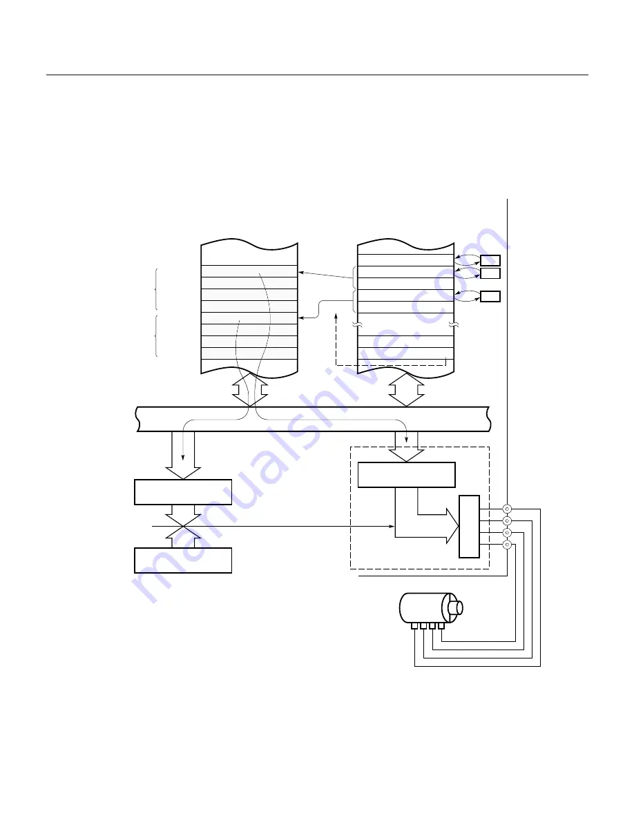
(3) Example of using the type C macro service
The following example shows a pattern output to the real-time output port and how the output interval is
controlled directly.
Update data is transferred from two data areas previously set in the 64K-byte space to the buffer registers
(P0H and P0L) and compare registers (CR10 and CR11) for the real-time output port.
Fig. 12-27 Open-Loop Control for a Stepper Motor by the Real-Time Output Port
0FECFH
MPTH (high)
B0
MPTL (low)
04
MPDH (high)
B0
MPDL (low)
00
MSC
04
Mode register
Channel pointer
E8
CF
(internal RAM)
+1
Type C:
Increment
Internal bus
+1
–1
Output data area
0B007H
T3
T2
T1
D4
D3
D2
D1
T4
64K memory space
0B004H
0B003H
0B000H
Output timing
data area
Macro service control word
Compare register
CR10
8-bit timer/counter 1
TM1
Buffer register
(P0L)
Output latch
Coincidence
Real-time output
trigger/macro
service start
INTC10
Stepper motor
P0
P00
P01
P02
P03
Real-time output port
Summary of Contents for PD78212
Page 11: ......
Page 53: ...24 ...
Page 61: ...32 µPD78214 Sub Series 9 VSS Ground 10 NC non connection Not connected inside the chip ...
Page 65: ...36 ...
Page 83: ...54 ...
Page 135: ...106 ...
Page 271: ...242 ...
Page 405: ...376 ...
Page 417: ...388 ...
Page 423: ...394 ...
Page 449: ...420 ...
Page 457: ...428 ...
Page 471: ...442 ...
Page 487: ...458 ...


